Draper 55075 User manual

DOOR/WINDOW ALARM
STOCK No.55075. PART No.AL5.
02/98
• INSTRUCTIONS •
IMPORTANT: PLEASE READ THESE INSTRUCTIONS CAREFULLY
TO ENSURE THE SAFE AND EFFECTIVE USE OF THIS TOOL.
DRAPER TOOLS LIMITED
Hursley Road, Chandler's Ford,
Eastleigh, Hants. SO53 1YF. England.
Tel: (01703) 266355.
Fax: (01703) 260784.
©Published by Draper Tools Ltd.
No part of this publication may be reproduced,
stored in a retrieval system or transmitted in
any form or by any means, electronic, mechanical
photocopying, recording or otherwise without prior
permission in writing from Draper Tools Ltd.
YOUR DRAPER STOCKIST
INSTRUCTIONS
The unit is equipped with a three position switch, namely: INSTANT ALARM, DELAY
ALARM and OFF.
1. INSTANT ALARM
The alarm will be triggered by the opening of a door, a piercing alarm will be
given immediately.
2. DELAY ALARM
When leaving the premises, switch to this position.
(a) Switch the unit OFF position.
(b) Open the door and switch the unit to DELAY position.
(c) Close the door. The alarm is now automatically activated.
When returning from outside, open the door, there is approximately 8 seconds to
enter the secret code and no alarm will occur. However, if the correct secret code
can not be entered within the delay time, the alarm will sound continuously until
the correct secret code is entered.
3. OFF
Switch to this position, to turn off, to install the unit, replace battery and select
secret code. However, the alarm cannot be terminated by switching to OFF
position once the unit is triggered.
4. PANIC button (red ALARM button)
By pressing this button, the alarm will be triggered immediately. To set the alarm,
enter the secret code.
SECRET CODES SELECTION
(REFER TO FIG.2)
The door/window alarm has a total of 720 secret codes which can be chosen. Each
secret code is combined by three numbers and their sequence is determined by
colour of the lead being connected.Yellow lead represents the first digit, white and
brown leads represent the second and third digits. It is easy to change the secret
code. For example to change secret code to 4, 5, 6, procedures as follows:
(a) Switch the unit to OFF position.
(b) Connect the yellow lead into pin 4, white lead into pin 5 and brown lead into pin 6.
(c) To verify the new secret code, press buttons 4, 5, 6. The LED indicator light will
come on momentarily when the last number (6) is pressed.
NOTE: This unit has been factory coded of 1, 2, 3.
BATTERY REPLACEMENT
1. Switch the unit to OFF position.
2. Remove two screws from the bottom of the unit.
3. Detach the unit from the mounting plate carefully.
4. Connect a fresh 9V battery to the battery snap and insert it into the battery
compartment.
5. Mount the unit back to the mounting plate.
UNIT INSTALLATION
The door/window alarm can be mounted with screws or double-sided adhesive strips
which are provided.
1. To mount with screws, refer to Fig.3.
2. To mount with double sided adhesive strips, refer to Fig.4.
NOTE: (a) Before mounting the alarm with double-sided adhesive strips, clean the
surface of door and frame where the unit and magnet will be located.
Clean also the back of magnet and cover plate.
(b) The arrow on the magnet must point directly at the groove on the side of
the unit.
(c) Proper position of the magnet is imperative. Distance between the magnet
and the unit should be within 1⁄5".
MAINTENANCE
(a) Check the battery every 2 months visually to ensure no leaks have occurred.
A leaking battery will result in poor performance and could damage the alarm.
(b) Do not use the alarm in areas that are exposed to extreme heat or moisture, as this
could adversely affect the performance of the alarm.
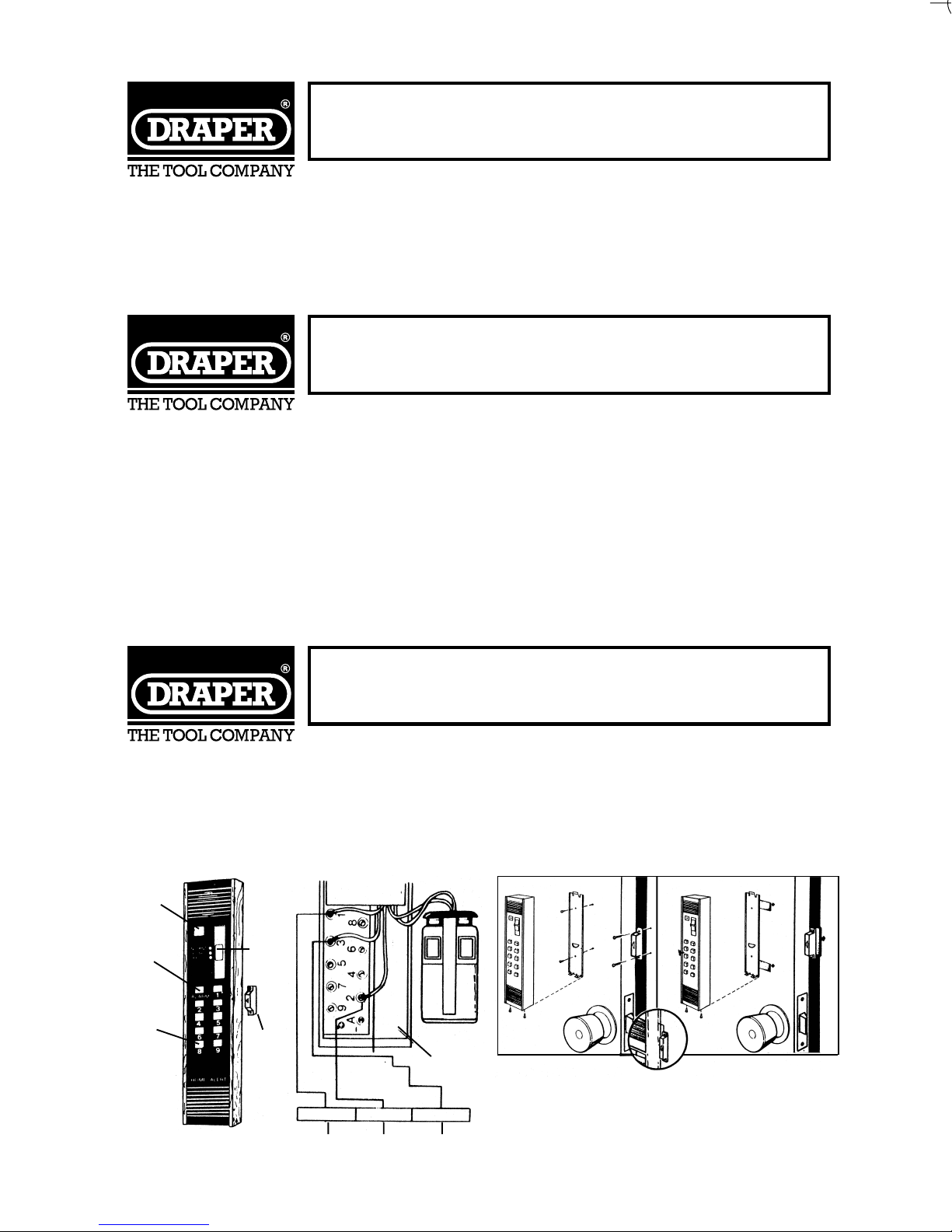
INDICATOR
LIGHT
PANIC
BUTTON
CODE
BUTTONS
FIGURE 1 FIGURE 2 FIGURE 3 FIGURE 4
THREE
POSITION
SWITCH
MAGNET
CODE
SELECTION
WIRES
BATTERY
COMPARTMENTS
YELLOW WHITE BROWN
AB
SECRET CODE
55075 BOOKLET 15/2/02 3:55 PM Page 1

DOOR/WINDOW ALARM
STOCK No.55075. PART No.AL5.
02/98
• INSTRUCTIONS •
IMPORTANT: PLEASE READ THESE INSTRUCTIONS CAREFULLY
TO ENSURE THE SAFE AND EFFECTIVE USE OF THIS TOOL.
DRAPER TOOLS LIMITED
Hursley Road, Chandler's Ford,
Eastleigh, Hants. SO53 1YF. England.
Tel: (01703) 266355.
Fax: (01703) 260784.
©Published by Draper Tools Ltd.
No part of this publication may be reproduced,
stored in a retrieval system or transmitted in
any form or by any means, electronic, mechanical
photocopying, recording or otherwise without prior
permission in writing from Draper Tools Ltd.
YOUR DRAPER STOCKIST
INSTRUCTIONS
The unit is equipped with a three position switch, namely: INSTANT ALARM, DELAY
ALARM and OFF.
1. INSTANT ALARM
The alarm will be triggered by the opening of a door, a piercing alarm will be
given immediately.
2. DELAY ALARM
When leaving the premises, switch to this position.
(a) Switch the unit OFF position.
(b) Open the door and switch the unit to DELAY position.
(c) Close the door. The alarm is now automatically activated.
When returning from outside, open the door, there is approximately 8 seconds to
enter the secret code and no alarm will occur. However, if the correct secret code
can not be entered within the delay time, the alarm will sound continuously until
the correct secret code is entered.
3. OFF
Switch to this position, to turn off, to install the unit, replace battery and select
secret code. However, the alarm cannot be terminated by switching to OFF
position once the unit is triggered.
4. PANIC button (red ALARM button)
By pressing this button, the alarm will be triggered immediately. To set the alarm,
enter the secret code.
SECRET CODES SELECTION
(REFER TO FIG.2)
The door/window alarm has a total of 720 secret codes which can be chosen. Each
secret code is combined by three numbers and their sequence is determined by
colour of the lead being connected.Yellow lead represents the first digit, white and
brown leads represent the second and third digits. It is easy to change the secret
code. For example to change secret code to 4, 5, 6, procedures as follows:
(a) Switch the unit to OFF position.
(b) Connect the yellow lead into pin 4, white lead into pin 5 and brown lead into pin 6.
(c) To verify the new secret code, press buttons 4, 5, 6. The LED indicator light will
come on momentarily when the last number (6) is pressed.
NOTE: This unit has been factory coded of 1, 2, 3.
BATTERY REPLACEMENT
1. Switch the unit to OFF position.
2. Remove two screws from the bottom of the unit.
3. Detach the unit from the mounting plate carefully.
4. Connect a fresh 9V battery to the battery snap and insert it into the battery
compartment.
5. Mount the unit back to the mounting plate.
UNIT INSTALLATION
The door/window alarm can be mounted with screws or double-sided adhesive strips
which are provided.
1. To mount with screws, refer to Fig.3.
2. To mount with double sided adhesive strips, refer to Fig.4.
NOTE: (a) Before mounting the alarm with double-sided adhesive strips, clean the
surface of door and frame where the unit and magnet will be located.
Clean also the back of magnet and cover plate.
(b) The arrow on the magnet must point directly at the groove on the side of
the unit.
(c) Proper position of the magnet is imperative. Distance between the magnet
and the unit should be within 1⁄5".
MAINTENANCE
(a) Check the battery every 2 months visually to ensure no leaks have occurred.
A leaking battery will result in poor performance and could damage the alarm.
(b) Do not use the alarm in areas that are exposed to extreme heat or moisture, as this
could adversely affect the performance of the alarm.
INDICATOR
LIGHT
PANIC
BUTTON
CODE
BUTTONS
FIGURE 1 FIGURE 2 FIGURE 3 FIGURE 4
THREE
POSITION
SWITCH
MAGNET
CODE
SELECTION
WIRES
BATTERY
COMPARTMENTS
YELLOW WHITE BROWN
AB
SECRET CODE
55075 BOOKLET 15/2/02 3:55 PM Page 1
Table of contents
Other Draper Carbon Monoxide Alarm manuals


