Draper FlexShade Tension ZIP Programming manual

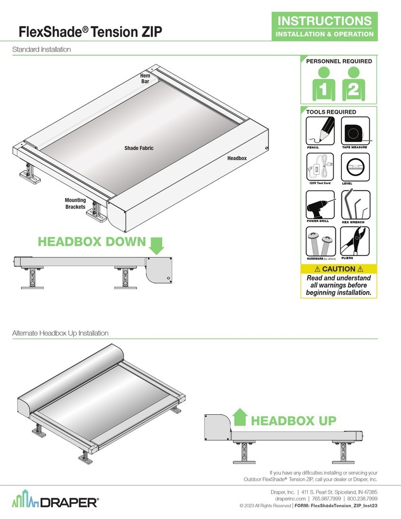
Standard Installation
Alternate Headbox Up Installation
Headbox
Mounting
Brackets
Hem
Bar
Shade Fabric
HEADBOX UP
HEADBOX DOWN
HEADBOX UP
Draper, Inc. | 411 S. Pearl St. Spiceland, IN 47385
draperinc.com | 765.987.7999 | 800.238.7999
© 2022 All Rights Reserved | FORM: OutdoorTension_ZIP_Inst22-R
Outdoor FlexShade® Tension ZIP
INSTRUCTIONS
INSTALLATION & OPERATION
If you have any difficulties installing or servicing your
Outdoor FlexShade® Tension ZIP, call your dealer or Draper, Inc.
21
PERSONNEL REQUIRED
POWER DRILL
PENCIL TAPEMEASURE
(by others)
HARDWARE
LEVEL
HEX WRENCH
120V Test Cord
TOOLS REQUIRED
CAUTION
Read and understand
all warnings before
beginning installation.
PLIERS

Caution:
1.
Inspect all boxes to make sure you have
received the proper shades and parts.
Controls may be shipped separately, or in
same carton as shades.
2.
Open cartons lengthwise, taking care not
to cut into cardboard shipping container.
3.
Before mounting shades, verify
measurements on label provided with shade,
and ensure unit is installed at correct width.
4.
All end caps, fascia, pocket headbox, and
other hardware must be installed level.
Shades must be level and square.
5.
Read the following installation guidelines
thoroughly and follow them carefully.
Failure to do so may cause product to fall or
otherwise fail, and invalidates warranty.
6.
Installer is responsible for selecting mounting
hardware appropriate for site conditions.
Section 1 - Mounting Tension Zip Side Channels
Caution: Before mounting shades, verify measurements on label provided with shade, and ensure unit is installed at correct width.
Section 1.1 - Mounting Considerations
Outdoor Tension ZIP is secured to the building structure by several mounting brackets
(number of brackets is size dependent)
that attach to BOTH Side Channels.
A.
It is recommended shade be mounted with headbox DOWN.
B.
Side rails are universal and can be placed on either side.
C.
Mounting brackets can slide along the entire length side channel
and MUST be secured to the building structure.
D.
Mounting brackets are to be spaced no more than 48"
(1219mm)
apart, and brackets
must be within 6"
(152mm)
of headbox and endcaps.
E.
Channel openings MUST face each other.
F.
Side channels must be parallel, square, in plane, and level with each other.
5/8" Square Nut
(2 per Bracket)
Slides into Side Channel
ADJUSTABLE
BASE BRACKET
4" (100mm) to
6.5" (168mm)
LOOSEN HEX
NUTS to ADJUST
HEIGHT
(2 per Bracket)
4 ½"
(114mm)
2 ½"
(63.5mm)
MAX
HEIGHT
6
5
/
8
"
(168mm)
1 ¾"
(44mm)
PLEASE READ - Field Adjustments
Each Draper Solar Control Shade is tested to
ensure proper operation. Even with this testing,
some field adjustments may be needed for
telescoping.
If the shade is telescoping, place a piece of
shimming fabric into the fabric roll when the shade
is deployed on the side that the fabric will be drawn
toward. For example: if the fabric is tracking to the
left, place the shimming fabric on the right side.
PLEASE READ - Cleaning and Maintenance
Cable and product will settle over first few months and re-adjusting of limits is
required. Failure to do so will result in product possible product damage.
Window covering products manufactured by Draper, when properly installed, should require no operational
maintenance or lubrication.
Most standard Draper fabrics may be cleaned at the window by vacuuming with a soft brush attachment.
They also may be cleaned by using a sponge or soft cloth and mild solution of warm soapy water. A mild
dish-washing liquid is recommended. A clean dry cloth is recommended for the metal finish.
Please Note: Exceptions are GreenScreen Evolve, GreenScreen Revive, Flocké, and Phifer
SW7000 fabrics, which must be cleaned with a dry art sponge.
Section 1.2 - Attaching Brackets to Side Channels
1.
Remove the four
(4)
screws and endcap from each side channel
(fig.1)
.
2.
Slide the
5/8
" Square Nuts
(2 per mounting bracket)
into both side channels
(see fig. 2.)
Note: If using Spreader Bar
(See Section 11)
, you will need to insert the Square Nuts to attach it now.
3.
Attach the mounting brackets
(2 fasteners per bracket)
to the side channels
(see fig. 3)
.
4.
Place side channels in desired position
(See fig. 4)
and mark the location of the bracket mounting slots.
5.
Secure mounting brackets and side channel assembly to building structure
(see fig. 4 DETAIL)
.
Please Note: Installer is responsible for selecting mounting hardware appropriate for site conditions.
WINDOW
OPENING
MOUNTING POINTS
Headbox Width - 2½” (63.5mm)
MOUNTING
BRACKETS
Figure 4
SIDE
CHANNEL
Button-head Screw
5/8" Square Nut
ENGAGED IN
SIDE CHANNEL
5/8" Split Lock Washer
STANDOFF
Mounting Bracket
CABLE
Figure 3
SIDE
CHANNEL
ENDCAP
SCREWS
ENDCAP
x4
Figure 1
SIDE
CHANNEL
5/8” Square Nuts
2 per bracket
Figure 2
Figure 4
DETAIL
page 3 of 20
Outdoor FlexShade® Tension ZIP
page 2 of 20
Outdoor FlexShade® Tension ZIP
WARNING
Improper installation and use of the Outdoor FlexShade Tension Zip can result in serious injury or death. Primarily, injuries can occur if the unit
falls due to imprecise installation, mishandling of the unit during installation, or installation on an insufficient wall or ceiling structure. Please
use extreme care.
1.
Please read the following installation guidelines thoroughly and follow them
carefully. Failure to do so may cause product to fall or otherwise fail, and
could result in serious injury or death.
2.
Installation and calibration of the unit should only be performed by an
authorized, qualified, and experienced professional. In particular, electrical
work and wiring [indicated in diagram by dashed lines] must be completed
only by a qualified professional electrician who has read this manual
completely and is familiar with the construction and operation of this
equipment and the hazards involved.
3.
Do not affix the unit to wall or ceilings that have inadequate strength to
permanently hold the unit during use. It is the owner’s and installer’s
responsibility to confirm the wall or ceiling to which the unit attaches is
sufficient to permanently hold the weight and stress loads of the unit at all
times. Draper®, Inc., is not responsible for improper installation, application,
testing, or workmanship related to the product at place of installation.
4.
It is the installer’s responsibility to make sure appropriate fasteners are used
for mounting.
5.
Never leave the area while operating the unit during installation,
maintenance, or normal operation, unless it is secure and safe.
6.
Before testing or operation, carefully inspect the entire area and path of the
shade and areas underneath the shade to be sure no persons or objects are
in the area.
7.
Turn off power and any nearby equipment or cables carrying electricity
before connecting switches, wires, controls, or electrical components.
8.
Make sure the limit switches are pointed down or accessible when placing
the motor in brackets/end caps.
9.
All motors should be tested and limits set using test cord prior to the final
connection of the shade to building power.
10.
Do not wire motors in parallel without written permission from Draper, Inc.
11.
During testing or operation, carefully watch the surrounding area for any
potential safety concerns including nearby persons or objects.
12.
After installation, the entire system, including all sensors, should be carefully
tested to ensure safe and normal operation. Extreme care should be taken
during testing to remain clear of moving parts to avoid possible injury.
13.
Operation of unit should be performed only by authorized and qualified
personnel, who have been trained in the safe and effective operation of the
unit and understand its safety features.
14.
The safety features of the unit, including sensors, should never be disabled,
bypassed, or overridden. The system should not be operated until all safety
features, including the sensors, are properly and completely installed,
calibrated, and tested.
15.
Unit may need to comply with local, state, or district rules and regulations,
in particular when installed in schools. All applicable rules and regulations
should be reviewed before installation and use.
16.
Failure to precisely follow installation guidelines invalidates all warranties.
17.
Systems is intended for sun shading only. Unit must not be deployed or
operated in any type of precipitation event. Retract the shade to prevent the
accumulation of rain, ice or snow. Product should be installed on a 15 degree
angle to drain water if left deployed. Failure to do so may cause product to
fail, and could result in serious injury or death.
18.
Custom products/installations may not be reflected in this manual. Call
Draper, Inc., if you have questions about the installation of custom products
or any questions about your installation.
Before Beginning Installation
1.
Look for any job site conditions that could interfere with installation or
operation of the system.
2.
Read carefully and be sure to understand all installation instructions and
all related operations manuals. These instructions are intended to serve
as a guide for the installer and owner. They should be followed closely and
combined with the expertise of experienced qualified installers. Draper,
Inc., is not responsible for improper installation, application, testing, or
workmanship related to the product at place of installation. Please retain all
instructions for future use.
3.
Open cartons lengthwise.
4.
Locate and lay out all pieces.
5.
Inspect all boxes to make sure you have received the proper shade and
parts. Controls may be shipped separately, or in same carton as shade.
6.
If you have any difficulties with installing, servicing, or operating your shade,
call your dealer or Draper, Inc., 765-987-7999.
Important Safety Information Important Safety Information
PLEASE READ - Important Installation Information
PLEASE READ - Safety Information
WARNING! - DO NOT DRILL THROUGH OR MODIFY SIDE CHANNELS DURING INSTALLATION.
Modification of Side Channels could cause product to be damaged or otherwise fail.
Please Note: Installer is responsible
for selecting mounting hardware
appropriate for site conditions.

Section 2 - Mounting Headbox to Side Channels
Section 2.1 - Attaching Headbox and Fabric Assembly to Side Channels
1.
Remove the Headbox Cover screws
(one per side)
and then carefully remove the Headbox Cover
(see fig. 4)
.
2.
Remove the four
(4)
screws from side channel attachment tangs
W
(2 per tang)
on each side of the headbox.
3.
Connect the unit to building power using a test cord.
Deploy the shade approximately 15"
(38cm)
.
4.
Insert the Hem Bar into the side-channels.
5.
Slide the tangs on each end of headbox into the side-channels.
6.
With the zipper secured in the retainer strip, slide the hem bar,
fabric assembly and headbox into place.
ZIP HEM BAR
HEADBOX COVER
1A
ZIP HEM BAR
HEADBOX COVER
1B
Figure 4
Insert Headbox
into Side Channel
Fabric Channel
BACK of HEADBOX
SIDE CHANNEL
Fabric Bundle
Fabric
Panel
REVERSE
VIEW
Side Channel
Hem
Bar
Fabric
Headbox
4
Side Channel
Headbox
Hem
Bar
5
Headbox
Hem
Bar
Side Channel
6
The tabs on each endcap will slide
into RECEIVER SLOT the side
channel.
Tab Inside
Side Channel
HEADBOX
7.
Pull the retainer strip out approximately 3"
(76mm)
.
8.
Temporarily press the fabric out of the side channel near the headbox and re-install the screw removed in step 1.
9.
Push retainer strip back into side channels. Leave the end caps unattached for now.
8
2
SIDE CHANNEL
ATTACHMENT TANG
REMOVE
SCREWS
page 5 of 20
Outdoor FlexShade® Tension ZIP
page 4 of 20
Outdoor FlexShade® Tension ZIP
3
Side Channel
Hem
Bar
Fabric
Headbox
120V Test Cord
HEX WRENCH
4mm
SIDE
CHANNEL
PULL OUT
RETAINER
STRIP
3"
(76mm)
7
PLIERS

FABRIC
ROLL
FABRIC
ROLL
Fabric From Bottom of Roller
THROUGH HOLE
IN SPOOL
FABRIC from
Bottom of Roller
CABLE FROM
PULLEY A
THROUGH HOLE
IN SPOOL
SIDE VIEW
SIDE VIEW
Cable Over Top of Roller and
Around Motor Spool
At Least 3 Wraps
M
O
T
O
R
S
P
O
O
L
M
O
T
O
R
S
P
O
O
L
FABRIC
ROLL
Please Note: 2-3 wraps of cable should always remain on the spool.
Figure 5C
DETAIL
BACK of HEADBOX
Fabric Bundle
A
From
Under
Pulley
REVERSE
VIEW
SIDE CHANNEL
B
To Pulley Wrap Cable
over and
around spool
on motor
1
Figure 5A
DETAIL
SHADE FABRIC
1 - 2 - 3
A
1. From
Under
Pulley
2. Wrap Cable
over and around
spool on motor
AT LEAST 3 WRAPS
3. Through Hole in Spool
4. Tie with
Double
Square
Knot
5. Pull the other
end of cable
to remove slack.
5. Pull the other
end of cable
to remove slack.
Figure 5B
DETAIL Cable MUST wrap
in the OPPOSITE
DIRECTION of
Shade Material
Section 2.2 - Attaching Cables to Motor Spools
1.
Feed the cable from under Pulley A
(on end of side channel)
and wrap cable over and around the cable spool AT LEAST 3 WRAPS on each end of the
fabric assembly. If cable is routed OVER pulley, re-route under in accordance with Fig 5 below.
Section 2.3 - Re-attaching Side Channel Endcaps
1.
Thread cable around PULLEY B located within each side channel end cap.
2.
Re-install the endcaps to side channels.
Figure 8
PULLEY B
PULLEY B
CABLE
from Side Channel
END CAP CABLE ROUTING DETAIL
Figure 8
DETAIL A
1
Replace the four (4)
screws and Side
Channel Endcap
Figure 8
DETAIL B
2
Section 3 - Routing Cables
Section 3.1 - Removing Hem Bar Cover
1.
Separate the snap-on Hem Bar Cover from the Hem Bar
(See Fig. 9)
. This will expose the location where
the pulleys and tie-off cleats that will be used to set the cable tension.
WARNING: Hem bar cover is attached to the hem bar by two
(2)
safety tethers.
In some instances, these safety tethers may need to be removed to aid in cable routing.
SAFETY TETHERS MUST BE REATTACHED PRIOR TO HEM BAR COVER BEING REATTACHED.
PRODUCT IS NOT PROPERLY INSTALLED IF SAFETY FEATURES HAVE BEEN DISABLED.
Attach Spring to Hem Bar
Section 3.2 - Installing Tensioning Springs within Hem Bar
1.
Locate both tensioning springs and pulleys
(packed with shade)
.
2.
Attach one pulley to one end of each spring, and attach the other end to provided hooks within Hem Bar
(See Fig. 10)
.
3.
Route cable from PULLEY B at the end of the side channel, the cable will then go on the outside
of the side rail to PULLEY C on the hem bar
(See Fig. 11 on next page)
.
TENSIONING SPRING
Figure 10
Figure 9
page 7 of 20
Outdoor FlexShade® Tension ZIP
page 6 of 20
Outdoor FlexShade® Tension ZIP

CABLE ROUTING DETAIL A Figure 11
DETAIL A
TIE END OF CABLE INTO A LOOP
and PULL UNTIL SPRING
EXTENDS AT LEAST 1” (25mm)
and ATTACH TO CLEAT
HEM BAR
(Cover Removed)
ED
CDEC
F
F
TIE END OF CABLE INTO A LOOP
and PULL UNTIL SPRING
EXTENDS AT LEAST 1” (25mm)
and ATTACH TO CLEAT
From RIGHT
Side Channel Pulley
From LEFT
Side Channel Pulley
FABRIC PANEL
(Engaged in Zippers)
Roller Assembly
B
A
B
A
Figure 11
Section 3.3 - Routing Cables within Hem Bar -
For smaller sizes up to 84"
(213cm)
Wide - Cable Routing A
1.
Refer to CABLE ROUTING DETAIL A below
(Fig. 12 Detail A)
.
2.
Route cables from PULLEY C to PULLEY D to PULLEY E and then to CLEAT F.
PLEASE NOTE: Tying a loop in the end of the cable will aid in pulling the cable taught.
Be sure cable is properly engaged in ALL pulleys prior to operating shade.
Improper cable routing can cause product to be damaged or otherwise fail.
PLEASE NOTE: Do not put the cover on at this time.
TIE END OF CABLE INTO A LOOP
and PULL UNTIL SPRING
EXTENDS AT LEAST 1” (25mm)
and ATTACH TO CLEAT
HEM BAR
(Cover Removed)
ED
CDEC
F
F
TIE END OF CABLE INTO A LOOP
and PULL UNTIL SPRING
EXTENDS AT LEAST 1” (25mm)
and ATTACH TO CLEAT
From RIGHT
Side Channel Pulley
From LEFT
Side Channel Pulley
FABRIC PANEL
(Engaged in Zippers)
Roller Assembly
B
A
B
A
WIDTH
LENGTH
40" 48" 60" 72"
102cm 123cm 153cm 183cm
12" 30cm
24" 61cm
36" 91cm
48" 122cm
60" 152cm
72" 183cm
84" 213cm
96" 244cm
108" 274cm
120" 305cm
132" 335cm 50"
144" 366cm 50"
156" 396cm 50"
168" 427cm 50"
CABLE
ROUTING A
SMALL 17" SPRING
CABLE
ROUTING A
LARGE 21" SPRING
page 9 of 20
Outdoor FlexShade® Tension ZIP
page 8 of 20
Outdoor FlexShade® Tension ZIP

Section 3.4 - Routing Cables within Hem Bar - For larger sizes wider than 84"
(213cm)
1.
Refer to CABLE ROUTING DETAIL B below
(Fig. 12 Detail)
.
2.
Route cables from PULLEY C to PULLEY D to PULLEY E to PULLEY F to
PULLEY G and then to CLEAT H.
PLEASE NOTE: Tying a loop in the end of the cable will aid in pulling the cable taught.
Be sure cable is properly engaged in ALL pulleys prior to operating shade.
Improper cable routing can cause product to be damaged or otherwise fail.
PLEASE NOTE: Do not put the cover on at this time.
HEM BAR
(Cover Removed)
HEM BAR
(Cover Removed)
FABRIC PANEL
(Engaged in Zippers)
Roller Assembly
Center
Line
Tensioning SpringTensioning Spring
Tensioning Spring
Tensioning Spring
D
F
H
E
G
C
TIE END OF CABLE INTO A LOOP
and PULL CABLE UNTIL SPRING
EXTENDS AT LEAST 1” (25mm)
and ATTACH TO CLEAT at “
H
”
B
GF
ED
C
B
LEFT SIDE CLEAT
H
From LEFT
Side Channel Pulley
LEFT SIDE CABLE ROUTING DETAIL B
Figure 12
DETAIL
HEM BAR
(Cover Removed) HEM BAR
(Cover Removed)
FABRIC PANEL
(Engaged in Zippers)
Roller Assembly
Center
Line
Tensioning SpringTensioning Spring
Tensioning Spring
Tensioning Spring
D
F
H
E
G
C
TIE END OF CABLE INTO A LOOP
and PULL CABLE UNTIL SPRING
EXTENDS AT LEAST 1” (25mm)
and ATTACH TO CLEAT at “
H
”
B
GF
ED
C
B
LEFT SIDE CLEAT
H
From LEFT
Side Channel Pulley
From RIGHT
Side Channel Pulley
G
F
D
B
H
TIE END OF CABLE INTO A LOOP
and PULL CABLE UNTIL SPRING
EXTENDS AT LEAST 1” (25mm)
and ATTACH TO CLEAT at “
H
”
C
E
RIGHT SIDE CLEAT
HEM BAR
(Cover Removed)
HEM BAR
(Cover Removed)
FABRIC PANEL
(Engaged in Zippers)
Roller Assembly
Center
Line
Tensioning SpringTensioning Spring
Tensioning Spring
Tensioning Spring
From RIGHT
Side Channel Pulley
G
F
D
B
H
TIE END OF CABLE INTO A LOOP
and PULL CABLE UNTIL SPRING
EXTENDS AT LEAST 1” (25mm)
and ATTACH TO CLEAT at “
H
”
C
E
RIGHT SIDE CLEAT
RIGHT SIDE CABLE ROUTING DETAIL B
Figure 12
WIDTH
LENGTH
84" 96" 108" 120" 132" 144" 156" 168" 180" 192"
213cm 244cm 2 74 cm 305cm 335cm 366cm 396cm 427cm 4 57cm 488cm
12"
30cm
24"
61cm
36"
91cm
48"
122cm
60"
152cm
72"
183cm
84"
213cm
96"
244cm
108"
274cm
120"
305cm
132"
335cm
144"
366cm
156"
396cm
168"
427cm
180"
457cm
192"
488cm
204"
518cm
216"
549cm
228"
579cm
240"
610cm
CABLE
ROUTING B
LARGE 21" SPRING
page 11 of 20
Outdoor FlexShade® Tension ZIP
page 10 of 20
Outdoor FlexShade® Tension ZIP

Minimum Tension with Hem Bar in Center
When springs sag, stop motor and remove slack in cable.
Section 4 - Removing Excess Slack from Tensioning Cables
Section 4.1 - Deploying shade to remove excess slack in cables:
All steps in Sections 3.4 and 3.5 are to be done uniformly to BOTH CABLES and BOTH TENSIONING SPRINGS.
1.
Once tensioning springs are installed and attached to cables, use a test cord to deploy shade.
Refer to Figure 13 below.
2.
Observe shade as it travels. Ensure that both sides of the hem bar are traveling at the same speed
and that movement is uniform.
As shade deploys, cables will go slack and the tensioning springs will sag
(see Fig. 15 on page 11)
.
STOP MOTOR IMMEDIATELY if hem bar becomes misaligned, stuck or stops traveling uniformly.
3.
With motor stopped, remove slack in fabric by moving hem bar evenly by hand through side
channels. Ensure the hem bar is properly aligned within the side channels.
4.
Remove cable slack
(See Fig. 14)
.
A.
Remove cable loop from cleat and tie new knot in cable.
B.
Pull cable loop until spring extends and reattach to cleat.
TIP: Tying a new loop in the cable closer to the cleat will allow for better leverage and will
require less stopping to remove slack.
6.
Continue deploying the shade, stopping motor IMMEDIATELY if hem bar becomes misaligned,
stuck or stops traveling uniformly. Removing cable slack in accordance with step 4.
7.
Stop when the shade is 90% deployed.
Pull cable, adding tension until spring extends 1"
(25mm)
and reattach each cable to its cleat.
Use guide below to for proper spring lengths to be achieved in Step 7 above.
Measure the length of BOTH tensioning springs to ensure they are of equal length and under equal tension.
Size of springs provided is determined by size of shade.
Both springs provided with each shade will be identical in length.
MAX. Spring Deflection: 23 ½"
(597mm)
RELAXED SPRING: 17"
(432mm)
MAX. Length when Extended: 32"
(813mm)
RELAXED SPRING: 21"
(533mm)
Maximum Spring Deflection for spring sizes:
Springs size is configured based on the size of the shade ordered. Springs provided with configured shade will be identical.
Measure springs relaxed with zero tension, then compare their length while extended under tension.
DO NOT STRETCH or EXTENDED SPRINGS BEYOND MAX LENGTHS SHOWN BELOW (Fig. 16).
WARNING:
DO NOT STRETCH OR
EXTENDED SPRINGS
BEYOND MAX LENGTH
Section 4.2 - Retract shade to remove remaining excess slack
(adding tension)
in cabled system:
The Outdoor tensioned Zip will need to be retracted and deployed several times to remove all slack from cables.
The cables in the system will settle over time.
All steps in Sections 3.4 and 3.5 are to be done uniformly to BOTH CABLES and BOTH TENSIONING SPRINGS.
1.
Retract the shade. Observe to ensure that both sides of the hem bar are still moving uniformly through side channels.
2. STOP MOTOR IMMEDIATELY if hem bar becomes misaligned, stuck or stops traveling uniformly.
Please note: While retracting, system will lose tension as hem bar approaches the center of the shade
(50% retracted)
,
and will begin adding tension as the hem bar approaches the head box
(100% retracted)
.
3.
Measure the length of tensioning springs to ensure they are equally stretched and not hyper-extended.
Refer to max spring deflection chart BELOW.
4.
If more tension is required, deploy shade to 90%. Add tension by pulling cables until taut and reattaching each to its C L E AT.
5.
Repeat sections 3.4 and 3.5 until shade operates smoothly.
6.
Set motor limits
(see Section 5)
.
PLEASE NOTE: Cable and product will settle over first few months and re-adjusting of limits is required.
Failure to do so will result in product possible product damage.
IF SPRINGS ARE HYPER EXTENDED:
1. Move shade to 50% deployed
(Minimum system tension)
.
2. Carefully, unhook the cable at the Cleat
and reattach it with less tension.
3. Repeat with the other cable.
Minimum Cable Tension with Hem Bar in Center
Maximum Cable Tension When Retracted
Attach Cables to Springs Here and Adjust As Shade Deploys
Increased Cable Tension When Deployed
Roller Assembly
Figure 13
Please note:
System will lose
tension as hem bar
approaches the
center of shade.
PULL CABLE LOOP until spring
extends and reattach to Cleat
B
KNOT TIED IN CABLE TO PREVENT SLIPPAGE
Remove Cable Loop from Cleat
and tie a new knot in the CABLE
A
Figure 14
Figure 15
Length when Extended: 18"
(457mm)
RELAXED SPRING: 17"
(432mm)
SMALL SPRING - CABLE ROUTING A
Length when Extended: 22"
(559mm)
RELAXED SPRING: 21"
(533mm)
LARGE SPRING - CABLE ROUTING A or B
Figure 16
page 13 of 20
Outdoor FlexShade® Tension ZIP
page 12 of 20
Outdoor FlexShade® Tension ZIP
120V Test Cord

Section 5 - RF Remote Programming Instructions
Please Note: The motor ships with no programming. Follow these instructions to program unit to the desired transmitter.
Setting an Intermediate Stop -
Shade MUST BE in USER mode.
1.
Move shade to desired mid-point
location and hold MY/STOP button
until motor jogs.
2.
To test, press the MY/STOP button
when motor is standing still. The shade
will move to that intermediate location.
3.
To delete an intermediate stop, go to the
intermediate stop and hold the MY/STOP
button until motor jogs.
Add a Channel -
Shade MUST BE in USER mode.
1.
Select channel currently operating
motor, then hold programming button
until motor jogs.
2.
Select new channel to add to motor, then
hold programming button until motor jogs.
3.
The motor should now work on both the
old and new channel.
Delete a Channel -
Shade MUST BE in USER mode.
1.
Select channel operating motor desired,
then hold programming button until
motor jogs.
2.
Select channel to remove, then hold
programming button until motor jogs.
Motor should now only work
on channel kept from Step 1.
1.
Select a transmitter channel to assign motor.
Hold UP and DOWN buttons
until motor jogs, then release.
2.
Check motor direction. To reverse motor
direction, hold MY/STOP button for
5 seconds until motor jogs. Check direction
again.
3.
Move motor to upper limit position. Hold MY/
STOP and DOWN buttons until motor moves
down, then release. Use UP and DOWN buttons
to move shade to correct lower limit and press
M Y/ S TO P.
4.
While motor is at lower limit, hold UP and MY/
STOP buttons until motor moves up, then
release. The shade should move to upper limit
and stop.
5.
Next, hold MY/STOP button until motor jogs.
6.
Put motor into USER MODE by holding small
programming button on the back of transmitter
and waiting for motor to jog.
Adjust Limits in User Mode
1.
Move motor to limit
(upper or lower)
to be
changed. Shade must move to previously
set limit and will stop automatically.
2.
Hold UP and DOWN buttons until motor
jogs.
3.
Move motor to its new limit location and
hold MY/STOP button until motor jogs.
Reset Motor
1.
Disconnect for 3 seconds, reconnect for
10 seconds, disconnect for 3 seconds.
Shade will roll.
2.
Hold program button on remote and wait
for 2 separate jogs.
Motor is now reset.
Channel
Selector
UP
STOP
DOWN
LED Lights
SHADE
SHADE
SHADE
BACK
Programming
Button
Pen
BACK
Programming
Button
Pen
BACK
Programming
Button
Pen
BACK
Programming
Button
Pen
SHADE
SHADE
upper
or
lower
limit
Section 6 - Limit Switch Adjustments
Standard and Quiet Motors
Caution: Unit ships without limits. Limits will need to be set
before the unit is operated. Always be prepared to shut off
manually when new adjustment is being tested.
Push Button Limits
1.
Fully depress both limit switch push buttons, then operate
wall switch to make sure system works properly.
2.
Raise shade to desired "UP" stop position.
3.
Set upper limit by depressing proper
(back)
push button.
4.
Lower shade to desired "DOWN" stop position.
5.
Set lower limit by depressing proper
(front)
push button.
Screw-Type Limits
6.
Determine which direction of fabric travel corresponds with
arrows on motor.
Caution:
- Be sure all switches are in
"off" position before adjusting
limit switches.
- Shade may be damaged by
running shade fabric up too
far and exposing roller.
- If using a group control
system, each limit switch
must be set prior to
connecting to system.
- Motor must be installed so
limit switches are pointed up
or accessible.
7.
Operate shade to desired "down" stop position.
Set limit by turning proper socket toward "+" to lower limit, and "-" to raise it.
8.
Operate shade to desired "up" stopping position.
Set limit by turning proper screw toward "-" to raise limit, and "+" to lower it.
Please Note: Each full rotation of the limit screw equals approximately
5/8
"
(16mm)
of shade travel, which may require rotating the limit screw several times.
Caution: DO NOT allow the hem bar to hit the upper roller or fascia. This will damage the unit.
Screws
+
+
Front
Back
Bottom View
Side View
GLASS SIDE
ROOM SIDE
GLASS SIDE
ROOM SIDE
Front
Back
Bottom View
Side View
GLASS SIDE
ROOM SIDE
Front
Back
Bottom View
Side View
PUSH BUTTON LIMITS Standard right-hand
motor configuration shown
Screws
+
+
Front
Back
Bottom View
Side View
GLASS SIDE
ROOM SIDE
Screws
+
+
Front
Back
Bottom View
Side View
GLASS SIDE
ROOM SIDE
SCREW-TYPE LIMITS Standard right-hand
motor configuration shown
Section 7 - Complete Electrical Connection
Operates on 110-120V, 60 Hz. current. Shade is shipped with internal wiring complete and control switch
(es)
fully boxed, and supplied with a 6'
(183 cm)
cable
lead
(standard)
. Longer lead can be substituted by removing two screws in motor end of roller, removing lead, plugging new lead in, and replacing screws. Wire to
connect shade to switch
(es)
and switch
(es)
to power supply should be furnished by installer. Connections should be made in accordance with attached wiring
diagram, and wiring should comply with national and local electrical codes.
DO NOT wire motors in parallel without written permission from Draper.
All operating switches should be “off” before power is connected.
Controls & System Overview
Sonesse®RTS 120VAC Motors
B WG
RTS
MOTOR
120V
110-120V Line
Decora RTS
Wireless Keypad
Patio
RF Remote
STOP
Dashed Wiring
by Electrician
NOTE: Test shade operation
If shade direction does not
correspond with the switch
orientation, turn power back
off and switch the red and black
wires from the motor to the switch.
Do not wire motors in parallel without
written permission from Draper.
Controls & System Overview
Sonesse®120VAC Motors
WB RG
B
Control
Switch
Single Gang
Box (by others)
120V
MOTOR
110-120V Line
Dashed Wiring
by Electrician
Sonesse®is a registered trademark of Somfy®Systems, Inc.
Please Note: NEMA 3 prong
plugs provided by others.
page 15 of 20
Outdoor FlexShade® Tension ZIP
page 14 of 20
Outdoor FlexShade® Tension ZIP

Section 10 - Mounting Bracket Dimensions
5/8" Square Nut
(2 per Bracket)
Slides into Side Channel
ADJUSTABLE
BASE BRACKET
4" (100mm) to
6.5" (168mm)
LOOSEN HEX
NUTS to ADJUST
HEIGHT
(2 per Bracket)
4 ½"
(114mm)
2 ½"
(63.5mm)
MAX
HEIGHT
6
5
/
8
"
(168mm)
1 ¾"
(44mm)
5"
(127mm)
1"
(25mm)
13
/
16
"
(21mm)
11
/
16
"
(17mm)
1
1
/
2
"
(38mm)
2
7
/
8
"
(73mm)
2
7
/
8
"
(73mm)
3
7
/
8
"
(95mm)
Square Nut
(2 per Bracket)
Slides into Side Channel
MOUNTING
BRACKET
Side
View
To p V iew
Section 9 - Assembled Dimensions
"
(6.35mm)
5"
(133mm)
5"
(133mm)
5"
(133mm)
Hem Bar Thickness: 2"
(51mm)
1"
(44mm)
2"
(73mm)
1"
(44mm)
1"
(32mm)
Shade Width
Shade
Height
Side
Channel
Length
Hem Bar Width
4"
(102mm)
Fabric Width
ELEVATION
VIEW
SIDE
VIEW TOP
VIEW
Hem Bar
Thickness:
2"
(51mm)
1 ¼" (32mm)
Edge of Shade
to Mounting Point
Mounting Bracket
Channel
Mounting Bracket
Channel
MOUNTING POINTS:
Headbox Width - 2 ½” (63.5mm)
Section 8 - Cable Exit
The Outdoor FlexShade®Tension ZIP can be ordered with a cable exit pre-drilled in the side or back of the Headbox
(See Fig. 17)
.
If no cable exit is specified, the cable is routed down and out the fabric opening under the motor.
Please Note: Right hand motor is shown.
TOP
(19mm)
(17m m)
Cable Exit:
SIDE
BACK
(13mm)
SIDE
(Endcap)
Figure 17
(9.5mm)
(13mm)
1
(30mm)
Cable Exit:
BACK
BACK
(13mm)
TOP
SIDE
(Endcap)
Figure 19
page 17 of 20
Outdoor FlexShade® Tension ZIP
page 16 of 20
Outdoor FlexShade® Tension ZIP

Section 11 - Side Channel Spreader Bar
Section 11.1 - Spreader Bar Dimensions
Section 11.2 - Spreader Bar Installation
The Side Channel Spreader Bar is to be used when shade fabric
tension distorts the side channels, interfering with the operation
of the shade
(see Figure 15)
.
6"
(152mm)
2 7/16"
(62mm)
Shade Width -
7
/8"
(22mm)
3"
(76mm)
3/8" Square Nut
(2 per Bracket) Slides into Side Channel
SPREADER BARSPREADER BAR
Side
View
SIDE CHANNEL
SPREADER BAR
C126.392SA
Button-head Screw
5/8” Square Nut
ENGAGED IN
SIDE CHANNEL
Washer
Split Lock Washer
Spreader Bar
Figure 15
page 19 of 20
Outdoor FlexShade® Tension ZIP
page 18 of 20
Outdoor FlexShade® Tension ZIP

page 20 of 20
Outdoor FlexShade® Tension ZIP
Other manuals for FlexShade Tension ZIP
1
Table of contents
Other Draper Outdoor Furnishing manuals
Popular Outdoor Furnishing manuals by other brands
Safavieh
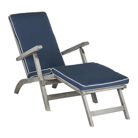
Safavieh PAT7015 Aassembly Instructions

Sojag
Sojag SUNSHELTER Assembly manual
Rutland County Garden Furniture
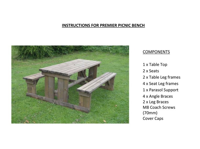
Rutland County Garden Furniture PREMIER instructions
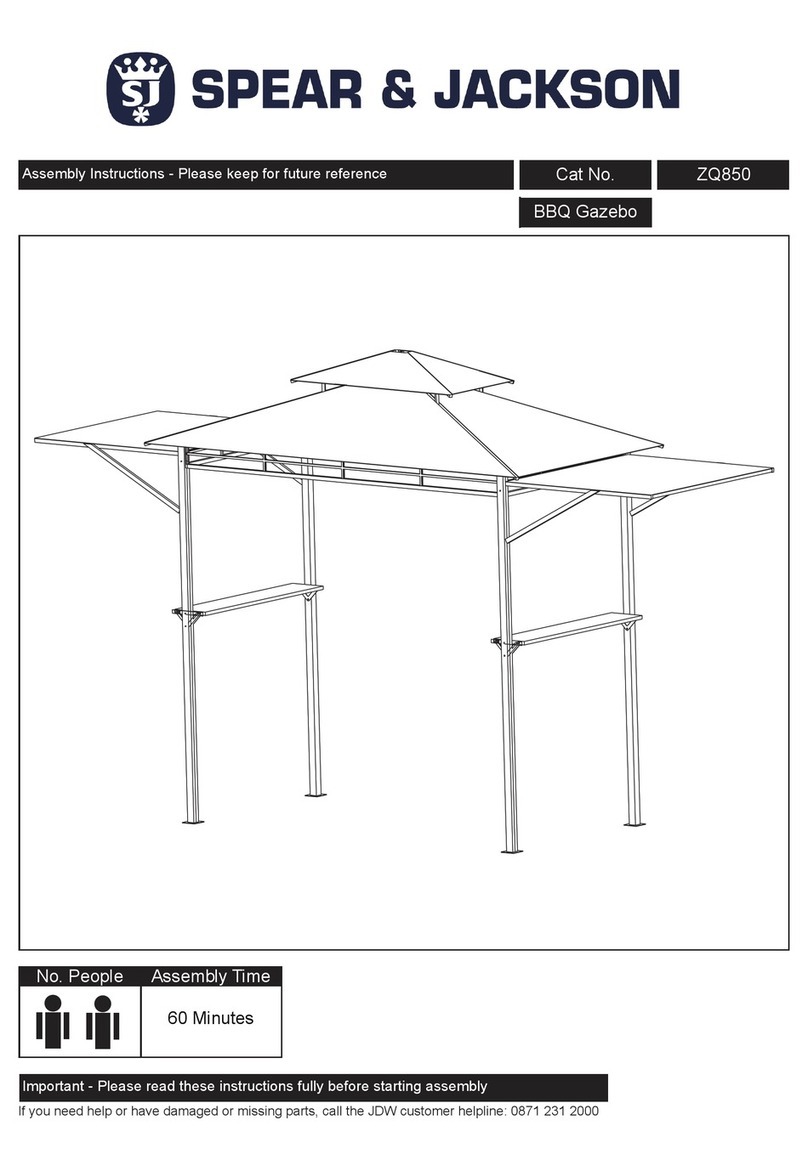
Spear & Jackson
Spear & Jackson ZQ850 Assembly instructions
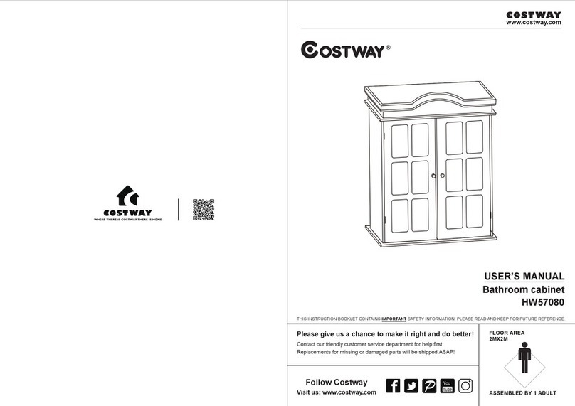
Costway
Costway HW57080 user manual
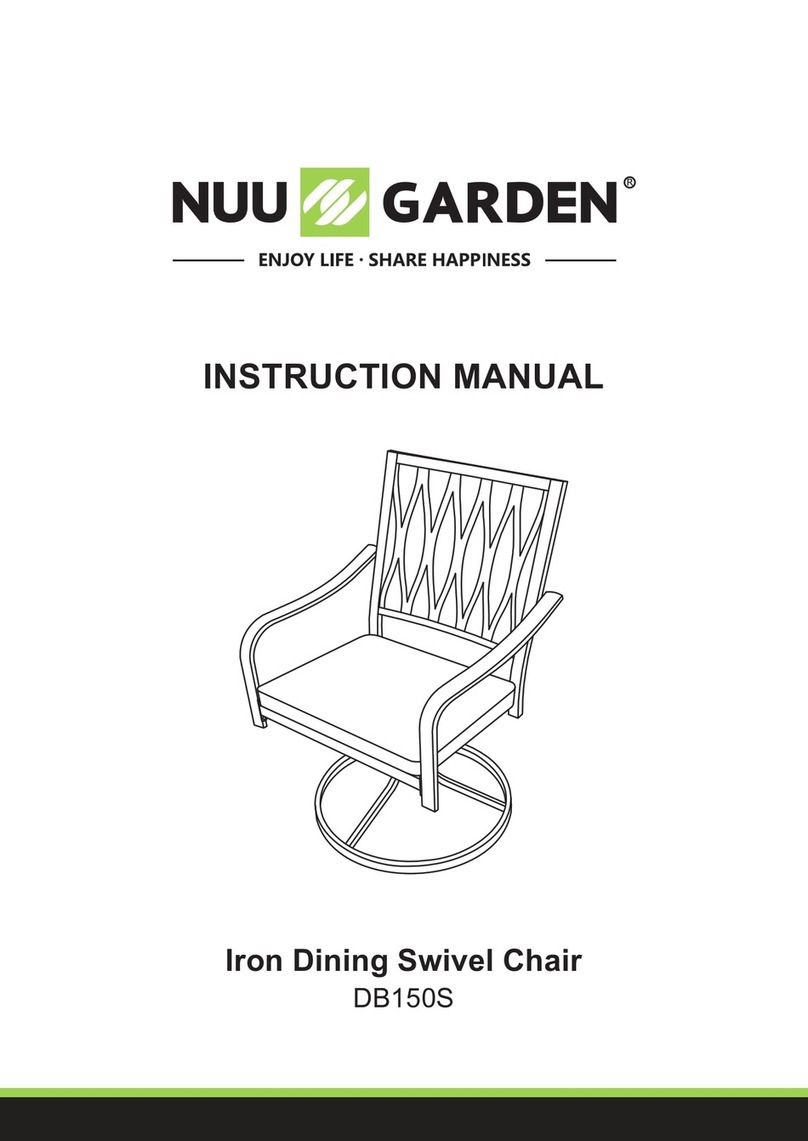
Nuu Garden
Nuu Garden DB150S instruction manual
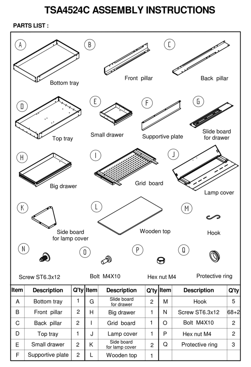
TOPMAQ
TOPMAQ TSA4524C Assembly instructions
SUNS
SUNS Alvaro A Assembly instruction

Dunster House
Dunster House Atlas installation manual

Yardistry
Yardistry MERIDIAN YM11756 Installation and operating instructions

Royal garden
Royal garden GRLGZBGRY Assembly instructions
Weishaupl
Weishaupl Cross Assembly instructions
