4
(orbeforetheactivespeakers),withtheamplifiervolume
settomaximum.Ifthe SP2120weretobeconnectedearlier
inthechain,priortothe pre-amp/mixer for example, then
itwouldbepossibleto addgain,sendingnoiselevelshigher
thanrequired.
TheSP2120 can be usedinaconfiguration where a stereo
outputisdistributed around several speakers. Fig.3shows
a setup where the signal is distributed into six pairs using
a Drawmer DA6, whilst still providing speaker protection
for all twelve speakers. Again, note the position of the
SP2120’s along the audio chain - they should all be
connected directly before the amplifier that is supplying
thespeakers(oractivespeakers), withtheamplifiervolume
set to maximum.
INSTALLATION
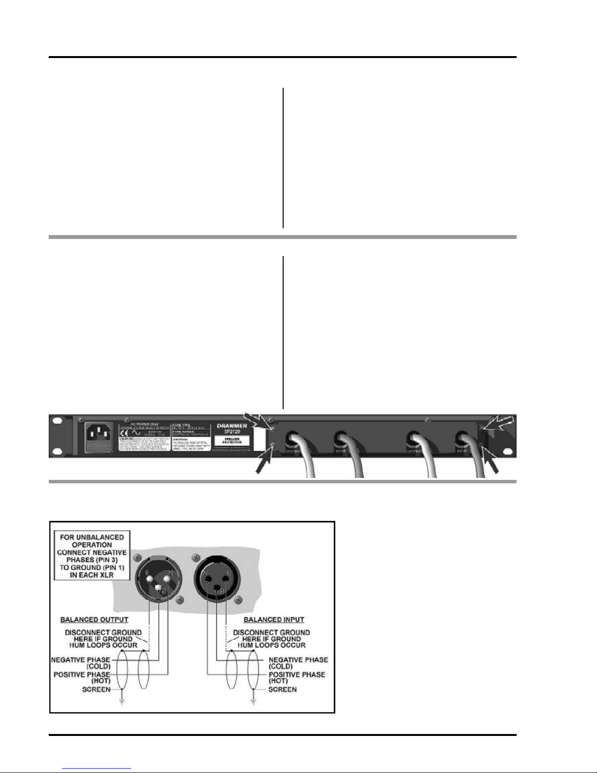
AUDIO CONNECTIONS
The inputs and outputs are electronically balanced XLRs where pin 1 is screen, pin 2 hot, pin 3 cold and the XLR shell
• Interference:
If the unit is to be used where it maybe
exposedto highlevels ofdisturbance such
asfoundclosetoaTV orradio transmitter,
we advise that the unit is operated in a
balancedconfiguration. The screensofthe
signal cables should be connected to the
chassisconnectionon the XLR connector
as opposed to connecting to pin1. The
SP2120 conforms to the EMC standards.
• Ground Loops:
Ifgroundloop problems are encountered,
never disconnect the mains earth, but
instead, try disconnecting the signal
screen on one end of each of the cables
connecting the outputs of the SP2120 to
the patchbay. If such measures are
necessary, balanced operation is
recommended.
fig.1 XLR WIRING
The SP2120 Speaker Protector is designed for standard
19"rack mounting and occupies 1U of rack space.Where
possible, avoid mounting the unit directly above power
amplifiersorpowersuppliesthat radiatesignificantamounts
ofheat.
If the unit is to be used in a mobile situation, it is strongly
recommended that the rear of the unit is supported in the
carryingracktoavoidbendingthefrontpanelrackmounting
‘ears’.Usefibreorplastic washerstopreventthefrontpanel
becomingmarkedbythemountingbolts.Alwaysconnect
the mains earth to the unit.
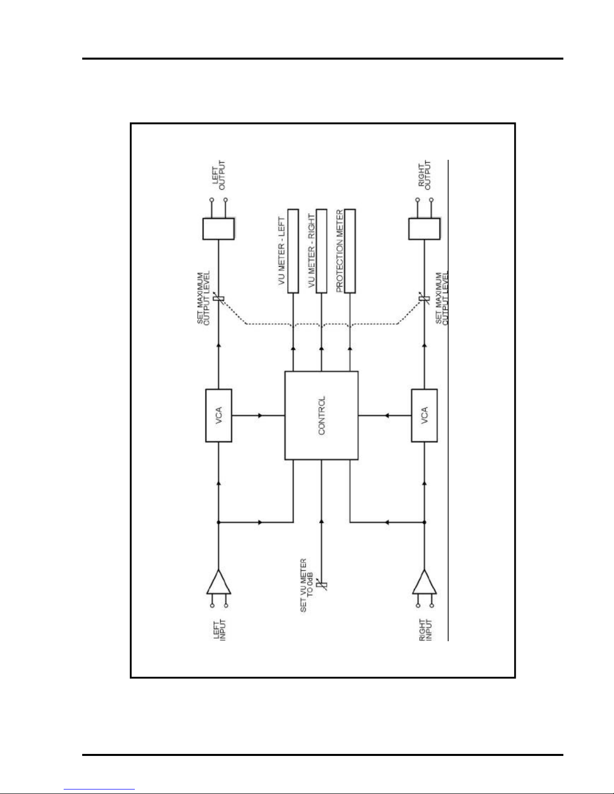
Fig. 2 shows the ideal connection setup, providing the
greatest protection for your system. Note the position of
theSP2120 along theaudiochain - itshouldbe connected
directlybeforetheamplifierthatissupplyingthespeakers,
Drawmerhavegoneto great lengths to make the Speaker
Protector tamper-proof by incorporating the locking
mechanism on the front. However, if the rear of the unit,
alongwiththe power amplifier, were reconnected then the
protectionsystemwouldeffectivelybebypassed.Forthis
reason Drawmer have designed the Speaker Protector
Tamper-proof Bracket - trapping the XLR’s in place and
making it extremely difficult to disconnect them without
removing the bracket. This bracket could be specified in
order to conform to Local Authority noise abatement
regulations.
Installation of the Tamper-proof bracket could not be
simpler: After setting up the SP2120 Speaker Protector
as described in the manual, with the XLR’s in place,
simplyslidetheTamper-proof Bracketoverthe rear of the
unit,making sure that theprotrudingcableslocate through
is connected to chassis. The operating
levelis nominally+4dBu.Balanced use is
recommended.
the gaps on the bracket. Next, screw in to place at the
four locating points (arrowed below) using the M3 screws
provided. Further protection can be gained by fitting M3
TORXtamperproof screws, toamaximum lengthof6mm,
though a specialist screwdriver will also be required.
In addition, for extra protection, both the SP2120 and the
power amp should be locked in a rack, where access to
therear is very difficult.
You should note that the Tamper-proof bracket is only
availableforSP2120’swho’sserialnumberis0845or higher
(September 2006). On older versions the bracket could
be retro- fitted, though this would invalidate any warranty
thatDrawmerhas provided for the SP2120.Alternatively,
Drawmercould bring your SP2120 up to current Drawmer
specification-pleasecontactyour localdistributororemail:
TAMPER-PROOF BRACKET