Dream-Flight Libelle User manual


Discus Launch for Everyone!
There are few experiences in model aviation more satisfying to the soul than flying an efficient, slow-moving
glider that has been launched to soaring altitude by hand. The Libelle takes RC hand-launch glider flying to the
next level, building off of the global acceptance of the Alula. Until now, this type of experience had been out of
reach for many pilots for a variety of reasons. The Libelle is for everyone; it can be assembled, balanced, and
trimmed for flight by pilots of any experience level.
Modern RC Glider Design
ARG - The Libelle is our first ARG design (Almost Ready to Glide). You'll get out and glide faster, as many time-
saving tasks have been expertly finished at our factory. Utilizing the most modern materials and foam molding
techniques, we have achieved a durable, lightweight, and super smooth airframe that is a huge improvement
from the past. The entire model is comprised of proprietary components purpose-designed for the Libelle. For
ease of assembly, all essential areas of the model are self-aligning and interlocking.
Launch! Launching the Libelle could not be easier or more accessible. Utilizing clever design by combining
injection molded wingtip launch plates and carbon fiber wing spars, the Libelle can be launched “discus style” by
both right and left handed pilots. Just slip the included launching peg into whichever wingtip suits your needs.
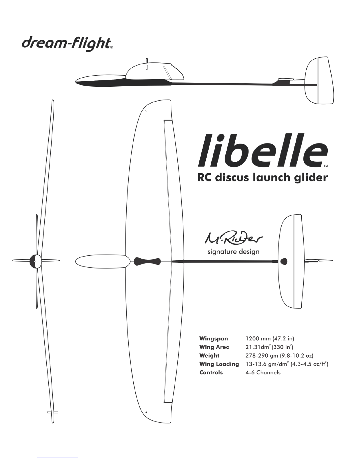
Designer's Notes - The Libelle's 1.2 meter wingspan is user-friendly and easy to transport (designed to fit across
most automobile rear cargo spaces). When compared to the conventional 1.5 meter DLGs, the Libelle's compact
wing gives a little more ground clearance for those pilots just developing their discus launch technique. The Libelle
packs in a lot of wing area by utilizing a lower aspect ratio wing tuned for slow, turning flight- perfect for
thermalling at low altitude like a bird! We started from the ground up, fusing in-house airfoil and wing design to
provide the Libelle with a wide speed range, great launch performance, and efficient flight behavior. Generous
control surfaces provide a nimble control feel that will satisfy even the most experienced pilots.
“Libelle”- Why the Name?
Here in the Goleta Valley, we are fortunate to share the air with
a very wide variety of flying creatures. One of our favorites, the
Green Darner dragonfly, began to appear quite often both
physically and symbolically during the development of the
Libelle. Watching these dragonflies catch even the slightest bit of
air current or lift while not moving their wings was greatly
inspiring. The nimble flight characteristics and beautiful shapes
resonated deeply with our mindset. It could not have evolved
more organically... Libelle- the word for dragonfly in German.
"Libelle" - German for Dragonfly


CAUTION! READ BEFORE PROCEEDING:
►The Libelle R/C glider is not a toy; a certain amount of experience and practice is required to
safely fly this model. We recommend consulting an experienced R/C pilot before attempting to
fly this glider. With proper instruction, learning to fly R/C gliders can be a safe and extremely
rewarding activity.
►ALWAYS fly model aircraft, such as the Libelle, in open areas away from overhead
power/telephone lines, groups of people, trees, roads, buildings, and airports.
►BE CONSIDERATE AND RESPECTFUL! Always be considerate of passersby, spectators, and
other pilots by maintaining a safe distance between them and your aircraft during flight.
Choosing a designated safe landing zone is good practice and always give larger, heavier flying
models the right of way. Treat flying sites with the utmost of respect and care, as future access to
them is by no means guaranteed.
►The discus launch method places a certain amount of physical stress on one's body and glider.
Please proceed with caution when attempting this launch method.
►Avoid over-speeding the Libelle by entering "terminal" style vertical dives or applying
excessive force during launch, as these actions could result in airframe failure and/or personal
injury.
►The Libelle must be assembled, balanced, and trimmed properly to ensure smooth, efficient
flight. Poor balance and trim WILL lead to poor flight characteristics.
►Do not store glider in areas of excessive heat, as this may cause foam parts to warp/deform,
thus adversely affecting the flight characteristics. Additionally, never place objects/weight on
glider during storage and transport unless foam parts are properly supported to prevent
warping.

TABLE OF CONTENTS
Pg. Topic
1 Kit Contents
2 Items Required for Completion (not included)
3 Radio Gear Setup
5 Wing Assembly
10 Fuselage and Tail Assembly
15 Wing Installation
16 Balancing the Libelle: CG Position
17 Control Surface Deflections
18 Pre-Flight Check
19 Test Flights: Trimming for Straight and Level Flight
20 Programming Mixes: from Launch to Thermal
Using Flaps via Flaperons
Active Camber Control via Elevator-Flap Mixing
21 Discus Launch Technique
23 Fine-Tuning CG Position
24 “Urban Soaring” Technique
Background
Important guidelines to follow when flying the Libelle
Slope Soaring
Flatland Soaring
To familiarize yourself with the assembly process, we recommend
reading over this manual before proceeding with final assembly.
When assembling your Libelle, make sure to check
out the HOT TIPS found throughout this manual!

KIT CONTENTS
ITEM
DESCRIPTION
1
Fuselage and Canopy
2
Wing Panels (Left/Right)
3
Horizontal Stabilizer/Elevator
4
Vertical Fin/Rudder
5
Elevator/Rudder Pushrods
6
Manual
7
Small Hardware Bag Contents:
(2)Wing Dihedral Braces (Front/Rear)
Wing Center Plate
(3) Nylon Bolts for Wing and Stabilizer: 20mm, 15mm, 10mm
(2) Aileron Pushrods
(4) Control Horns
(4) Clevises with micro screws
Carbon fiber launching peg
1.
Spare Parts
available at
dream-flight.com

ITEMS REQUIRED FOR COMPLETION (not included)
Radio Gear:
Programmable 6 channel radio system with flaperon mixing (see chart for transmitter suggestions)
Micro receiver, 4-6 gram weight (see chart below for receiver suggestions)
(4) Sub-micro servos (Part DFFA005 recommended, or purchase our Libelle flight pack, Part DFFA007)
(2) Lightweight aileron extensions, 120mm long (Part DFLB109)
Receiver battery: 4.8V 300mAh 1/3AA NiMH (Part DFFA001)
Adhesives and Tape:
Medium instant glue (“CA” or Cyanoacrylate glue)
Hot glue gun (use only low temperature craft variety)
20-25mm (1”) wide painters masking tape –we like the blue or green stuff by 3M!
20mm (3/4”) wide clear, non-yellowing office tape
Tools and Extras:
Small screwdrivers (both Phillips and flathead styles)
Small wire or nail clippers
Small needle-nose pliers
Scissors and sharp hobby knife
Ruler or measuring tape
Right angle (90º) square
Thin permanent marker
Small balance weights - try our non-lead Steel Balance Weights (Part DFAA002)
Paper towels for cleaning glue excess
A bit of fine grit sandpaper
Optional:
Wing reinforcement decal (Part DFLB111)
Double-sided tape for servo and radio gear installation (thin variety without foam)
Packing tape and strapping tape for airframe reinforcement and repair
Acrylic paints - add your personal style! Remember to clean foam with denatured alcohol first.
Suggested Transmitters and Receivers:
Transmitters
Receiver
Futaba
T6J, *T8J
*R2106GF
Hitec
Optic 6 Sport, Aurora 9
Minima 6L
*We used the Futaba T8J 2.4GHz transmitter
and Futaba R2106GF receiver for our own
setup. The R2106GF receiver's extremely short
antenna makes installation a breeze! The T8J
transmitter features a special built-on antenna
for durability, and boasts easy to use, yet very
comprehensive, programming features.
2.

RADIO GEAR SETUP
►Our setup and installation guide is based on the use of our 4.3g digital servos (Part DFFA004). We have
included the exact measurements needed to recreate our setup if you choose another brand of servo.
Additionally, we highly recommend using a programmable radio with flaperon mixing.
Note: Have tools accessible throughout assembly. Only glider parts, adhesives, etc are listed in the "Gather Items
Below" section.
Gather items below:
Transmitter (battery fully charged)
Micro receiver
(4) Servos with 4 skinny servo arms (Part DFFA005)
(2) Lightweight aileron extensions, 120mm long (Part
DFLB109)
4.8v, 300mAh receiver battery (fully charged)
1. Gather four skinny servo arms. Place tiny screws in a
safe place.
2. Using small wire clippers, trim away one side of all
four skinny servo arms as shown.
3. Trim two servo arms to have only one hole remaining,
as shown (these will be used for the elevator and
rudder servos). For the aileron servos, trim the two
remaining servo arms down to two holes as shown. If
desired, sand or file down the sharp corners.
4. Attach aileron extensions to two servos.
5. Turn on transmitter and plug battery into receiver
(observe proper polarity!).
6. Activate flaperon mixing (consult your radio manual
for details).
7. Connect all servos to appropriate receiver channels.
Confirm system is bound and servos are responding.
8. Ensure all trims and sub-trims are centered and set to
zero.
3.

9. Arrange servos on table and attach shorter servo arms to elevator and rudder servos. Attach longer servo
arms to aileron servos. IMPORTANT: Servo arms must be installed in the orientations shown below to
ensure proper function.
10. Referring to graphic below, check for correct servo rotation direction. If needed, reverse servo directions
using transmitter.
11. If necessary, adjust sub-trims so servo arms are at 90 degrees as shown.
12. With a bit of tape, label each servo for future reference during installation (i.e. LA, RA, E, R).
13. Re-install four tiny screws to secure each servo arm.
14. Unplug servos from receiver and power down transmitter and receiver.
4.

WING ASSEMBLY
►IMPORTANT! Joining the right and left wing panels is the most critical and difficult part of assembly. We
strongly encourage you to practice the steps below first WITHOUT glue. Once you are comfortable with the
steps, proceed with glue.
Gather items below:
Wing Panels (Right/Left)
Dihedral Braces (Front/Rear)
Wing Center Plate
(2) Control horns
(2) Aileron servos
(2) Aileron servo extensions
(2) Aileron pushrods
(2) Adjustable clevises with clamping screws
Masking tape
20mm (3/4”) wide clear, non-yellowing office tape
Medium instant glue
Paper towel
1. Enhance control response and reduce servo load by making 20mm-long incisions along foam hinges using a
sharp hobby knife. Alternate, leaving approximately 15mm of intact hinge material between incisions
(imagine a dashed line cut pattern as shown below). Make sure to leave 20mm of intact hinge material also
at each end of control surface. Flex foam ailerons 45 degrees in each direction 10-15 times to loosen hinge
action. Feel free to prepare the hinges on Horizontal Stabilizer and Vertical Fin in same manner (set these
aside for later).
5.

2. Place right and left wing panels on table as shown below, upside down with wing roots (centers) aligned
with edge of table.
3. Apply masking tape to flat side of each dihedral brace as shown. Tape should be slightly longer than each
brace.
4. Apply a small bead of medium instant glue to front and rear dihedral brace recesses on bottom of left
foam wing panel as shown.
5. Insert longer Front Dihedral Brace into molded dihedral slot in left foam wing and press firmly in place.
Using your finger, secure masking tape over glue joint, ensuring brace is flush in wing. Install shorter Rear
Dihedral Brace in same manner as shown below.
6.

6. Apply medium instant glue to areas of right foam
wing shown in graphic to the right. Glue is
applied to the following locations on right wing
only: molded recesses for dihedral braces,
alignment tab recesses, and adjoining wing root
face areas. Avoid applying glue excessively.
7. Pick up left wing with pre-installed dihedral
braces and join with right wing by lowering it
into position, allowing dihedral braces and foam
alignment tabs to locate and align. Press wing
joint together. Using your finger, smooth over pre-
applied masking tape to lock wing panels and
dihedral braces in position and contain excess
glue.
8. Flip wing over and press center joint together as
shown. Ensure wing panels are in proper
alignment and hold for 15-20 seconds. While
supporting wing carefully, inspect entire center
wing joint. Continue to apply pressure to center
wing joint ensuring a tight joint and good
adhesion.
9. As shown in the sequence below, apply medium
instant glue to molded recess for Wing Center
Plate. Apply glue to flat area of recess as well as
deeper perimeter channel. Lay one wing half flat
against table while supporting the raised wing
with one hand to maintain dihedral. Now firmly
press Wing Center Plate in place, applying
pressure for 15-20 seconds as shown.
7.

10. Wipe away excess glue along entire wing joint and around Center Wing Plate. Turn wing over and
carefully remove masking tape covering dihedral braces.
11. Locate control horn recess on underside of each aileron. NOTE: the two holes on each control horn should
face forward towards the molded servo pockets. As shown below, apply medium instant glue to recess and
press control horn in place, applying pressure for a few seconds until glue has set. Wipe away excess glue.
12. Before proceeding, ensure aileron servos are centered, labeled, and extensions are installed. Test fit aileron
servos in their appropriate molded pockets, with the servo arm oriented vertically and centered.
8.

13. Remove servos and securely re-install using a drop or two of medium instant glue, thin double-sided tape, or
low-temperature hot glue.
14. Press the servo wires and extensions neatly into the provided channels. If you have chosen the Wing
Reinforcement Decal option (Part DFLB111), apply this now. Otherwise, apply a piece of clear packing or
office tape over each servo and extension wires. Wing Decal Tip: For easier application of Wing Reinforcement Decal, mist
the foam wing surface with a spray bottle to allow decal to "float" into position. Use a spray solution of 4 drops of dish soap per
quart, or liter, of water. Once decal is in position, use a combination of your fingers, cloth, or a very soft squeegee to apply pressure
from the middle to the edges (this will remove the solution and allow adhesive to come into contact with foam).
15. Prepare two clevises by folding sides together,
creating a slot where the pushrod will be clamped.
With clevis folded, install small clamping screw
through each clevis. Do not tighten screw at this point.
16. Slide clevis onto end of each aileron pushrod. You
may have to loosen clamping screw slightly to allow
clevis to slide onto pushrod end.
17. Insert wire "Z-Bend" side of each aileron pushrod into
outermost (second) hole of servo arms.
18. Adjust and install clevises to align with outermost hole
of aileron control horns.
19. With aileron servo arm centered, center and align
aileron flight surface with wingtip. Adjust clevises as
necessary and tighten clamping screws until pushrod
is secure. Do not over-tighten clamping screw; when
properly tightened, tip of screw should only protrude
slightly from side of clevis.
9.

FUSELAGE AND TAIL ASSEMBLY
Gather items below:
Fuselage
Horizontal stabilizer/elevator
Vertical fin/rudder
Elevator pushrod
Rudder pushrod (longest)
Elevator and rudder servos
(2) Control horns
(2) Adjustable clevises and clamping screws
Nylon elevator bolt (10mm long)
Medium instant glue
Paper towel
Optional double-sided tape for battery and
receiver mounting
1. If you haven't done so already, prepare rudder
and elevator hinges using the same procedure
described in Step 1of Wing Assembly (Page 5).
This will help enhance control response and reduce
servo load.
2. Install control horns in elevator and rudder as
shown, with holes facing hinge. Apply medium
instant glue to recess and press control horn in
place, applying pressure for a few seconds until
glue has set. Wipe away excess glue.
3. Test fit elevator and rudder servos in fuselage by
sliding into position sideways. Before proceeding,
confirm servo fit, orientation, and servo arm
positions as shown. IMPORTANT: Elevator servo
is slid into place before rudder servo, with servo
arm towards rear as shown.
4. Securely install elevator and rudder servos by applying hot glue or a drop or two of medium instant glue
beneath all four servo mounting tabs. Ensure glue penetrates underneath tabs and servos fit tight against
each other and surrounding foam. Apply a little pressure to servos for several seconds as glue sets.
5. Prepare two clevises for elevator and rudder pushrods.
10.

6. Attach a clevis to each pushrod as shown below.
7. Feed Z-Bend end of shorter pushrod through rear of elevator mount at angle as shown below. Slide pushrod
all the way forward through tail boom for connection with elevator servo arm.
8. Remove elevator servo arm and attach to pushrod Z-Bend as shown below. You may need to use small
needle nose pliers to grab the pushrod. Reinstall servo arm and replace screw. IMPORTANT: Elevator and
rudder pushrods must hang BELOW servo arms for proper clearance.
9. Make note of alignment tab on top of elevator mount. Align horizontal stabilizer on mount and secure with
nylon elevator bolt (10mm-long). Do not over-tighten nylon bolt. If bolt thread feels tight, de-burr tip of bolt
using sandpaper.
11.

10. As shown below, attach clevis to elevator control horn at outermost hole. If necessary, use a small flat-
bladed screwdriver to spread clevis apart. If you are having difficulty, try removing stabilizer to make
clevis connection easier (re-install stabilizer after connection has been made). IMPORTANT: Clevis must be
installed with correct orientation (screw head on right side of tail boom) for sufficient pushrod
clearance. You may need to loosen clevis clamping screw to allow pushrod to slide freely in clevis for
adjustment. Do not tighten clamping screw yet.
11. As shown below, test fit vertical fin onto tail boom. Note foam index tab on fin which aligns with tail boom,
providing correct positioning.
12. When gluing fin onto tail boom, ensure fin is mounted at 90 degrees to horizontal stabilizer. Apply
medium instant glue to cutout in vertical fin as shown below. You can substitute 5-minute epoxy for more
working time and a stronger joint. Lightly press vertical fin onto tail boom while aligning index tab with tail
boom cutout. Looking from rear of glider as shown below, ensure fin is mounted 90 degrees to horizontal
stabilizer using a 90º square - adjust fin as needed before glue sets! When fin is perfectly vertical, apply
pressure to glue joint for several seconds or use painter's tape to hold fin in place while glue cures. Wipe
away any excess and allow glue to cure for several minutes before proceeding.
12.

13. For added strength, apply a small strip of clear tape over tail boom and overlapping onto fin (see below).
The tape should not cover pushrod cutout in carbon tail boom.
14. Feed Z-Bend end of longer rudder pushrod into rear opening of carbon tail boom as shown below. Slide
pushrod all the way forward through tail boom for connection with rudder servo arm.
15. Attach clevis to rudder control horn at innermost hole. IMPORTANT: Clevis must be installed with correct
orientation (screw head on top) for sufficient pushrod clearance. You may need to loosen clevis clamping
screw to allow pushrod to slide freely in clevis for adjustment and connection with rudder servo arm. Do not
tighten clamping screw yet.
13.

16. Remove rudder servo arm and attach to pushrod Z-Bend. Re-install servo arm and replace screw as shown
below. IMPORTANT: Elevator and rudder pushrods must hang BELOW servo arms for proper clearance.
17. Ensure elevator and rudder servo arms are centered on servos as shown below.
18. Loosen clevis clamping screws to allow pushrods to slide freely in clevises. Center foam elevator and rudder
control surfaces by eye and tighten clevis clamping screw to lock pushrod in centered position.
19. As shown below, set battery and receiver temporarily in position and plug elevator and rudder servos into
appropriate receiver ports. Twist elevator and rudder servo wires together for a neater installation.
IMPORTANT: Keep your servo and battery wires tidy so as not to obstruct movement of servos and
pushrods.
14.

WING INSTALLATION
Gather items below:
Completed wing
Completed fuselage with tail group installed
Canopy
(2) Wing bolts (20mm front, 15mm rear)
Carbon fiber launching peg
1. Press wing onto fuselage by aligning wing with anti-
rotation pins on fuselage wing saddle.
2. Aileron extension leads should pass through molded
foam channel underneath the wing's leading edge.
Ensure no wires are pinched between the wing and
fuselage. Twist aileron leads together for a tidier
installation.
3. Install two nylon wing bolts. Insert longer 20mm-long
bolt in forward hole. Do not over-tighten nylon bolts;
only slight pressure is needed to hold wing onto
fuselage, since the anti-rotation pins absorb the stress
of discus launching. De-burr ends of nylon bolts with
sandpaper if they feel tight initially.
4. Plug aileron servo leads into appropriate ports on
receiver.
5. IMPORTANT: Install all servo and battery wires in a
neat manner so that they allow canopy to seat
properly and do not obstruct movement of pushrods.
Refer to picture at right for example of a tidy radio
gear installation.
6. Install carbon fiber launching peg in desired wingtip.
Do not force! If peg fit is too tight, sand peg diameter
until it slides in place. If fit is loose, follow the "Hot Tip"
at the bottom of page 21. Most right-handers prefer a
launching peg in the left wingtip; however, there are
those who prefer to launch from the right wingtip (left
hand launch) to keep their right hand on the
elevator/aileron joystick (for Mode 2 transmitters).
15.
Other manuals for Libelle
1
Table of contents
Other Dream-Flight Toy manuals
Popular Toy manuals by other brands

Hasbro
Hasbro Playskool Heroes Transformers Rescue Bots High Tide Rescue... Assembly instructions adult assembly required

GRAUPNER
GRAUPNER Junior Line Series instruction manual

Eduard
Eduard 32 1002 Assembly instructions

REVELL
REVELL F9 F-4/5 PANTHER Assembly manual

Mantua Model Group
Mantua Model Group President 792 Assembly instructions

E-flight
E-flight Mini Funtana Assembly manual