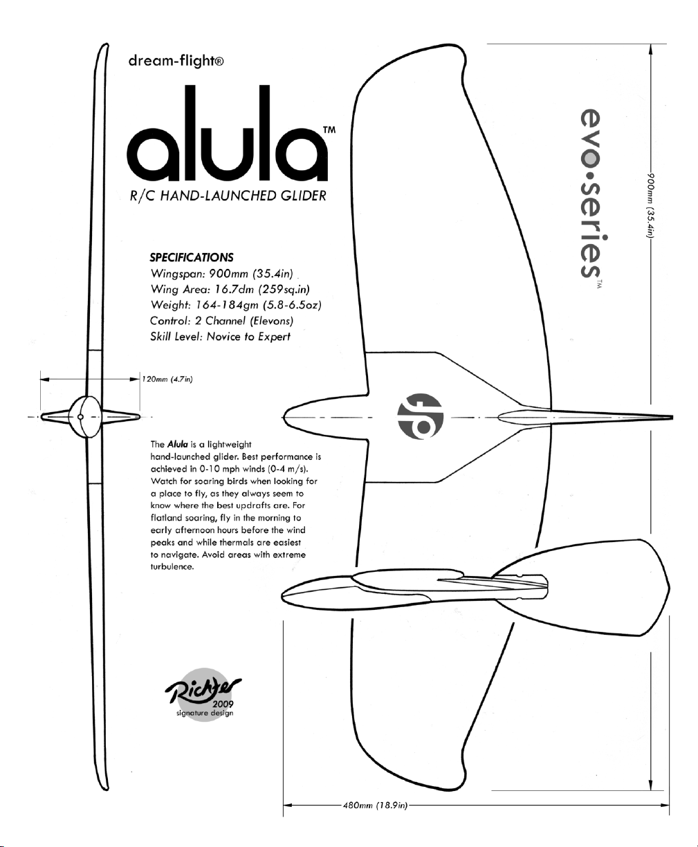
Dream-Flight Alula Evo User manual

INSTRUCTION MANUAL
dream-flight®

About the Alula
This design, inspired by the local red-tailed hawks that frequent the sky above
our workshop, is in reality a very functional glider. Often overlooked is
the forward swept wing configuration utilized by many birds
during soaring flight. This configuration is perfect for a hawk
flying slow, tight circles to stay within small, near ground
thermals while searching for its next meal.
Not only does the Alula’s forward sweep allow you to
navigate small, confined sources of lift like a soaring bird,
but it also eliminates tip stalling and maintains good control surface authority even at very low speeds. The Alula
was designed specifically with the side-arm launch method in mind, since this is a more effective way to launch a
glider by hand. The forward-swept wing facilitates the side-arm launch method by aligning the launch point
(wingtip) with the Center of Gravity. This, coupled with the large tail fin, reduces the twisting tendency of a glider
upon launch, making for straighter, easier flings to altitude.
We call the Alula our "urban glider," due to its ability to soar in the most unconventional of locations. No high-
starts, motors, or spinning propellers required... just fling and fly. It’s as close to an R/C boomerang as it gets!
What’s New?
We’ve been experimenting with swept forward designs on and off over the last ten years but it wasn’t until 2004
that we refined the Alula design as a side-arm launched glider and made it available for purchase. The first
Alulas were hand-cut, and since then our business and products have steadily evolved. In an effort to modernize
our operation, we’ve switched to a molded manufacturing process, which allows us to minimize material usage and
achieve a more refined product. The Alula design has been completely overhauled. It now employs a computer-
designed modular ARCEL foam airframe that can be built as one piece for maximum strength and simplicity or as
a collapsible version for easy travel and storage. All parts were redesigned so that the use of adhesives is
minimized, making assembly a breeze and reducing health/environmental hazards. Further versatility,
aerodynamic and aesthetic refinements, and simplified assembly are hallmarks of the new evo-series gliders. They
demonstrate R/C soaring, evolved.
“Alula” -Why the Name?
We understand that we have a knack for coming up with some
pretty unusual names for our gliders. We love birds and as a
result we stumbled onto the word “alula” while looking through
bird anatomy books for inspiration. The name simply stood out
due to its simplicity and symmetry (it’s a palindrome and thus can
be read the same forwards and backwards). Officially
pronounced “al-you-la” in the birdworld, we like the sound of “ah-
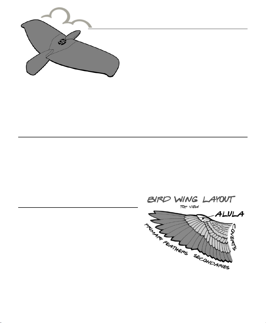
loo-la” when referring to our glider. Upon researching further, we
learned that the “alula” on a bird wing (see figure to the right) is a
set of feathers attached to the bird’s equivalent of a thumb. These “thumb
feathers” on a bird serve as a quasi leading edge slotted flap that helps to delay the
onset of a stall. It works by reinvigorating the airflow over the top of the wing at high angles of
attack. This serves the bird well during take-off, landing, and perching in difficult locations. Simply put, we
thought this name fitting due to the low speed performance of this little glider and its bird-like appearance. Given that
many of us use our thumbs to control our R/C aircraft, this little glider provides us with some “thumb feathers” of our
own.


IMPORTANT! READ BEFORE PROCEEDING:
►The Alula R/C glider is not a toy; a certain amount of experience and practice
is required to safely fly this model. We recommend consulting an experienced
R/C pilot before attempting to fly this glider. With proper instruction, learning to
fly R/C gliders can be a safe and extremely rewarding activity.
►ALWAYS fly model aircraft, such as the Alula, in open areas away from
overhead power/telephone lines, trees, roads, buildings, and airports.
►BE CONSIDERATE AND RESPECTFUL! Always be considerate of passersby,
spectators, and other pilots by maintaining a safe distance between them and
your aircraft during flight. Choosing a designated safe landing zone is good
practice and always give larger, heavier flying models the right of way. Treat
flying sites with the utmost of respect and care, as future access to them is by no
means guaranteed.
►The Alula must be assembled, balanced, and trimmed properly to ensure
smooth, efficient flight. Poor balance and trim WILL lead to poor flight
characteristics. Additionally, make sure to observe proper control surface
deflections that suit your skill level. Flying wings like the Alula usually require a bit
of fine-tuning to achieve the best flight characteristics, so don’t be discouraged if
it takes you a few flights to get it just right.
►Do not store glider in areas of excessive heat for extended periods of time.
Excessive heat may cause foam parts to warp/deform, thus adversely affecting
the flight characteristics. Additionally, never place objects/weight on glider
during storage and transport unless foam parts are properly supported to
prevent warping.

TABLE OF CONTENTS
PG. TOPIC
1 Kit Contents: Parts List and Diagram
2 Items Required for Completion (not included with kit)
Radio Gear
Building Supplies (Adhesives & Tools)
3 Preparing Parts for Assembly
4 Installing Carbon-Fiber Spars
5 Attaching Control Horns
6 Trimming Plastic Belly Skid
7 Installing Radio Gear, Programming Transmitter/ Controller
10 Attaching Wings to Body
11 Installing Antenna
13 Installing Pushrods
15 Applying Grip Tape to Wingtip for Side-Arm Launch Method
16 Balancing the Alula
18 Setting Control Rates
19 Pre-Flight Check, Test Flying
20 Side-Arm Launch
21 Optional Three-Piece Wing Add-on Kit
23 Fine-Tuning Your Alula for Optimum Flight Performance
25 “Urban Soaring” Background and Technique
26 Notes and Color Scheme Layout Page
To familiarize yourself with the assembly process, we strongly
recommend reading over this manual before proceeding.

PART
DESCRIPTION
QTY
MANUFACTURED IN
A
Center Wing Section With Embedded Carbon Spar, i.e.
Fuselage (ARCEL foam)
1
USA
B
Right Wing Panel (ARCEL foam)
1
USA
C
Left Wing Panel (ARCEL foam)
1
USA
D
Fin, i.e. Vertical Stabilizer (ARCEL foam)
1
USA
E
Plastic Belly Skid (PVC)
1
USA
F
Carbon-Fiber Wing Spars, 12.9 in (327 mm)
2
USA
G
Carbon-Fiber Pushrods, 4.5 in (115 mm)
2
USA
H
Black Nylon Wing Joiner Tubes, 1.75 in (45 mm)
2
USA
I
Lightweight Pushrod Links
2
Great Britain
J
Lightweight Flex Control Horns
2
Great Britain
K
Plastic Assembly Tape
1
USA
L
Grip Tape for Wing-Tip Launching
1
USA
M
Decals
3
USA
N*
*Optional 3-Piece Wing Add-On Kit (purchased separately)
(includes 8 magnets, 2 aluminum couplers, and 1 hex key)
-
China, USA
--
Assembly Manual
1
USA
KIT CONTENTS
Parts List and Diagram
-1-

ITEMS REQUIRED FOR COMPLETION (not included with kit)
Radio Gear:
Radio transmitter with Elevon or V-tail mixing and adjustable rates (i.e. control throws)
(Hitec Neon single stick radio with ATV upgrade is a good entry-level transmitter)
2 x sub-Micro Servos, less than 7 grams each (Blue-Bird BMS-306BB, or similar weight/size servos)
Sub-micro Receiver
(Mikro5 receiver for economy and minimal weight)
Rechargeable 4.8V Battery Pack for Receiver
(4.8V 300mAh 1/3AA-size NiMH flat pack, or equivalent)
Adhesives and Paint
Medium or Thin Instant Adhesive (Cyanoacrylate, i.e. CA)
Tape: Painter’s masking tape, Strapping Tape for airframe reinforcement.
Optional Paint for decoration
(Acrylic paints and Sharpie™markers are great for easy decorating of foam surfaces. We like
“Tamiya Color For Plastics” TS series spray paint for foam parts and clear plastic belly skid part.)
Tools and Extras
Sharp scissors
Steel ruler for measuring
Sharp hobby knife or razor blade
Small curved scissors for trimming plastic belly skid- Inexpensive nail trimming scissors are great and can
be found at most drug and pharmacy stores. Lexan scissors are also well suited.
Small screw drivers
Small flush-cutting pliers or nail clippers
Pencil, ball-point pens, and fine-point Sharpie marker
Coins and/or small weights for balancing glider
150 and 220-320 grit sandpaper
Optional Dremel™ tool (i.e. rotary cutter/grinder)
-2-
IMPORTANT! Read this before assembling your Alula:
►For lowest weight and best light lift performance use minimal paint and omit installing the three-piece wing add-
on kit.
►Do not cover large portions of the foam airframe with any sort of film (iron-on, tape, vinyl, etc), as this will result
in an overweight glider.
►Apply tape to entire perimeter of belly skid to ensure maximum fuselage strength! Failure to do so may result in
fuselage breakage during hard launches and landings. TIP: Apply fiber-reinforced strapping tape under belly skid
for added strength.
►If you decide to utilize the three-piece wing option and plan to do a lot of vigorous side-arm launching, we
recommend adding some tape to the wing joints before flying.

ALULA BUILDING INSTRUCTIONS
1) Preparing Parts for Assembly: Remove parts from box.
2) Locate foam wings (Parts B and C). Using fine sandpaper
(220-320 grit), sand away any excess foam “flash” that
has squeezed past perimeters of parts during the molding
process. See Figure 1. The most crucial areas are located
along perimeter of wings’ lap joints, as any excess “flash”
here will prevent wings from mating properly with
fuselage section. There is usually a small amount of flash
along leading and trailing edges of wings, so make sure
to check these areas with your finger and sand lightly as
necessary.
3) It may cross your mind to sand away the small bumps on
the surface of the foam parts. While it is possible to do
this, we now advice against it. It proves to be more work
than it’s worth and the performance of the glider may be
better when the bumps and smooth molded surface are
left intact.
4) To enable control surfaces to pivot freely, use a hobby
knife or razor blade to trim away small 1mm wide sliver
of foam joining control surface and wingtip on both wing
panels. See Figure 2.
5) Gently grab control surface at its widest point and pivot
approximately 45 degrees in both directions. This should
be done 15-20 times to loosen the hinge action. Don’t
worry about breaking hinge –it is tougher than you think!
Repeat this step for remaining wing panel.
Figure 1. Removing “Flash”
Figure 2. Freeing Control Surface and Loosening Hinge Action
Flash↓
-3-

6) Installing Carbon-Fiber Spars: Locate two rectangular carbon-fiber spars (F). A spar will be glued into
each 1mm wide channel provided on bottom surface of each wing panel.
7) Using back end of a ball point pen or pencil, firmly press carbon spar into provided channel so that it is
slightly recessed. Make sure end of the spar does not protrude from end of wing which faces fuselage.
See Figure 3.
8) Hold wing so that one end of spar is higher than the other (this allows the glue to better flow along the
channel). Starting at highest point, drip thin instant glue (i.e. “CA” or cyanoacrylate) into spar channel
every 2-3 cm, working your way along entire length of channel. Notice that glue wicks naturally into
channel and around carbon spar. If you notice that glue drop only wicks along one side of spar, make
sure to add some glue to other side. CAUTION: If excessive glue is applied it WILL run out open end of
channel and may drip onto whatever is below it.
9) Complete steps 6-8 for remaining wing panel.
10) Locate two 45mm (1.75 in) black plastic wing joiner tubes (H). If you would like to assemble wings as
one piece for minimum weight and complexity, proceed to Step 11. If, however, you would like to
utilize the optional three-piece wing add-on kit you purchased separately for easy travel and
storage, refer to page 21.
11) As shown in Figure 4, firmly press each black plastic wing joiner tube (H) into provided channel located
at end of each wing panel. Disregard extra ring of space provide around center of tube, as this is
provided for the three piece wing add-on option. Do not attempt to fill this space surrounding tube
with glue or filler.
12) Apply thin instant glue to exposed sides of tube, allowing it to wick down and in between foam and
plastic tube. Do not apply excess glue around ends of the tube. See Figure 4 on the following page.
Using back end of a ball point pen or pencil, firmly press tube down to ensure a good, tight bond
between foam and tube.
Figure 3. Installing Carbon-Fiber Spars
-4-

13) Attaching Control Horns: Locate two black lightweight
flex control horns (J). Notice provided locator
depression on bottom of each foam control surface.
Control horns will be attached at these prescribed
locations. With round coupler portion facing wing spar,
press control horn barbs through foam until fit is tight
(no pre-drilling is necessary). See Figure 5. Excess
barb protruding from opposite side will be trimmed
after gluing.
14) Apply two drops of thin instant glue, one at front of
horn and one at rear of horn so that glue wicks in
between control horn and foam surface. See Figure 5.
Hold firmly in place for 5-10 seconds. Wipe away
any excess adhesive with a paper towel.
15) Turn wing over. Using a pair of nail clippers or flush-
cutting pliers, trim protruding barbs so that they are
even with the foam surface. See Figure 5. CAUTION:
Wear protective eyewear while trimming barbs, as
the excess barbs tend to pop off with great velocity.
For an extra secure hold, place a drop of glue over
each trimmed barb.
16) Repeat Steps 13 - 15 for remaining wing panel and
control horn.
17) Set wings aside and allow instant glue to cure
thoroughly for 15 minutes.
Figure 4. Installing Plastic Joiner Tubes
Figure 5. Attaching and Trimming Flex Control Horns
-5-

Figure 6. Trimming Plastic Belly Skid
18) Trimming Plastic Belly Skid: Locate plastic belly
skid (E). Using curved nail scissors (or Lexan scissors),
first trim flange surrounding base of part. Then trim
part to slightly oversized, using molded cut line as a
guide. If you have difficulty seeing the cut line, use a
fine-point Sharpie marker to “enhance” it for easier
cutting. See Figure 6. Next, sand edges down to
exact perimeter line using sandpaper (150 grit).
Check fit of skid on foam fuselage by pressing it
firmly into place. If necessary, sand perimeter of
plastic skid until fit is good.
19) To cut out center hole for easy access to receiver, use
a Dremel tool with 3mm (1/8 in) side cutting bit or
sanding tip to remove center piece inside designated
line. You can also carefully and slowly score along
designated line using hobby knife or razor blade.
Rotate part to facilitate cutting process. Continue
cutting around score line until center piece releases.
See Figure 6. Sand edges using sandpaper (150
grit). Inside of belly skid may be painted if desired.
We recommend Tamiya’s Color for Plastics TS-series
spray paints.
20) Locate center wing section (i.e. fuselage) (A) and
lightly sand away any excess flash around perimeter
using fine sandpaper (220-320 grit).
21) Locate foam fin (i.e. vertical stabilizer) (D). Sand
away any excess flash around perimeter of foam fin.
The main areas where flash may be visible are
along front curved leading edges and rear edge. A
quick swipe with 220-320 grit sandpaper is all it
usually takes. Do not sand so much as to round
corners off.
22) Test fit of foam fin onto fuselage (A). Note that initial
fit may be tight. Over time, fit will loosen and tape
may be necessary to hold fin securely in place.
23) Decorate glider as you wish, but keep in mind that
paint adds weight. The best method is to use lightweight spray paint such as Tamiya’s Color for Plastics
TS-series. This paint can be found at most hobby stores carrying R/C cars and is known to be safe for
the included foam and plastic parts. Please note that many paints may not be suitable. Apply paint
sparingly in several light coats to provide even coverage. We recommend only adding accent colors to
airframe, as paint adds more weight than you think. A quick and easy way to decorate your airframe
is to use permanent markers or acrylic paints. Allow paint to dry before proceeding.
-6-

Figure 8. Centering of Servos and Layout of R/C Gear
Figure 7. Trimming Servo Arms
24) Installing Radio Gear:
Gather the following items:
-Two Sub-micro Servos (i.e. Blue-Bird
BMS-306BB)
-Fully Charged 4.8V Receiver Battery
(i.e. Dream-Flight 4.8V 300mAh NiMH
pack)
-Sub-micro Receiver of choice
-Transmitter (battery fully charged)
25) If your servos do not include a single-arm
control arm, simply trim off one
extraneous arm from each control arm,
using flush-cutting pliers. See Figure 7.
CAUTION: Wear protective eyewear
while trimming, as excess arms tend to
pop off with great velocity.
26) In order for lightweight pushrod links to
connect to servos, you need the servo
arm hole to be 1.6 mm (1/16 in). If
necessary, enlarge hole that is 10-12
mm from center screw hole using a 1.6
mm (1/16 in) drill bit.
27) Programming Transmitter/Controller:
Turn on transmitter. Enable “Elevon” or
“V-tail” mixing and set all trims to zero.
Set transmitter’s independent elevator
throws to 20% and aileron throws to
60%. This is simply a good starting
point. Please note that very little
elevator travel (i.e. up and down
movement of the control surface) is
required for pitch control. Too much pitch
control will make the glider difficult to
fly. Good rule of thumb: set elevator
(pitch) rate to 1/3 of the total aileron
(roll) rate (i.e. deflection).
28) With transmitter still on, temporarily plug
servos into elevator and aileron ports of
receiver. Now, plug battery directly into
receiver. The servos will center upon
start-up. Before proceeding, check trim
adjustments on transmitter to make sure
manual trims, as well as sub-trims, are set to zero. This will ensure that servos are absolutely centered.
Lay R/C components loosely on underside of fuselage. See Figure 8.
-7-

29) Temporarily press servo arms onto servos and lay back into place. Place fuselage section, bottom side
up and nose pointing away from you, on the table as shown in Figure 9.
30) To achieve correct servo rotation, check the following and refer to Figure 9:
Pull back (down) on transmitter joystick (Glider nose up):
►Both control arms on servos rotate toward tail of glider (towards you).
Push forward (up) on joystick (Glider nose down):
►Both control arms on servos rotate toward nose of glider (away from you).
Push joystick to the left (Glider rolls left):
►Control arm on your right rotates towards you; Left control arm rotates away from you.
Push joystick to the right (Glider rolls right):
►Control arm on your right rotates away from you; Left control arm rotates towards you.
If you are lucky, you will achieve proper rotation on the first try. If not, you may need to swap servo
plugs at the receiver and/or adjust the transmitter’s servo reversing menu. Once you have achieved
correct rotation, lift servos up enough to install screws. This locks servo arms in place. Press servos back
into their compartments.
↑Figure 9. Checking Servos for Proper Rotation ↑
-8-

31) Thread servo wires through provided channels in center fuselage section. Pull wires through to take up
any slack. See Figure 10. If your servo fits loosely, add small shims of cardboard or balsa to tighten
fit. Apply tape over servos to hold them securely.
32) Plug servos back into receiver. Ensure that wiring plug arrangement is the same as before. (Refer to
Step 30.)
33) To achieve minimum glider weight, receiver should be installed as far forward as possible. Servo wire
lead length will determine how far forward you can install receiver. Holding receiver in most forward
position, trace outline onto fuselage as shown in Figure 11.
34) Using a hobby knife, cut along the traced outline as deeply as needed so that receiver will sit just
below flush with fuselage. This allows battery wire to be routed over top of receiver. Cut score lines
across interior if desired for easier removal of material. Scoop out foam so that a hole the size of your
receiver remains. Test fit by inserting receiver. Adjust hole as necessary. See Figure 11. Due to the
Alula’s small size and light weight, no switch will be used. We recommend simply plugging battery
directly into receiver for power. This is done via small oval cut-out located on the skid pad.
Figure 10. Installing Servos
Figure 11. Installing Receiver
-9-

35) Attaching Wings to Body:
1-Piece Option: Slide wing (B or C) onto fuselage (A) by aligning black plastic wing joiner tube with
round carbon-fiber spar. Turn glider over and press parts firmly together to close gap. Using
masking tape, temporarily secure pieces tightly together. See Figure 12. Turn glider upside down
and apply supplied plastic tape (K) along bottom joint in two pieces as shown. Turn glider over and
carefully remove masking tape. Apply plastic tape to full length of top wing joint. Using two pieces
of plastic tape, start at control surface hinge line and work forwards. For a cleaner look, apply a
strip of tape over channel containing plastic wing joiner tube. Repeat for other wing.
3-Piece Option: Slide wing (B or C) onto fuselage (A) by aligning black plastic wing joiner tube with
round carbon-fiber spar until magnets lock and joint is tight. Repeat for other wing. Using supplied
hex key, slowly tighten set screws in aluminum couplers until you feel slight resistance. Then, tighten
no more than an additional ¼ turn (90 degrees). CAUTION: Do not tighten set screw excessively,
as it will cause round carbon spar to split.
Figure 12.
1-Piece Wing Option:
Attaching wings using supplied tape
1. Clamp wing and fuselage together with masking
tape applied across top joint.
2. Apply plastic tape to bottom joint in pieces.
3. Remove masking tape and apply plastic tape to
top joint in pieces.
1.
2.
3.
-10-

36) Installing Antenna:
Depending on your receiver type and antennae wire length, you may want to:
A. Let antenna wire fly freely beyond the rear of the glider.
B. Tape antenna wire in place alongside fuselage body toward fin.
C. Embed long antenna in wing (for 1-Piece wing only). See Figure 13 on the next page. This is the
most aerodynamic installation:
1. Use a 3 mm (1/8 in.) diameter screwdriver to gently poke hole through fuselage side and
into receiver cavity at perimeter line of belly skid.
2. To recess antenna between hole and spar channel, use a sharp hobby knife to cut a
shallow slit into foam on flat side of fuselage body from hole to end of spar. Push antenna
through hole from its original location. Stretch antenna end past tip of spar and
temporarily tape in place. Then, stretch antenna along spar to remove slack.
3. Press antenna into shallow slit using a small flathead screwdriver.
4. Starting at fuselage, tape antenna into place, ensuring that it lies directly inside spar
channel. Extra antenna length can be embedded in wing for enhanced signal reception
and range, but you’ll have to create an additional slit at an angle to the spar, back
towards the fuselage.
-11-

1. Poke hole through fuselage into receiver cavity.
2. Cut slit from hole to spar channel.
3. Tuck antenna into slit.
4. Tape antenna in spar channel and
beyond (If desired)
2.
4.
1.
3.
4.
Figure 13. “C” Long Antenna Installation (1-Piece Wing Only)
-12-

Figure 14. Attaching Pushrod Link
37) Installing Pushrods: Locate two 115 mm
(4.5 in) carbon-fiber pushrods (G) and two
lightweight pushrod links (I). Using instant
glue, attach a lightweight pushrod link to
one end of each pushrod. See Figure 14.
Allow glue to cure for a few minutes
before proceeding.
38) Temporarily secure control surfaces in
neutral position using masking tape. (i.e.
align control surface with rear of fuselage
and wing tips.) See Figure 15. The tape
holds the control surfaces in the proper
position during attachment of the pushrods.
Slide end of pushrod into round coupler
portion of black control horn. Then attach
pushrod link to hole in servo control arm
and snap in place. To remove wings on 3-
Piece version at a later time, simply
disconnect pushrod at servo arm using a
flathead screwdriver to pry open link.
Repeat for other pushrod.
Figure 15. Securing Control Surfaces in Neutral Position with Strips of Masking Tape
-13-

39) Double check to make sure control surfaces remain in neutral positions and then apply one drop of
instant glue to secure each pushrod to corresponding control horn as shown in Figure 16 below. Allow
glue to cure 10 minutes before moving glider. Once cured, gently remove temporary masking tape
securing control surfaces.
Figure 16. Gluing Pushrod to Flex Control Horn
-14-

40) Applying Grip Tape to Wingtip for Side-Arm Launch Method: Locate grip tape (L). Using a hobby
knife or razor blade, cut grip tape in half into two equal pieces.
41) If you are right-handed, grip left wing-tip as if launching, with thumb on top and index finger on
bottom along carbon spar. If you are left-handed, grip right wing-tip instead. Note the locations of
both your finger and thumb tip. Apply a strip of grip tape under your finger and thumb at these
locations to increase your grip during launch. See Figures 17 and 18 below. HOT TIP: For extra
durability, apply a strip of the supplied tape to leading edge of wings. To conform tape to wingtip,
stretch it as you apply it around the curves.
Figure 17. Attach Grip Tape to Top of Wingtip
Figure 18. Attach Grip Tape to Bottom of Wingtip
-15-
Table of contents
Other Dream-Flight Toy manuals
Popular Toy manuals by other brands

Eduard
Eduard Bf 109G-10 interior Assembly instructions

GRAUPNER
GRAUPNER EUROFIGHTER Anleitung

Mega Construx
Mega Construx Pokemon DETECTIVE PIKACHU GGK28 manual

Fisher-Price
Fisher-Price Imaginext N0764 manual

Rapido Trains
Rapido Trains F40PH-2D operating instructions

Pilot Brand
Pilot Brand TANGO-X Flight instruction manual