Druck UNIK 5 00 Series User manual


Copyright 2022 Baker Hughes Company.
English–UNIK 5*00 Series | i
Safety
The manufacturer has designed this sensor to be safe when operated using the procedures
detailed in this manual. Do not use this sensor for any other purpose than that stated.
This publication contains operating and safety instructions that must be followed for safe
operation and to maintain the sensor in a safe condition. The safety instructions are either
warnings or cautions issued to protect the user and the equipment from injury or damage.
Use qualified* personnel and good engineering practice for all procedures in this publication.
Maintenance
The sensor must be maintained using the manufacturer's procedures and these should be
carried out by authorized service agents or the manufacturer's service departments.
Druck.com
For technical advice contact the manufacturer.
WARNING Do not apply pressure greater than the maximum safe working
pressure to the sensor.
* A qualified technician must have the necessary technical knowledge, documentation, special test
equipment and tools to carry out the required work on this equipment.

Copyright 2022 Baker Hughes Company.
ii | UNIK 5*00 Series–English
Symbols
Abbreviations
The following abbreviations are used in this manual.
Note: Abbreviations are the same in the singular and plural.
Symbol Description
This equipment meets the requirements of all relevant European safety directives. The
equipment carries the CE mark.
This equipment meets the requirements of all relevant UK Statutory Instruments. The
equipment carries the UKCA mark.
This symbol, on the equipment, indicates a warning and that the user should refer to the
user manual.
Druck is an active participant in Europe’s Waste Electrical and Electronic Equipment
(WEEE) take-back initiative (directive 2012/19/EU).
The equipment that you bought has required the extraction and use of natural resources
for its production. It may contain hazardous substances that could impact health and the
environment.
In order to avoid the dissemination of those substances in our environment and to diminish
the pressure on the natural resources, we encourage you to use the appropriate take-back
systems. Those systems will reuse or recycle most of the materials of your end life
equipment in a sound way. The crossed-out wheeled bin symbol invites you to use those
systems.
If you need more information on the collection, reuse, and recycling systems, please
contact your local or regional waste administration.
Please visit the link below for take-back instructions and more information about this
initiative.
https://qrco.de/dsweee
Abbreviation Description
°C Degrees Celsius
COSHH Control of Substances Hazardous to Health
FS Full-scale
mA Milli Ampere
mbar Millibar
psi Pound per square inch

Copyright 2022 Baker Hughes Company.
English–UNIK 5*00 Series | iii
Contents
1. Introduction 1
1.1 Manufacturer 1
2. Description 1
2.1 Purpose 1
2.2 Technical Specifications 2
2.3 Design and Principle of Operation 2
2.4 Markings 3
3. Installation & Operation 4
3.1 General Requirements 4
3.2 Safety Measures 4
3.3 Connecting to a Pressure Source 5
3.3.1 Media Compatibility 6
3.3.2 Pressure Containment 7
3.4 Power Requirements 8
3.5 Maintenance 9
3.5.1 Visual Inspection 9
3.5.2 Cleaning 9
3.6 Returned Goods Procedure 9
3.6.1 Safety Precautions 9
3.6.2 Important Notice 9
3.7 Electromagnetic Compatibility 9
3.7.1 Power Supply and Metering 9
3.7.2 Cable Type 10
3.7.3 Earthing (Grounding) 10
3.8 Faults 10

Copyright 2022 Baker Hughes Company.
iv | UNIK 5*00 Series–English

Copyright 2022 Baker Hughes Company.
English–UNIK 5*00 Series | 1
1. Introduction
This manual is applicable to UNIK family pressure sensors consisting of the following product
series:
• UNIK 5000, UNIK 5600, UNIK 5700, UNIK 5800 and UNIK 5900
The original language of this manual is English.
1.1 Manufacturer
The identified manufacturer of this equipment is:
“Druck Limited”
Fir Tree Lane, Groby, Leicester, LE6 0FH, United Kingdom.
Telephone: +44 116 231 7100; Fax: +44 116 231 7103
Internet: Druck.com
Under the instruction of Druck Limited, the pressure sensors may also be manufactured in China
by:
Baker Hughes Sensing & Inspection (Changzhou) Co., Ltd.
Building 9A, Jintong International Industrial Park, No. 8 Xihu Road, Wujin High-Tech
Industrial Zone, Changzhou, Jiangsu 213164, China.
Each sensor is marked to indicate the country of manufacture.
2. Description
2.1 Purpose
UNIK pressure sensors (hereinafter referred to as sensors) are designed for continuous
measurement and conversion of gauge, atmospheric, absolute and differential pressure into an
analogue output signal of direct current or voltage.
UNIK is a family of modern pressure sensors of modular design, the parameters of which are
chosen by the customer at the time of order, see Figure 1.
Figure 1: Modular Design of UNIK Pressure Sensors
The sensors are designed for measurement of pressure in systems.
1 Pressure connector. 2 Pressure measuring module.
3 Partially encapsulated electronics module. 4 Electrical connection.
5 Cylindrical metal housing.
1
2
3
4
5

Copyright 2022 Baker Hughes Company.
2 | UNIK 5*00 Series–English
UNIK pressure sensors are optionally available with certification permitting their use in explosive
atmospheres.
2.2 Technical Specifications
Refer to the appropriate UNIK 5*00 data sheet for technical specifications and explanation of the
product model number.
Model numbers appended with a four or eight-digit alphanumeric string denote the use of a
customer-specific specification drawing indicating the use of additions or deviations to the data
sheet specification. Refer to the specification drawing if applicable.
2.3 Design and Principle of Operation
The sensor consists of a pressure connector, pressure measuring module, a partially
encapsulated electronics module, and electrical connection facilities, structurally combined in a
cylindrical metal housing.
The pressure connector allows the sensor to be mounted to a pressurized vessel or pipework.
The pressure measuring module consists of a welded metal body featuring a metal diaphragm
(providing a flexible barrier to the process media), a glass-to-metal seal (for electrical
connections) and a fluid filled cavity containing a silicon diaphragm with diffusion implanted
resistors arranged in the form of a Wheatstone bridge.
The operating principle of the pressure sensor is based on the piezo resistive effect: a change in
resistance when applying pressure. When pressure is applied, the silicon diaphragm flexes,
changing the resistance of the implanted resistors and the output voltage of the bridge circuit.
For sensors designed to measure ‘gauge’ or ‘atmospheric’ pressure, the rear of the silicon
diaphragm is vented to the external atmosphere via a PTFE filtered port in the body of the
enclosure, or via a tube in the supplied electrical cable.
The electronic circuit, available in three main variants (“PMP”, “PDCR” and “PTX”) provides a
range of electrical connection and electrical output signal options.
Depending on the type of electrical connection facility provided, the 'zero' and 'span' settings of
the sensor can be adjusted.
Depending on the type of electrical output and electrical connection of the sensor, it is possible,
by connecting certain electrical contacts together, to receive an output signal simulating an
external pressure equal to 80% of the full scale. This is the ‘Shunt Calibration’ feature of the
sensor.

Copyright 2022 Baker Hughes Company.
English–UNIK 5*00 Series | 3
2.4 Markings
For typical markings applied to the non-hazardous area version of pressure sensors, see
Figure 2:
Figure 2: Identification, Electrical and Pressure Markings
1. Product name: ‘UNIK 5000’
2. Product description: ‘Pressure Sensor’
3. CAUTION: To install and use this equipment, read, understand and comply with this
document.
4. Accuracy description: Industrial/Improved/Premium
5. Model number
6. Serial number
7. Pressure range limits and unit of measurement
8. Input supply voltage range and current limits
Note: The symbol indicates the use of direct current
9. Output voltage or current range
10. Ambient temperature range
11. Reserved for applicable certification markings. Position on sensor may vary
12. Manufacturer's name and address
13. Country of manufacture
UNIK 5000
PRESSURE SENSOR
#### 50## - T* - A* - C* - H* - **
********** ACCURACY
S/N ********
*** TO *** *** *
Supply: *** TO *** V *** mA
Output: *** TO *** ** ********
Temp. Range: *** TO *** °C
DRUCK LTD. GROBY, LE6 0FH, UK
MADE IN *****
[1]
[2] [3]
[4]
[5]
[6]
[7]
[8]
[9]
[10]
[11]
[12]
[13]

Copyright 2022 Baker Hughes Company.
4 | UNIK 5*00 Series–English
3. Installation & Operation
3.1 General Requirements
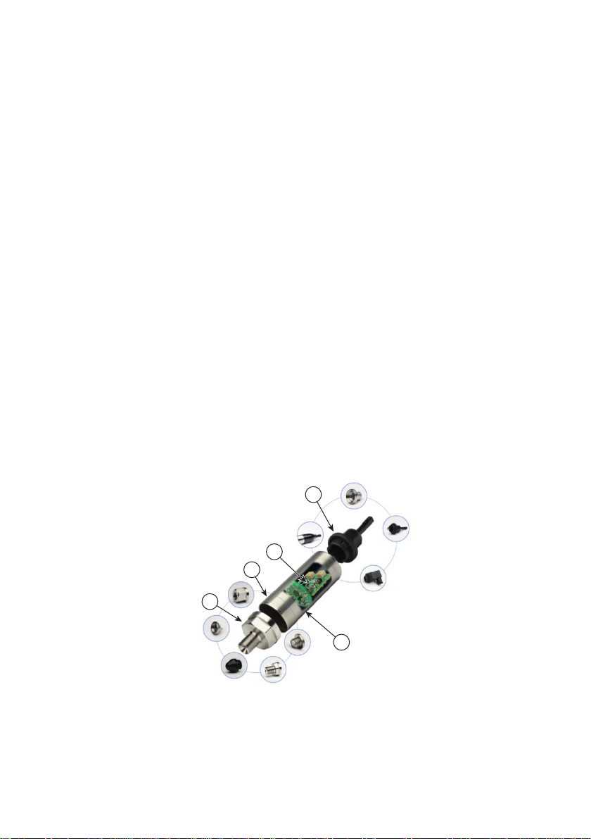
When the sensor is received, check the completeness.
To identify the electrical and pressure connections, refer to the product datasheet or, if applicable,
the specification drawing.
Do not use force when installing the sensor. Use only a wrench on the sensor’s hexagonal flats
to tighten the sensor.
The ambient temperature and the process media to be measured must not exceed the ranges
specified in the sensor specification.
Do not use the sensor where the pressure medium may freeze. This may cause damage to the
sensor and connected pressure equipment.
The materials used for the primary enclosure and pressure bearing surfaces are identified in the
product datasheet or, if applicable, the specification drawing. Make sure that the materials are
applicable for the installation.
Before using the equipment, remove the plastic/rubber protection cap from the pressure
connector.
Some models feature a white PTFE vent filter in the wall of the enclosure. Make sure the vent
filter is correctly installed and is flush with the enclosure body.
3.2 Safety Measures
The operation of sensors in systems whose pressure may exceed the overload values specified
in the data sheet or customer-specific specification drawing is not allowed.
Connection and detachment of sensors from the mains supplying the pressure of the medium to
be measured must be done after the shutoff valve is closed from the process and the pressure in
the working chamber is made equal to atmospheric.
The connecting pipes must have a one-way slope (not less than 1:10) from the pressure collection
point up to the sensor, if the medium to be measured is gas, and down to the sensor if the medium
is liquid. If this is not possible, when measuring gas pressure at the lower points of the connecting
lines, it is necessary to install sludge vessels, and when measuring the liquid pressure at the
highest points, install gas collectors.
Selected devices for mounting sensors should be mounted on straight sections, at the maximum
possible distance from pumps, locking devices, elbows, expansion joints and other hydraulic
devices. It is especially not recommended to install sensors in front of the shut-off device if the
CAUTION Until installation, keep the unit in the original container with all the
covers in position. The container and covers prevent contamination and
damage. When not in use, keep the connections covered.
WARNING High pressures, temperatures and potentially poisonous pressure
media are dangerous, and can cause injury to personnel and damage to property
and the environment. Ensure correct installation, sealing of pressure interfaces
and connection of the equipment. Ensure correct operation of the equipment in
accordance with the specification. Use the applicable protection and obey all
safety precautions.
WARNING For sensors intended for use in Explosive Atmospheres refer to
additional instructions on Hazardous Area Installation.

Copyright 2022 Baker Hughes Company.
English–UNIK 5*00 Series | 5
medium to be measured is liquid. If there are water hammers in the system, it is recommended
to use a sensor complete with a hydraulic shock dampener.
To reduce the temperature acting on the isolation diaphragm when measuring vapor pressure, it
is recommended to use impulse tubes. The impulse tube must first be filled with water.
Attach the equipment in a safe configuration that prevents unwanted stress (vibration, physical
impact, shock, mechanical and thermal stresses). Do not install the equipment where it can be
damaged by a material that causes corrosion. Provide additional protection for the equipment if
it may be damaged in service.
When installing power supply and signal wiring, the possibility of condensate entering the sensor
cable entry should be avoided.
3.3 Connecting to a Pressure Source
When mounting the sensor, seal the mating surfaces. Failure to properly seal may affect
performance or calibration accuracy.
Male threaded pressure connectors must not be sealed or constrained against the face at the
base of the thread. The forward cone or flat face should always be used as indicated below.
98

Copyright 2022 Baker Hughes Company.
6 | UNIK 5*00 Series–English
3.3.1 Media Compatibility
The media compatibility of the product is shown in Table 1.
Table 1: Media Compatibility
Product Pressure Range Media Compatibility
5000 0 –200 bar (0 –2900 psi) Fluids compatible with stainless steel 316L and
Hastelloy C276.
201 –500 bar (2915 –7250 psi) Liquids and group II gases compatible with
stainless steel 316L (and stainless steel 17-4PH
for pressure connector P58 only).
501 –700 bar (7265 –10150 psi) Group II liquids and group II gases compatible
with stainless steel 316L (and stainless steel
17-4PH for pressure connector P58 only).
Notes:
For the wet/dry differential version, negative
pressure port: Fluids compatible with stainless
steel 316L, stainless steel 304, Pyrex, silicon and
structural adhesive.
For pressure connector option PW: immersion
fluid must be compatible with Kynar.
For electrical connector option 3: immersion fluid
must be compatible with polyurethane.
For electrical connector option 4: immersion fluid
must be compatible with Hytrel.
For electrical connector option N: immersion fluid
must be compatible with Kynar.
5600 0 –200 bar (0 –2900 psi) Fluids compatible with stainless steel 316L (and
Hastelloy C276 for differential versions only).
201 –500 bar (2915 –7250 psi) Liquids and group II gases compatible with
stainless steel 316L.
501 –700 bar (7265 –10150 psi) Group II liquids and group II gases compatible
with stainless steel 316L.
Notes:
For the wet/dry differential version, negative
pressure port: Fluids compatible with stainless
steel 316L, stainless steel 304, Pyrex, silicon and
structural adhesive.
For pressure connector option PW: immersion
fluid must be compatible with Kynar.
For electrical connector options N and P:
immersion fluid must be compatible with Kynar.
For electrical connector options U and V:
immersion fluid must be compatible with TPE-U.
For electrical connector options P and V:
immersion fluid must be compatible with nitrile
butadiene rubber.

Copyright 2022 Baker Hughes Company.
English–UNIK 5*00 Series | 7
Note: Fluid classification complies with European Regulation (EC) No 1272/2008 and GB CLP
Regulation, UK S.I. 2019/720. Statements comply with European Pressure Equipment Directive
2014/68/EU and UK S.I. 2016/1105; amended by S.I. 2019/696. Refer to document K0581 for
product classification and regulatory information.
3.3.2 Pressure Containment
The pressure containment of the sensors is shown in Table 2.
5700 Fluids compatible with titanium grades 2, 4 and 5.
Notes:
For pressure connector option PW: immersion
fluid must be compatible with Kynar.
For electrical connector options N and P:
immersion fluid must be compatible with Kynar.
For electrical connector options U and V:
immersion fluid must be compatible with TPE-U.
For electrical connector options P and V:
immersion fluid must be compatible with nitrile
butadiene rubber.
5800/5900 0 –200 bar (0 –2900 psi) Fluids compatible with stainless steel 316L and
Hastelloy C276.
201 –500 bar (2915 –7250 psi) Liquids and group II gases compatible with
stainless steel 316L.
501 –700 bar (7265 –10150 psi) Group II liquids and group II gases compatible
with stainless steel 316L.
Table 2: Pressure Containment
Product Pressure Range Pressure Containment
5000/5600/5700 0 –150 mbar (2 psi) 10 × FS
0–70 bar (1000 psi) gauge 6 × FS (200 bar (2900 psi) maximum)
0–70 bar (1000 psi) absolute 200 bar (2900 psi) maximum
>70 bar (1000 psi) 1200 bar (17400 psi) except for pressure
connector options PX, RA and RF which are
limited to 600 bar (8700 psi)
Note: Differential (–ve port) must not exceed
positive port by more than 6 × FS (15 bar
(200 psi) maximum).
5800/5900 0 –50 bar (725 psi) gauge 6 × FS (200 bar (2900 psi) maximum)
0–50 bar (725 psi) absolute 200 bar (2900 psi) maximum
>50 bar (725 psi) 1200 bar (17400 psi) maximum
Table 1: Media Compatibility (Continued)
Product Pressure Range Media Compatibility

Copyright 2022 Baker Hughes Company.
8 | UNIK 5*00 Series–English
3.4 Power Requirements
The sensor should be connected to a compliant stable power supply. The power supply must be
energy-limited to a maximum of 4.2 A. The power supply requirements for the sensor are shown
in Table 3 and Table 4.
Table 3: Supply Voltage
Product Output Type Supply Voltage
5000 PMP (Basic) 7 to 32 Vdc (12 to 32 Vdc for 0 to 10 V Output)
PMP (Ratiometric) 5 ± 0.5 Vdc
PMP (Basic Configurable) (Maximum Output + 1 V) (7 V Minimum) to 32 V
PMP (Configurable 3 & 4 wire) 7 to 36 Vdc
PTX 7 to 32 Vdc
PDCR (Passive) 2.5 to 12 Vdc
PDCR (Linearized) 7 to 12 Vdc
5600/5700 PTX 7 to 32 Vdc
5800/5900 PMP (Basic) 7 to 32 Vdc (12 to 32 Vdc for 0 to 10 V Output)
PMP (Basic Configurable) (Maximum Output + 1 V) to 32 Vdc
PTX 7 to 32 Vdc
PDCR (Passive) 2.5 to 12 Vdc
PDCR (Linearized) 7 to 12 Vdc
Table 4: Supply Consumption
Product Output Type Current Consumption
5000 PMP (Basic) <3 mA
PMP (Ratiometric) <3 mA
PMP (Basic Configurable) <3 mA
PMP (Configurable 3 & 4 wire) <20 mA at 7 Vdc decreasing to <5 mA at 32 Vdc
PTX 4 to 20 mA (Limited to 30 mA maximum)
PDCR (Passive) <2 mA at 10 Vdc
PDCR (Linearized) <3 mA
5600/5700 PTX 4 to 20 mA (Limited to 30 mA maximum)
5800/5900 PMP (Basic) <3 mA
PMP (Basic Configurable) <3 mA
PTX 4 to 20 mA (Limited to 30 mA maximum)
PDCR (Passive) <2 mA at 10 Vdc
PDCR (Linearized) <3 mA

Copyright 2022 Baker Hughes Company.
English–UNIK 5*00 Series | 9
3.5 Maintenance
The sensor contains no moving parts and requires a minimum of maintenance.
3.5.1 Visual Inspection
Inspect the sensor for damage and corrosion. Any damage to the sensor must be assessed. If
the housing is no longer sealed against water and/or dust, the sensor must be replaced.
3.5.2 Cleaning
Clean the case with a damp lint-free cloth and mild detergent.
If the product has been in contact with hazardous or toxic materials, obey all the applicable
Control of Substances Hazardous to Health (COSHH) or Material Safety Data Sheet (MSDS)
references and precautions when handling.
3.6 Returned Goods Procedure
To repair or calibrate the sensor, return it to the applicable Druck Service Department.
Please contact our Service Department and get a Return Authorization number.
Please supply these details:
• Product (e.g. UNIK 5900 Pressure Sensor)
• Pressure range
• Serial number
• Details of defect / work to be undertaken
• Calibration traceability requirements
• Operating conditions
3.6.1 Safety Precautions
To prevent possible injury when we receive the product, you must also tell us if the product has
been in contact with hazardous or toxic materials. Please supply the applicable Control of
Substances Hazardous to Health (COSHH) or Material Safety Data Sheet (MSDS) references
and precautions.
3.6.2 Important Notice
Service or calibration by unauthorized sources will affect the warranty and may not guarantee
further performance. If the equipment has “hazardous area” approval, the approval will also be
invalid.
3.7 Electromagnetic Compatibility
The pressure sensor complies with the European Electromagnetic Compatibility Directive
2014/30/EU and UK S.I. 2016/1091; amended by S.I. 2019/696.
3.7.1 Power Supply and Metering
The quality of the power supply and monitoring equipment will directly affect the EMC
performance of the entire system. Since Druck Limited has no control over the installation of the
sensor it must remain the responsibility of the user to ensure that the EMC performance of the
system is adequate.
To maintain good immunity from electromagnetic disturbances present on the system power
supply, the power supply should filter any transient interference from the incoming line and
WARNING High pressures and temperatures are dangerous and can cause
injury (Refer to pressure limits in the sales data sheet). Be careful when working
on components connected to lines that have high pressures and heat. Use the
applicable protection and obey all safety precautions.

Copyright 2022 Baker Hughes Company.
10 | UNIK 5*00 Series–English
present a clean regulated DC supply to the sensor. The monitoring equipment should likewise be
immune from the effects of electromagnetic disturbances and not impart disruptive signals on the
connections to the sensor.
3.7.2 Cable Type
Due to the small size of the sensors they are unlikely to be directly affected by radiated RF
energy. Any RF energy that gets into the circuits will probably enter via the interconnecting cable.
To minimize the effect of nearby circuits and events, it is necessary to use screened cable
between the sensors and power supply/monitoring equipment. Failure to do so will invalidate the
EMC tests conducted by “Druck”.
The choice of cable type should reflect the environment through which it is going to run. Screened
cable should always be used where electrical noise is present. Good cabling practice will be
reflected in signal quality.
3.7.3 Earthing (Grounding)
For the screening of the cable to be effective, it is essential that the screen or drain conductor is
permanently bonded to earth (ground). This should take place at the monitoring end of the cable
as close to the power supply as practical. Protection should be afforded to any unscreened
section of cable or circuit by means of a screened enclosure. Take care not to create ground
loops.
3.8 Faults
• Establish if the pressure sensor is mounted, sealed, connected and programmed correctly
as instructed.
• Contact the manufacturer for further advice on fault elimination.
• For persistent faults, safely remove the equipment from service. Refer to Section 3.6 for
returned goods procedure.
WARNING Risk of injury to personnel and damage to property and the
environment. In the event of a fault:


bakerhughes.com
145M6250 Revision - | English
Copyright 2022 Baker Hughes Company. This material contains one or more registered
trademarks of Baker Hughes Company and its subsidiaries in one or more countries. All third-
party product and company names are trademarks of their respective holders.
Office Locations
Services and Support Locations
This manual suits for next models
5
Table of contents
Other Druck Water Pump manuals
Popular Water Pump manuals by other brands

Mäktig
Mäktig 600548 instruction manual

GORMAN-RUPP PUMPS
GORMAN-RUPP PUMPS SFSC6A Installation, operation and maintenance manual

Johnson Pump
Johnson Pump Bilge Mate instruction manual

EHEIM
EHEIM streamON+ 3500 operating manual

QED
QED LEP-150-P Maintenance and troubleshooting guide

GE
GE UPK4 installation instructions

Silverline
Silverline 171682 Original instructions

SFA
SFA BROY installation instructions

Saci
Saci VERT CF-2 Installation and maintenance manual

Labtech
Labtech VP30 user manual

Pentair
Pentair MYERS Quick Prime Series Installation and service manual

Site Buddy
Site Buddy PROFESSIONAL SERIES 30TP owner's manual