Drum SC200 User manual

SC200
CONTACTLESS
SCREW
COMPRESSOR
Installation,
Operating &
Maintenance
Manual
(Original Instructions)
4990395005
September 2013

Page 24990395005 Date:02/11 SC200 Installation, Operating & Maintenance Manual
1 Health & Safety
Health & Safety Issues ....................................3
2 General
2.1 Product General Description..........................4
2.2 Drive Options..................................................4
2.3 Machine Specification Data............................5
2.4 SC200 Dimensions .........................................5
3 Installation
3.1 General............................................................6
3.2 Lifting ..............................................................6
3.3 Mounting.........................................................7
3.4 Pipework .........................................................9
3.5 Ancillaries......................................................10
3.6 Cooling..........................................................11
3.7 Drive..............................................................12
4 Operation (& Commissioning)
4.1 Start-Up.........................................................14
4.2 Operation ......................................................15
4.3 Inspection Intervals ......................................16
4.4 Extended Shutdown.....................................16
5 Maintenance
5.1 Warranty .......................................................17
5.2 Maintenance Schedule.................................17
5.3 Cleaning ........................................................17
5.4 Oil Change ....................................................18
5.5 Inlet Air Filter.................................................19
5.6 Troubleshooting ...........................................20
5.7 Final Shutdown & Disposal ..........................21
5.8 Available Accessories ..................................21
5.9 Drawings .......................................................21
5.9.1 SC200 Dimensions .......................................22
5.9.2 SC200
Dimensions with
Discharge Silencer
.........................................23
5.9.3 SC200 with Ancillaries
& Customer Pipework...................................24
5.9.4 SC200 with Discharger Silencer,
Ancillaries & Customer Pipework.................25
Contents
Chapter Page

Page 34990395005 Date:02/11 SC200 Installation, Operating & Maintenance Manual
Health & Safety
1READ THE WHOLE MANUAL BEFORE
COMMENCING INSTALLATION.
Static electricity.
Ensure, that where required, the compressor and ancillaries are earthed
in accordance with BS5958 Part 1 1992; ‘Control of Undesirable Static
Electricity’.
Powder-air combinations are potentially explosive.
Drive line.
It is the responsibility of the installer of the equipment to ensure all rotating
and moving parts of the installation are adequately guarded to a standard
which complies with the prevailing safety legislation.
Compressor.
The compressor has internal moving parts some of which may be accessed
through the inlet and outlet apertures. Do not place any objects especially
fingers into these apertures since personal injury could result.
Installation.
A relief valve must be fitted in the outlet pipe work as close to the
compressor as possible. The valve must be positioned so as not to vent air
onto any personnel since the air discharged will be hot and can cause severe
burns.
Storage/Infrequent Usage
Before the machine is installed or when it will not be used for long periods:
• Store in a dry, heated building.
• Handle with care and keep the suction and delivery ports covered.
• Rotate the drive shaft each week, in the direction shown by the arrow on
the cover.
Where the compressor is mounted on a vehicle and located outside, it
should be operated for at least 15 minutes each week (twice a week In damp/
cool conditions)
Fire.
The compressor includes seals made of fluoroelastomer polymers which
degrade if exposed to temperatures above 300°C. If the material has been so
exposed then it must not be handled with bare hands.
Surface temperatures can exceed 150°C. Highly combustable materials must
not come into contact with the discharge pipework or compressor body.
Relief Valve Check
This procedure should be carried out every month to clear the valve seat and
check the valve is functional. (Ear protection is recommended)
Noise
Gardner Denver Drum Ltd’s own tests show maximum noise levels for the
installed SC200 running at 1800 rpm should typically not exceed 92 dB(A) at
1 metre.
Belt Drives
The SC200 compressor should not be belt driven.

Page 44990395005 Date:02/11 SC200 Installation, Operating & Maintenance Manual
2
General
2.1 Product General Description
The SC200 is a lightweight, compact, oil free, contactless, low maintenance
screw compressor designed for the contaminant free discharge of bulk
liquids from general purpose tankers. Typical applications include:
1. Liquid foodstuffs.
2. Solvents.
3. Acids.
4. Alkalis.
5. Hot Bitumen.
6. Resins and other chemicals.
The SC200 comprises of two synchronised screw rotors, a combined main
body/step up gearcase assembly and a bearing carrier.
Screw compressors operate on the displacement principle and belong to the
group of multiple-shaft displacement machines.
Two parallel non-contacting screw rotors are mounted inside the casing.
As the machine rotates, the meshing action of the two helical rotors creates
cavities within the machine. During the Inlet stage these cavities increase
continuously drawing air into the compressor. When the cavity reaches it’s
maximum size the compression process begins.
The air is compressed as the cavity reduces along the longitudinal axis and
eventually discharged through the air delivery flange and discharge silencer,
when fitted, into the connecting pipework.
The compact shape and size of the compressor make it ideal for mounting
inside the chassis on most vehicles to enable low cost prop. shaft driving.
A through shaft allows CW or ACW input drive rotation with mounting points
on either side of the machine to provide further flexibility.
The standard compressor package consists of the following equipment:
• Basic SC200 machine and mounting kit.
• Inlet filter/kit.
• Relief valve.
• Check valve and flange pack.
• A discharge silencer is available as an optional extra.
• Couplings can be supplied as an optional extra.
2.2 Drive Options
The SC200 can be driven using the following drive systems.
Prop. Shaft drive Direct from a vehicle PTO.
Hydraulic drive Several drives available depending on application.
Electric motor Packages on base frames.
Engine drive Packages on base frames.
The shape and size of
the compressor make it
particularly suitable for PTO/
prop. Shaft driving inside
the vehicle chassis on most
applications.
NOTE

Page 54990395005 Date:02/11 SC200 Installation, Operating & Maintenance Manual
General
2.3 Machine Specification Data
The machine nameplate contains the serial number and other important data
AGE 5
2.4 SC200 Dimensions
See page 22 for dimensions of the SC200
See Page 23 for dimensions of the SC200 complete with discharge silencer.
Unit SC200
Input Speed1) [min-1] 1,200 1,800
∆ Temperature at Working Gauge Pressure of 2 bar ˚C 155 152
Maximum Permitted Intake Temperature ˚C 50 50
Working Gauge Pressure bar 2.0 2.0
Maximum Working Gauge Pressure bar 2.5 2.5
Intake Flow Rate at Working Gauge Pressure
1.0 bar
2.0 bar
2.5 bar
m³/hr
102
95
86
164
158
153
Coupling Power at Working Gauge Pressure
2.0 bar
2.5 bar
kW
6.5
7.5
10.0
11.5
Mass Moment of Inertia at the Drive Shaft kgm² 0.14 0.14
Typical Noise Level at 1m Distance
when Installed on Vehicle
dB(A) 87.0 92.0
Weight Without Accessories kg 43 43

Page 64990395005 Date:02/11 SC200 Installation, Operating & Maintenance Manual
3
Installation
3.1 General
The screw compressor must only be installed and started by trained
personnel. Damage due to improper handling is not covered by the
manufacturers warranty.
The machine is delivered completely assembled
Ensure that the drive shaft rotates freely; if not, do not force the shaft, please
inform our service department.
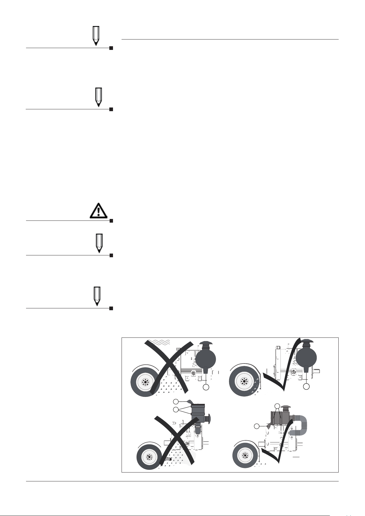
When selecting the machine mounting position, the following points should
be considered:
• Access to oil fill/level and drain plugs
• Adequate clearance to allow the cooling air to circulate around the
machine.
• Allow sufficient space for the installation of the Inlet and discharge lines,
including discharge silencer, if fitted.
• The machine should be protected from dust, flying stones and water
splashes.
• Install away from sources of heat, e.g. vehicle exhaust or hot pipes that
could effect the compressor temperature in any way.
• Venting relief/control valve air must be unobstructed and direct to the
atmosphere.
• Fit the relief and/or protection control valves as close as possible to the
SC200 discharge port.
• Venting valves must be positioned so that hot air cannot vent onto the
operator or the compressor
• Silencers should be fitted to the discharge port.
• Machine should be easily accessible for maintenance.
For the recommended layout of the machine and ancillaries see Pages 24 & 25.
Do not lift using other parts of
the machine.
CAUTION
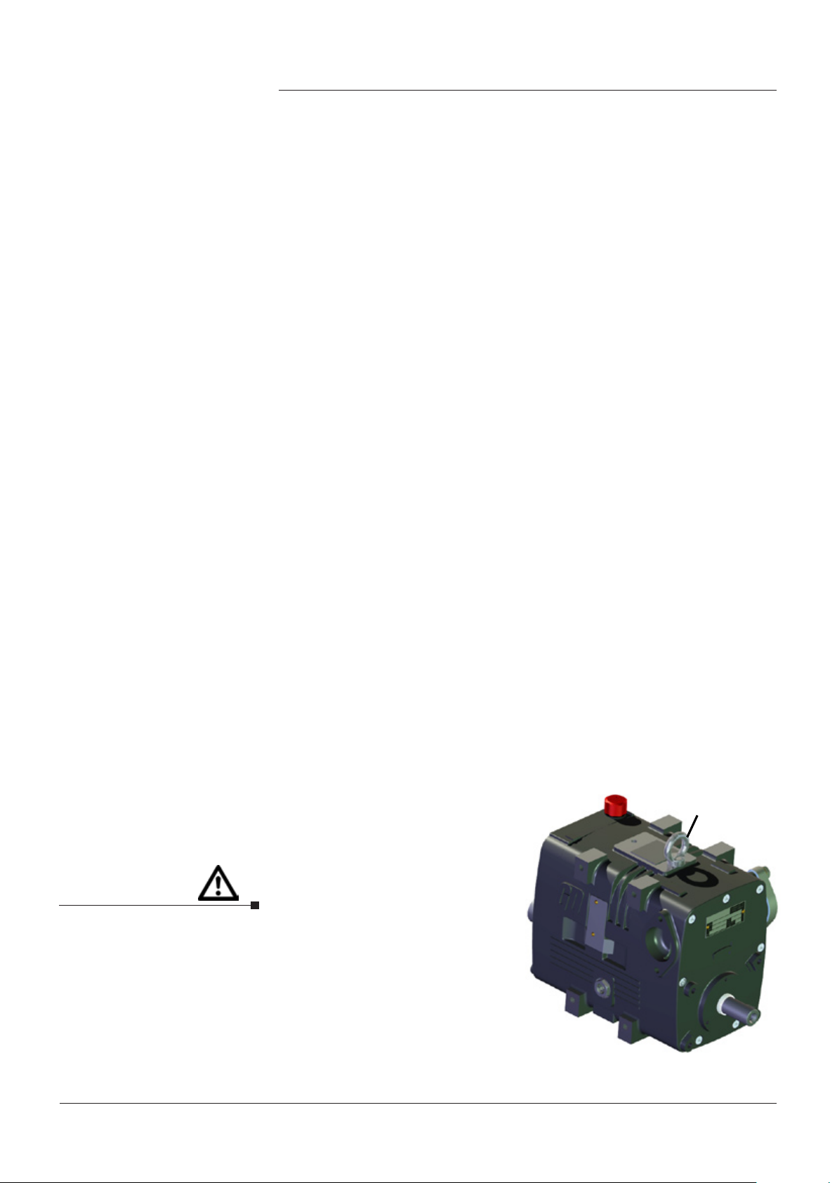
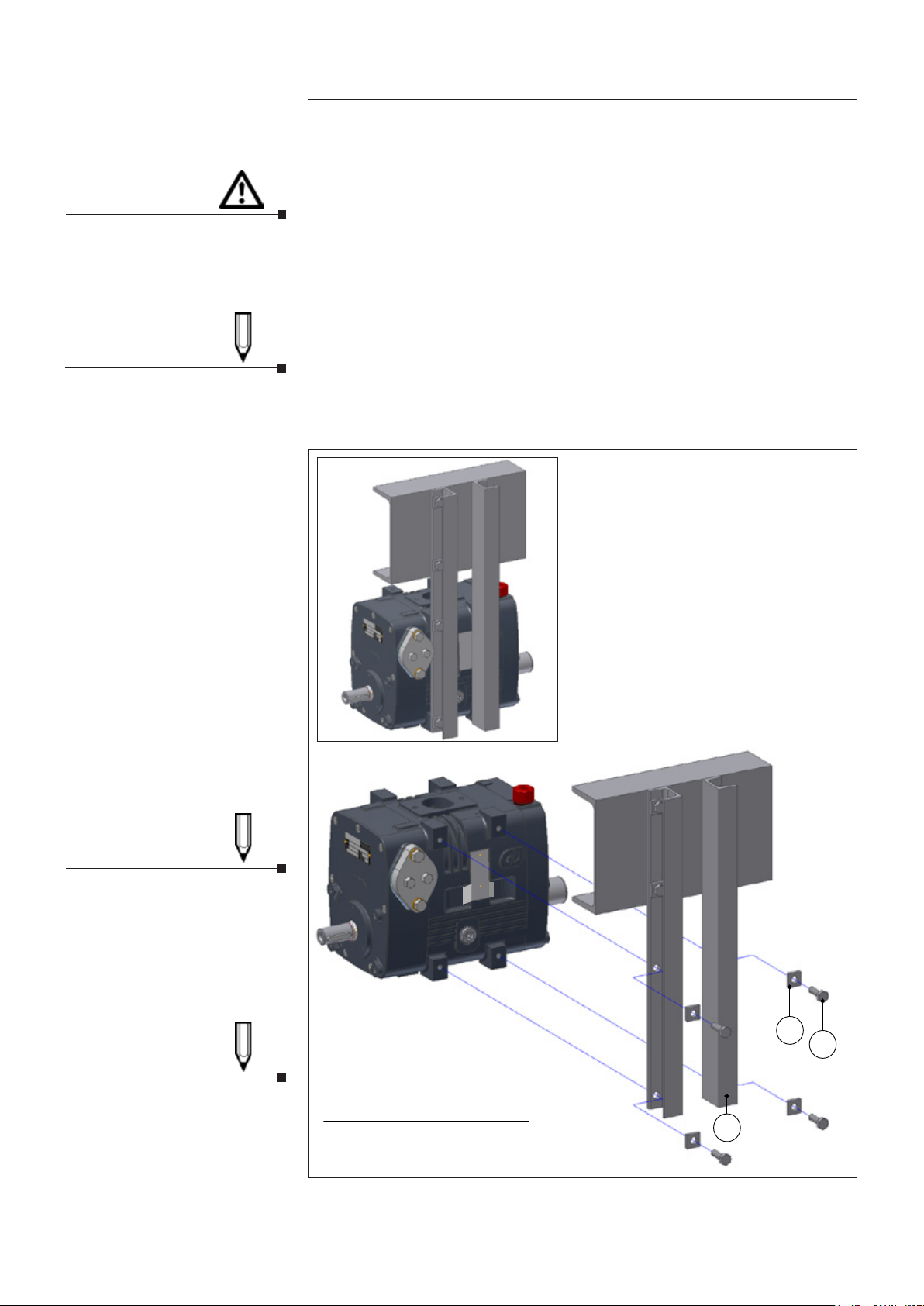
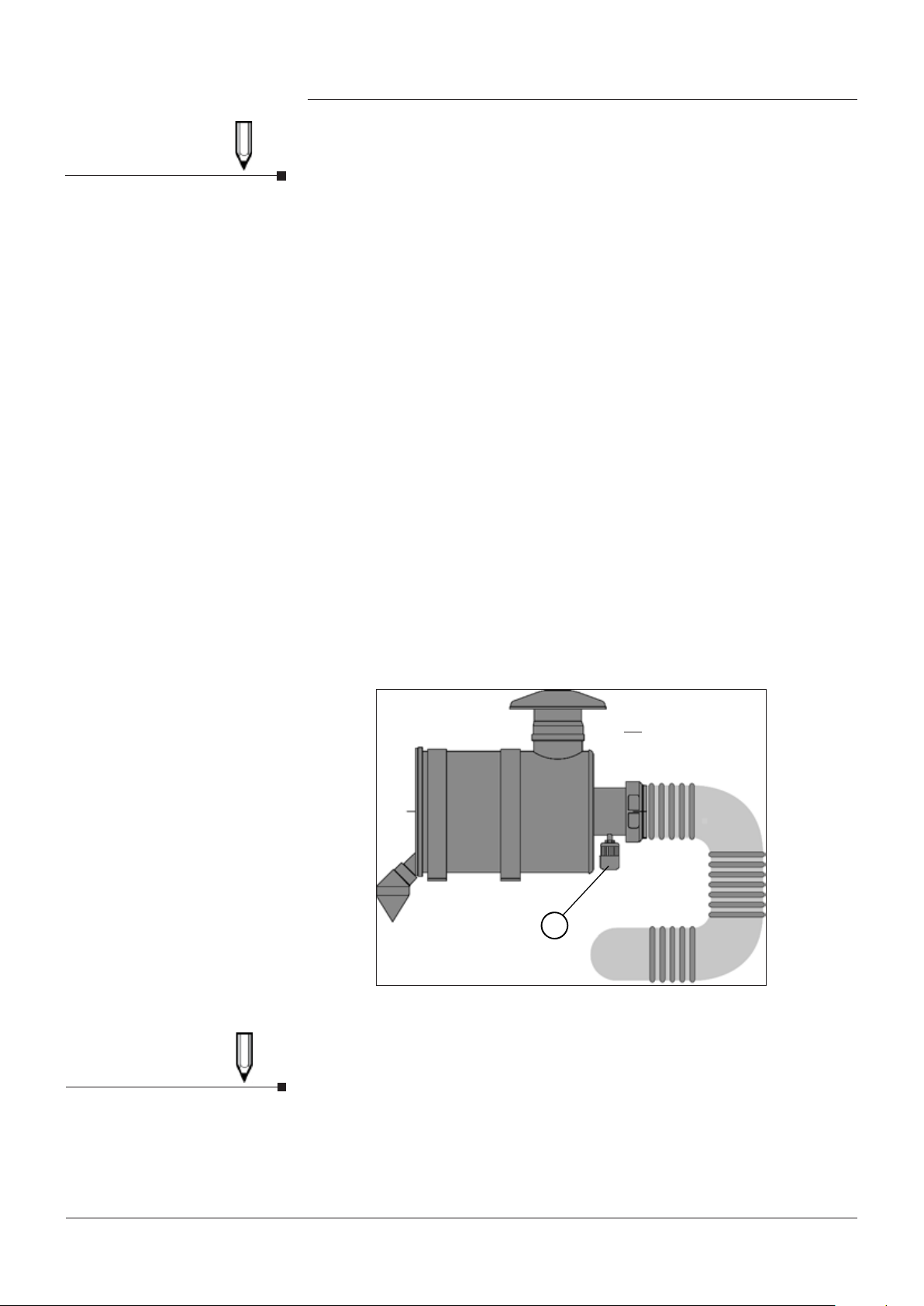
3.2 Lifting (see fig. 1)
• Avoid any use of force and load/
unload the packages with care.
• The weight of the basic compressor
without ancillaries is 42.5 kg.
• Remove all transport guards.
• Lift the machine using only the
securely mounted ring eye
bolt provided. (See Fig. 1/1).
• When the machine has been
installed, the supplied lifting eye
bolt should be removed and the
cover holes fitted with blanking
grommets.
• Any equipment used for lifting
should be rated accordingly. Figure 1. Lifting Eye Bolt

Page 74990395005 Date:02/11 SC200 Installation, Operating & Maintenance Manual
Installation
3.3 Mounting (see fig.s 2a & 2b)
• The compressor must be mounted with the discharge port up
(in the ‘Z’ direction as shown in Fig 2a).
• The drive shaft should be horizontal. (Engine or Hydraulic drive).
• The permitted deviation from the horizontal line should not exceed ±10°.
(Prop. shaft drive).
• The machine is secured at all four points on one of three sides using four
screws (see Fig. 2a/1).
• The mounting face to which the basic machine is fitted should be flat to
avoid distortion/stress.
• The mounting bolts/locking nuts should be:
Fastening Screws
Size M10
Strength Class 8.8
Tightening Torque 45 Nm
Installation Depth 15mm - 18mm
Surface Protection Recommended
Damage to the machine
When installing the machine,
ensure that it is level and not
rotated around the ‘X’ or ‘Y’
axis.
CAUTION
Figure 2a. Attachment Points
z
y
x
Key
1 - Attachment Points
2 - Vent Cover

Page 84990395005 Date:02/11 SC200 Installation, Operating & Maintenance Manual
Installation
3.3 Mounting (Cont..)
• The machine should be mounted to the truck frame using mounting
channels (Fig. 2b/1). Alternatively a specially made bracket can be
manufactured to support the compressor.
• The machine has three sets of mounting holes (Fig. 2a/1) located on the
right, left or bottom of the casing and these are provided to maximise
the mounting options available to the installer.
• Spacers may be required if the machine is fitted with a discharge silencer.
See page 23 for dimensions of an SC200 with silencer fitted.
• If a mounting bracket is used, this must be suitable to support the weight
of the compressor and operating loads.
• The fastening points should be in one plane (Fig. 2b/1).
Damage to the machine
When installing the machine,
ensure that it is level and not
rotated around the ‘X’ or ‘Y’
axis.
CAUTION
The taper washers should
be replaced by flat washers
if mounting channels with
parallel flanges are to be used.
NOTE
Figure 2. Attachment Points
1
23
Item Qty Description
1 2 Mounting Channels
2 4 M10 - Taper Washers
3 4 M10 - Hex. Head Screws
It may be necessary to
use alternative mounting
channels due to other vehicle
ancillaries (e.g. fuel tank).
These channels should be of
a comparable strength to the
configuration shown.
NOTE
For weights and dimensions
see Section 2.3, Page 5,
“Machine Specification Data”.
NOTE
Figure 2b. Mounting Details

Page 94990395005 Date:02/11 SC200 Installation, Operating & Maintenance Manual
3.4 Pipework
3.4.1 Discharge Line
•
Consider the weight and thermal expansion of the discharge pipe.
Connect the downstream discharge piping to the flange of the discharge
silencer without stressing it.
• A condensate trap should be installed at the lowest point of the pipeline.
• Pipework that is corrosion-resistant inside is recommended.
• Pipework should be attached to the vehicle chassis using flexible
mountings to prevent unnecessary vibration and noise transfer.
• A flexible element is recommended in the discharge pipework to prevent
distortion of the machine from the fabricated pipework through chassis
movement and heat expansion.
3.4.3 Inlet Line
• An inlet kit is supplied with the SC200 compressor assembly.
• A flexible inlet pipe is provided as part of the inlet kit, which is shown in
more detail on pages 24 & 25.
• To maintain the integrity of the compressor air supply, the inlet kit must be
used on all SC200 installations.
Non compliance could result in machine failure.
3.4.4 Inlet Air Filter
• A dry air filter with cyclone separator is provided. This filter is especially
suitable for Inlet air with a heavy dust load.
• The Inlet air filter should be supported separately and fastened using
the mounting bands provided (Fig. 3d).
• Install the Inlet air filter in a horizontal position (Fig. 3c or 3d). The dust
discharge valve of the Inlet air filter should point down (Fig. 3c & Fig 3d).
• The Inlet air filter should be located away from likely sources of dust,
flying stones, water splashes, waste heat and the diesel engine exhausts
(Fig 3a and Fig 3b).
Installation
Install Inlet Filter
NOTE
Key
1 - Mounting Bands
2 - Dust Discharge Valve
Important for Installation:
Flow direction, space for
changing the filter insert, no
leaks in the inlet line of the
machine.
NOTE
Figure 3. Installation of the Inlet Air Filter
All lines must be sufficiently
large. If inlet pipes of the
wrong diameter are used, it
may invalidate the warranty.
NOTE
Damage to the Machine
CAUTION
The minimum ID of the
discharge line is 50mm
NOTE
a)
2
2
b) 1
2
1
d)
c)
2

Page 104990395005 Date:02/11 SC200 Installation, Operating & Maintenance Manual
Installation
3.5 Ancillaries
The safe operation of the machine, i.e., operation without safety risk,
requires the following safety and monitoring devices:
Inlet Side
• Inlet air filter with maintenance indicator
Discharge Side
• Non-return valve
• Pressure gauge
• Pressure relief valve
Guards
• Protects from rotating parts and risk of burns
Protection of the Machine
• Speed monitor
3.5.1 Inlet Air Filter
For function and installation, see section 3.4.4, page 9.
Maintenance Indicator of the Inlet Air Filter
The visual maintenance indicator on the Inlet air filter of the compressor
(Fig. 4/1) indicates the state of the filter element in the Inlet air filter.
The maintenance indicator should be easy to see after installation.
Failure to follow the safety
instructions will invalidate the
warranty
NOTE
1
3.5.2 Pressure Gauge
• It is recommended that a pressure gauge be fitted directly after the
discharge port of the machine to provide constant information on the
compressed air pressure.
Figure 4. Maintenance Indicator on the Inlet Air Filter
Key
1 - Maintenance Indicator
The Pressure gauge should
have a range of 0 to 2.5 Barg
NOTE

Page 114990395005 Date:02/11 SC200 Installation, Operating & Maintenance Manual
Installation
3.5.3 Pressure relief Valve
• The relief valve is installed to prevent the SC200 from encountering
pressures beyond it’s operating range.
•
The relief valve should be installed as close as possible to the discharge port
of the machine either in the reactive silencer (see page 25) or prior to any other
discharge ancillary (See page 24).
• The relief valve is preset, wired and leaded (tamper proof) and fitted
to protect the SC200 (rather than the system which should be protected
by the vehicle tank relief valve) against pressures of over 2.5 barg.
Adjustment of the machine relief valve will invalidate the warranty of the
SC200 and the relief valve.
The relief valve required to protect the machine is a custom component set
to gardner Denver specifications. This valve is only available from Gardner
Denver and use of any other valve may invalidate warranty.
When mounting the pressure relief valve observe the following:
• Mount the valve as shown on pages 24 and 25.
• Make sure that the component markings and the safety seal are present.
• The valve must not be blocked.
• Do not use the pressure relief valve to regulate the compressed air
delivery.
3.5.4 Noise Control
Discharge Silencer (Reactive)
• The discharge Silencer reduces the high-frequency vibrations/noise
in the discharge line system.
• Ensure that the piping installation does not stress the flange.
3.5.5 Guard
• The machine, drive and all hot discharge lines must be fitted with guards
or suitable warning labels. The design of the machine must make it
impossible to touch any rotating or reciprocating parts of the machine.
3.6 Cooling
• The housing of the SC200 screw compressor is cooled by the ambient air.
Damage to the Flange at the
outlet of the discharge silencer
CAUTION
Risk from Moving Machine Parts
WARNING
Damage caused by incorrect
adjustment is not covered
under warranty.
NOTE
NOTE

Page 124990395005 Date:02/11 SC200 Installation, Operating & Maintenance Manual
3.7 Drive
• The rotor shaft should not be exposed to the axial thrust of the drive.
• Do not fit drive components onto the rotorshaft with a hammer.
• If the compressor is powered by a combustion engine, the engine must
have speed control which ensures that the compressor cannot run at
higher than the permitted maximum speed if the load drops.
• Install a coupling guard complying with safety instructions.
• Please note the step-up or step-down ratio of the transmission (truck p.t.o.,
large gear assembly, small gear assembly, etc.).
• It is recommended that speed control at the machine is provided with
indication at the place of operation.
• Check the speed after setting up the compressor and fix up a notice for
the truck driver.
3.7.1 Drive by Hydraulic Motor
• The compressor side half coupling is supplied loose.
• Suitable coupling flanges can be supplied on request.
3.7.2 PTO and Prop. Shaft Drive Alignment
Shaft Cover
• The compressor can be driven from either end of the input shaft
(see section 3.3 for possible mounting arrangements).
• The clockwise end of the compressor input shaft is protected with a
shaft cover. If this shaft is required, remove the cover and refit it over
the unused shaft at the opposite end of the machine.
Drive couplings
• Before fitting the drive coupling, ensure the machine shaft and drive
coupling are clean and damage free to help ensure the flange fits correctly.
• Both the shaft and the coupling bore should be smeared with a light oil to
aid future separation.
• A Hollow Set Screw (Grub Screw) should be used for retaining the drive
flange in position on the shaft.
• Apply Loctite 270 to the Grub Screw and tighten to a torque of 7Nm.
• Flange/coupling removal should only be undertaken with the aid of a
puller type device with a screw in the shaft end (see Fig. 5a) to avoid
damaging the flange or shaft end.
Installation
Damage to the Machine
CAUTION
For Permitted Speeds See
Section 2.3, Page 5.
NOTE
Figure 5a. Drive Flange Removal

Page 134990395005 Date:02/11 SC200 Installation, Operating & Maintenance Manual
3.7 Drive (Cont..)
3.7.2 PTO and Prop. Shaft Drive Alignment (Cont..)
Alignment (See Fig. 5b)
• The axis of the majority of PTO’s are mounted at approximately 2° - 5°
to the horizontal, which reflects the angle of the engine and gearbox.
• The compressor should be mounted so that its drive axis is parallel to
the PTO’s drive axis.
• The compressor should also be mounted so that the prop. shaft angle
between the PTO and SC200 in any plane is less than or equal to 12°.
• Consideration should be given to the prop. shaft length when mounting
the machine.
• The prop. shaft should be sized so that it always has sliding clearance.
• In addition it is also important to ensure the propshaft is not installed
fully extended.
Figure 5b. Drive Alignment
Installation
The compound prop. shaft
angle must also be less than 12°
NOTE
Also check the prop. shaft
manufacturers information
NOTE
These Two Angles To Be Equal

Page 144990395005 Date:02/11 SC200 Installation, Operating & Maintenance Manual
4.1 Start-Up
4.1.1 Checking The System
The first start-up and also the start-up of the compressor after an extended
period of shutdown (over 4 weeks) is critical to the optimal function of the
compressor.
Prior to Start-up proceed as follows:
• Inspect the compressor for any damage and ensure all flanges, fasteners
and mountings are secure.
• Ensure the machine, drive and all hot discharge lines are fitted with guards
or suitable warning labels.
• Ensure all operators have read and understood the operating procedures.
• The machine shaft should not lock when turned.
• All pipework bores should be clean and free of debris.
• If the compressor is prop. shaft driven, ensure the vehicle PTO is
disengaged and the engine management system is setup correctly for the
application
• All ancillaries are correctly fitted and sequenced.
• Blow (ball) valve open (if starting against a tank pressure).
• Commissioning gate valve and silencer fitted.
4.1.2 Oil Fill
• Check Lubrication plugs are fitted.
• Fill the machine with sufficient oil, as specified in the lubricating
recommendation of the compressor.
4.1.3 Checking The Direction Of Rotation
• The machine should rotate in the direction of the arrow on the casing.
The compressor has a drive shaft on either end ensuring a machine that
can run either clockwise or anti-clockwise is always available.
• Ensure the drive is engaged gently when starting.
• Briefly turn on the drive to ensure the correct rotation.
4.1.4 Shut-Off And Other Valves
• Inspect the non-return valve mounted in the discharge line for correct
direction (arrow on valve housing).
• Open all manual shutoff and other valves. The shutoff valves in the
discharge line should not be closed. Closed valves can cause the
compressor to fail.
• Check the function of the relief valve by operating the manual
venting function while the compressor is running.
• Do not use the compressor as vacuum pump.
• Use suitable protective equipment.
4.1.5 Turn On, Check Speed & Compression Discharge Pressure
• Turn on the drive and observe the pressure build up in the compressor.
Speed
• For the permitted operating speed range see section 2.3, page 5.
Operation & Commissioning
4
Do not skip any steps.
Proceed slowly and with
care. Any damage caused by
incorrect start-up will not be
covered by the warranty.
NOTE
For oil filling instructions and
recommended lubricants, see
section 5.4, Page 18.
NOTE
Risk of burns due to hot
compressed air
WARNING
Damage to the Machine
CAUTION
The shaft cap should be fitted
to the non-drive end of the
compressor.
NOTE
Damage to the Machine
CAUTION

Page 154990395005 Date:02/11 SC200 Installation, Operating & Maintenance Manual
4.1 Start-Up (Cont..)
Discharge Pressure
• For the operating pressure range see section 2.3, page 5.
• Check to ensure the relief valve opens at 2.5barg ±10% gauge pressure
and blows off any excess pressure.
• Improper setup or installation of the compressor, or manipulation of the
relief valve can cause a pressure and temperature rise with risk of
machine failure.
4.2 Operation
• The compressor should be started in line with Section 4.1, Page 14.
4.2.1 Inspection During Operation
• The compressor should be inspected regularly during operation.
• Check the working gauge pressure regularly as described in Section 2.3, Page 5.
• Check the operating speed regularly as described in Section 2.3, Page 5.
• Control of the intake temperature is optional.
4.2.2 Relief Valve Inspection
• The setting of the relief valve must be protected against unauthorized
and/or accidental change.
• The relief valve must not be blocked or tampered with.
• Check the function of the relief valve by operating the manual venting
function while the compressor is running once every week.
• Always use suitable personal protection equipment.
The valve must be set to the maximum permitted operating pressure (see
section 2.3, page 5).
• The relief valve should never be used for controlling pressure.
4.2.3 Maintenance Indicator
• See Section 3.5.1, Page 10, & Section 5.5, Page 19 for details of the
maintenance indicator.
4.2.4 Air Filter Element
• See Section 5.5, Page 19, for instructions on changing the filter element.
4.2.5 Maximum Incline During Operation
• The maximum permitted inclined position along the compressor
longitudinal and transversal axes should not exceed 10° from
the horizontal line. Observe the truck position.
• Inclining the compressor position more than 10° will damage the machine.
4.2.6 Oil Level inspection
• Check the oil level in the compressor at the sight glass every week.
•
Operation & Commissioning
4
Damage caused by incorrect
start-up is not covered under
warranty.
NOTE
Damage To Safety Equipment
WARNING
Risk of Burns Due To Hot
Compressed Air
WARNING
Damage To The relief Valve
CAUTION
Damage To The Machine
CAUTION

Page 164990395005 Date:02/11 SC200 Installation, Operating & Maintenance Manual
4.3 Inspection Intervals
Damage to the Machine
CAUTION
Damage to the Machine
CAUTION
Operation & Commissioning
4.4 Extended Shutdown
• The compressor should be cleaned thoroughly if it is to be shut down for
an extended period of time
• If high pressure water jets are used, water can enter the compressor and
cause extensive damage leading to compressor failure.
• Run the machine warm for several minutes after wet cleaning to avoid
corrosion due to moisture.
• If the compressor is truck mounted and is used infrequently, we
recommend running the compressor for at least 15 minutes once every
week to maintain the compressor and pipework in good condition.
Value
Every 10-20
Min When
Running
After
Every Use Daily Weekly See
Section
Operating Speed 1,200 to
1,800 min-1
2.3
Working Gauge Pressure 2.0 Bar
2.3
Check Safety Valve
4.2.2
Inspect/Clean Machine
5.3
Oil Level
4.2.6
Air Filter Maintenance
Indicator
5.5
Note: Condensed water can accumulate in discharge pipework and should be removed regularly.

Page 174990395005 Date:02/11 SC200 Installation, Operating & Maintenance Manual
Maintenance
55.1 Warranty
• Damage caused by non-compliance with these operating instructions are
not covered by the warranty.
• Compressor repairs should be carried out by an authorized repair centre
using original parts; otherwise the warranty will be invalid.
5.2 Maintenance Schedule
• The compressor must be maintained by trained personnel.
• The machine must not be running and the pressure in all lines must be
relieved.
• Failure or interruption of operation due to poor or improper maintenance
can result in very high repair costs and increased machine downtime.
Regular authorized maintenance is therefore a ‘must’.
• The maintenance intervals in the table below refer to intermittent
operation. As service conditions vary, exact time intervals for
maintenance, preventive repair and inspections cannot be specified.
The table is only for guidance.
Observe Safety Instructions
in Section 1, Page 3 for all
maintenance & Inspection work
CAUTION
Install all guards properly at
the end of any work
NOTE
5.3 Cleaning
• If high pressures jets are used when cleaning, water can enter the
compressor and cause extensive damage leading to machine failure.
• Run the machine warm for several minutes after wet cleaning to avoid
corrosion due to moisture.
Damage to the Machine
CAUTION
The Compressor should be
cleaned every week
NOTE
Maintenance
locations Activity See
Chapter
Maintenance Intervals
Weekly Monthly Quarterly Yearly
Compressor Clean 2.3
Air Filter Inspect/Change 2.3
Safety Valve Inspect/Actuate 4.2.2
Non-Return Valve Check 5.3
Oil Level Inspect/Add Oil 4.2.6
Oil Change Change 5.5
or 500 h

Page 184990395005 Date:02/11 SC200 Installation, Operating & Maintenance Manual
Maintenance
5.4 Oil Change
Change the oil regularly after the specified interval.
Lubricant to be Mobil Delvac MX 15/W40 or better oil which must meet
or exceed the specification API CI-4 as a minimum.
Temp. Range: -10°C to +35°C.
Volume: 1.2 Litres approx.
Remove the oil drain plugs. (Fig. 6/1).
Collect the spent oil in a suitable container.
lnstall the oil drain plugs.
Remove the oil filling plug (Fig. 6/2) and fill with approx. 1.2 litres of new oil.
Stop filling when the level reaches the top edge of the oil sight glass (Fig. 6/3).
•
•
•
•
•
•
•
Dispose of all oil, grease,
cleaner or components
such as filter elements,
as prescribed by the local
environmental laws.
NOTE
Figure 6. Oil Change
Key
1 - Oil Drain Plug
2 - Oil Filling Plug
3 - Oil Sight Glass
OPTION B

Page 194990395005 Date:02/11 SC200 Installation, Operating & Maintenance Manual
The filter element should
be changed when the
maintenance indicator shows
red (Fig. 7a/1).
NOTE
Maintenance
5.5 Inlet Air Filter
The maintenance indicator indicates the state of the filter element in the
Inlet air filter. The filter element should be replaced/cleaned when the
Maintenance indicator enters the red portion of the blockage scale (Fig. 7a/1)
If the indicator valve has entered the red portion of the scale:
• Press the reset button and re-check with the compressor operating.
• If the blockage indicator still returns to red, the filter must be either
cleaned or replaced.
Cleaning the Casing
• Unclip the clamp retaining the end cover (Fig. 7b/1) of the air filter and
remove it noting the position of the vacuator valve (Fig. 7b/5).
• Empty out any dust or dirt and then re-fit in the original position (vacuator
valve downwards).
Cleaning/Replacing the Element
• Remove the end cover by releasing the retaining clips and withdraw
the filter (Fig. 7b/1).
• Clean the filter by blowing compressed air through the filter from the
inside outwards or replace with a new filter element (Fig. 7b/2).
• Clean the inside of the filter body and end cover by blowing with
compressed air.
• Replacement of the element/end cover is a direct reversal of the above.
• After cleaning the filter, push the hook-shaped pressure switch of the
maintenance indicator inward (the colour changes from red to colourless)
• The maintenance indicator is again ready for service (Fig. 7a/2).
Make a weekly check of
the vacuator valve by
compressing the valve to
note any dust collection.
NOTE
Stop the machine before
cleaning or replacing the
filter elements
NOTE
Key
1 - End Cover
2 - Filter Element
3 - Raincap
4 - Maintenance Indicator
5 - Vacuator Valve
Figure 7b. Inlet Air Filter
Figure 7a. Maintenance Indicator
Key
1 - Filter Blocked
2 - Filter Clear

Page 204990395005 Date:02/11 SC200 Installation, Operating & Maintenance Manual
Maintenance
5.6 Troubleshooting
5.6.1 Possible Operating Errors
Operating errors can cause failure of the machine. Conditions to avoid are:
• Speed lower or higher than the permitted limit.
• Very quick start-up.
• Too high discharge pressure (gauge pressure)
• Start-up against pressurized system.
• Blow-off of air flow by the pressure relief valve when the discharge line is closed.
• Excessive discharge temperature.
• Soiled Inlet air filter.
• Blocked silencer.
• Blocked pipe.
• Intake of liquid.
5.6.2 Remedial Action
• If a problem occurs, refer to the table below for possible causes and
remedies.
• If a problem occurs which is not described in the table, contact our
customer service personnel.
• If a problem persists, please contact our customer service personnel.
Failure due to operating error
is not covered by the warranty
CAUTION
Possible
Cause Remedy
Poor Output
Air Inlet Filter Blocked
Input Speed Too Low
Clean intake air filter, replace cartridge if necessary
Keep within permitted speed range
Abnormal Sound
Compressor tilt too large
Bearing defective
Wrong speed
Pressure fluctuations
Air Leak on Discharge line
Keep within max. tilt of 10°
Inform customer service
Keep within permitted speed range
Keep within permitted working gauge pressure
Locate Leak and Fix
Compressor Does Not Deliver Operating Gauge Pressure
Incorrect Pressure gauge reading
System leak
Replace pressure gauge
Repair leak
Compressed Air Temperature Too High
Discharge pressure too high
Line blocked
Intake air filter blocked
Input Speed Too low
Keep within permitted working gauge pressure
Remove blockage
Clean intake air filter
Keep within permitted speed range
Power Consumption Too High
High speed
High discharge pressure
Pressure gauge showing wrong reading
Keep within permitted speed range
Keep within maximum permitted operating pressure
Replace pressure gauge
Safety Valve Blows Off Air
Shutoff valve in discharge line is closed
Discharge pipework is blocked
Open the shutoff valve.
Unblock Discharge Pipework
Table of contents
Popular Air Compressor manuals by other brands

PROPOINT
PROPOINT Twin Tank Wheelbarrow user manual

T L Audio
T L Audio CRIMSON C-3021 user manual

ALLPOWER
ALLPOWER APC4025 owner's manual

Bushpower
Bushpower WM102-7C operating instructions

CO/Tech
CO/Tech VZB-0.14/8-VFL-50 Original instructions

BOSSCO
BOSSCO 36 BHP PISTON Service and maintenance user manual