DSI DST-80 User manual

Service & Installation Manual
Note: Successful turnstile installation depends on reading this manual.
Please keep this service manual after installation. If an installation is done by a construction company
or outside installer, please pass this book along to the end user. This book is required for maintenance,
troubleshooting & repairs.
512-321-4426
INS-DST80S-190401
Designed Security, Inc - 1402 Hawthorne Street, Bastrop Texas 78602 - (800) 272-3555
DST-80
Single Full Height Turnstile

Important Electrical Information
Installation of the control head mechanism into the turnstile requires a grounding-type outlet recep-
tacle installed inside of the frame or cabinet through the provided conduit access points.
To reduce the risk of electric shock, this equipment has a grounding type plug that has a third
Additionally, the P24-60W power supply from this appliance must be grounded to the frame of the
turnstile. Utilize the green colored grounding screw threaded into the grounding tab located near the
power supply along with the provided grounding wire from the power supply to ensure the equip-
ment is properly grounded.
Do not connect to a receptacle controlled by a switch.
Feature Level
Destructive Attack Test I
Line Security I
Endurance IV
Standby Power I
ULC S319, Class 1
Wiring methods shall be in accordance with:
National Electrical Code, ANSI/NFPA 70
Canadian Electrical Code, CSA C22.1, Part I, Safety Standard for Electrical Installations
When in an appropriate turnstile or gate model, the 6500 Series Control Head is suitable for indoor
and outdoor use.
512-321-4426
INS-DST80S-190401
Designed Security, Inc - 1402 Hawthorne Street, Bastrop Texas 78602 - (800) 272-3555

Table of Contents
Important Electrical Information 2
DST80 Parts List 4
DST80 Fastener List 5
Installation Instructions 6
Mechanical Overview 7
Internal Parts Breakdown 8
Parts List 9
10
Locking Bar Information 11
Hydraulic Shock & Indexing 13
Electrical Introduction 14
Wiring Diagram 15
Wiring Legend 16
Limit Switch & Limit Switch Cam Information 17
Logic Controller Settings 18
Testing Procedure 19
Maintenance & Cleaning 20
Troubleshooting 21
Proper Turnstile Usage 24
Warranty 25
Appendix
512-321-4426
INS-DST80S-190401
Designed Security, Inc - 1402 Hawthorne Street, Bastrop Texas 78602 - (800) 272-3555

DST80 Parts List
1.) 1x Mainframe Assembly
2.) 1x Rotor Assembly
3.) 1x Barrier Assembly
4.) 2x Curved Yoke Assemblies
5.) 1x Control Head Assembly
6.) 1x Fastener Kit
512-321-4426
INS-DST80S-190401
Designed Security, Inc - 1402 Hawthorne Street, Bastrop Texas 78602 - (800) 272-3555

DST80 Fastener List
Qty 2 - ¾” x 90” Hollow Threaded Rod (for card reader conduit)
Qty 3 - ¾” x 90” Solid Threaded Rod
Qty 5 - ¾” Nuts
Qty 1 - PVC Bearing Block
Qty 3 - 3/8” x 5” Flathead Shield Anchors
Qty 1 - Bearing Assembly w/ Hex Sha& Washer
Qty 1 - 10/24 Buon Head Cap Screw* (Barrier to Main Frame)
Qty 4 - 3/8” x 1 ½” Bolts w/ Nuts, Washers & Lock Washers*
(Control Head to Main Frame)
Qty 1 - Liquid Grout Packet
*Located inside of the main frame
512-321-4426
INS-DST80S-190401
Designed Security, Inc - 1402 Hawthorne Street, Bastrop Texas 78602 - (800) 272-3555

DST80S Installation Instructions
1.)
Floor should be level +/- 1/8”. If the floor is not level, the turnsle will need to be
shimmed.
2.)
Use the cross arm and main channel assembly as a template to mark the 5x anchor holes
onto concrete.
3.)
Drill the 5x 7/8” holes for the curved yokes and staonary barrier 4” deep, clean holes of
debris.
4.)
Insert rods into yokes and barrier. The hollow rods (to be used as wire races) should be on the
card reader mounng side of the yoke assemblies. The solid rods belong to the inner posts of
the yoke assemblies and the staonary barrier.
5.)
Erect frame of turnsle by standing curved yoke assemblies and staonary barrier upright and
insert the rods into the drilled holes in the concrete.
6.)
Rest the mainframe ontop of the curved yoke assemblies and staonary barrier, fing the rods
through the holes provided. Do NOT install nuts for the rods yet.
7.)
Block the yoke assemblies and barrier up to provide space underneath and pour epoxy grout
into each of the 5 holes. Allow epoxy to cure before removing blocks.
8.)
Once the epoxy has cured, remove the blocks from under the curved yokes and staonary
barrier. Thread the 3/4"-10 nuts onto the threaded rods to secure frame to concrete. Shim
where necessary to ensure mainframe is level +/- 1/8”.
9.)
Using a plumb-bob, mark the rotor’s bearing locaon on the concrete.
10.)
Set the PVC bearing cup so that the bearing aligns to the center of the plumb-bob and drill 3x
3/8” holes. Secure bearing block assembly to concrete with provided 3/8” anchors.
11.)
Place the bearing with 7/8” hex insert onto bearing cup and install rotor onto bearing
assembly.
12.)
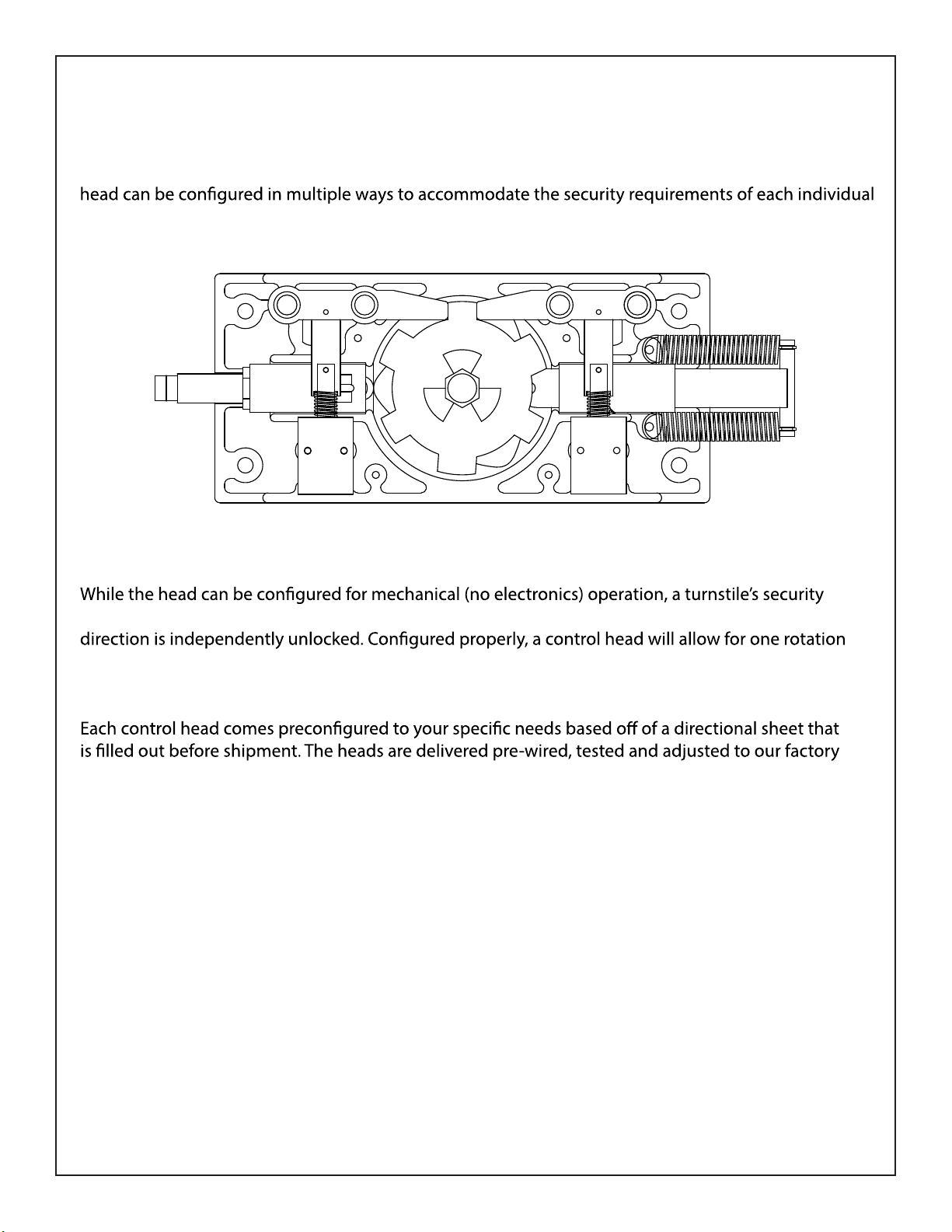
Install control head into the rotor and mainframe. Ensure that the alignment on the rotor is so
there is one set of arms in between the two curved yoke assemblies (see diagram below).
13.)
Refer to control head informaon in the remainder of the book for electrical informaon,
troubleshoong, and other informaon about operaon of the turnsle.
512-321-4426
INS-DST80S-190401
Designed Security, Inc - 1402 Hawthorne Street, Bastrop Texas 78602 - (800) 272-3555

6500 Series Control Head Mechanical Information
All of our turnstiles and ADA gates operate with a mechanism called the 6500 Series Control Head.
This sturdy and easy to maintain drive for the turnstile has replaced all previous model control heads.
It is adaptable to nearly any existing turnstile and comes with each new turnstile purchase. This control
job site.
An internal view of an electronically controlled two way 6500 series control head.
potential is reached in the case of an electronic two way control head. In this instance, each rotational
per valid entry request. Our anti-backup cams are designed so that it is mechanically impossible to
become trapped within the turnstile when properly installed.
recommendations. Installation is simple: connect inputs from access control devices into the logic
controller and plug the unit’s power supply into a 100-240 VAC (single phase) receptacle. The power
supply will automatically set itself to function on your local voltage and convert it to 24VDC.
512-321-4426
INS-DST80S-190401
Designed Security, Inc - 1402 Hawthorne Street, Bastrop Texas 78602 - (800) 272-3555

512-321-4426
INS-DST80S-190401
Designed Security, Inc - 1402 Hawthorne Street, Bastrop Texas 78602 - (800) 272-3555

Locking Bar Linkages
6519 - Fail Open
6518 - Fail Lock
Locking Bar Assemblies
0382 - Fail Open Assembly
0383 - Fail Lock Assembly
Limit Switch Cams
2267 - Standard
2268 - ADA
2269 - One-Way
Limit Switches
2180 - Standard
(Z-15GW2-B7-K)
1700 - One Way
(BZ2RW825-A2)
0372 - Top Casting
0373 - Bottom Casting
Control Head Castings
6532 - Index Pin
Proximity Sensor & Accessories
7211 - 24VDC PNP Prox. Sensor
w/ M12 Connector (Sick 1040763)
6589 - Turnstile Prox. Bracket
w/ 3x Mounts - LH, RH & Home
0766 - 3 Branch M12 Splitter
Cam Assemblies
0401 - 427/430/T80/WH (7/8 Hex)
0407 - 439/448/P60/HD (1.25" Hex)
0402-ADA (Must specify model)
Shock Housing Assemblies
6535 - WH/427/430/T80/ADA
6541 - 439/448/P60/HD
Control Head Bearings
Indexing Springs
1106 - Waist High (Light)
1108 - Full Height (Heavy)
1107 - ADA (Extra Heavy)
Solenoid Springs
6510 - Fail Open Spring
6016 - Fail Lock Spring
6051 - Solenoid
Deltrol D4A53717-82
Hydraulic Shock Absorbers
6560 - WH/427/430/T80/ADA
6561 - 439/448/P60/HD
0381 - Locking Bar Casting
w/ Oil Impregnated Bushings
6520 - Index Pin Tubing
+–
+–
L N
V Out
PS24-60W
0740 - Logic Controller (XD10)
1641 - 1” ID for HD Top Castings
&All Pre-2018 Tops (1641-2RSNR)
7208-Bottom Casting (6007RSNR)
1640 - 7/8” ID for Standard Duty
Top Castings (1640-2RSNR)
0750 - 24VDC Power Supply (60 W)
w/ NEMA 5-15 Drop Cord
I1
A B OKESC
I2 IB IC ID IE
+
+
–
–
01 02 03 04
XD10
512-321-4426
INS-DST80S-190401
Designed Security, Inc - 1402 Hawthorne Street, Bastrop Texas 78602 - (800) 272-3555

operating with the 6500 Series Control Head self-center with a spring driven indexing pin
and hydraulically shock to the home position to prevent damage or injury.
Manual both ways:
with an out of service lockout bar which would allow the end user to lock the turnstile with a
standard pad lock.
Manual one way: Turnstile rotates in one direction but not the other. This is often used for
egress only areas.
Electronic one way with free exit: Unit rotates freely in one direction but requires some
form of access control in the other. This is a typical installation in many facilities that want
Electronic one way with no exit: Turnstile is locked in both directions at all times, but in one
direction can be unlocked with access control. Typically, this would be installed in scenarios
where there is an alternate means of exiting the facility.
Electronic two way: Turnstile requires access control for both entering and exiting a facility.
Fail lock: Upon power failure, an electronically controlled direction would remain locked.
methods of exiting are available. Unless equipped with key overrides, this is can be easily
converted to fail open by ordering alternate parts. This is also known as fail secure.
Fail open: Upon power failure, an electronically controlled direction would remain open.
normal situations but in power outages it free wheels. Unless equipped with key overrides,
this can be easily converted to fail lock by ordering alternate parts. This is also known as fail
safe.
Key overrides: This option is available on either electronic or manual two way models. It
The key override option is not intended for constant every day use. Should you require an
additional lock-down feature on your turnstile, a better option (on a full height turnstile) is
an out of service lockout with a standard pad lock. Note that the key override option makes
available for some turnstile or gate models.
512-321-4426
INS-DST80S-190401
Designed Security, Inc - 1402 Hawthorne Street, Bastrop Texas 78602 - (800) 272-3555

6500 Series Control Head Locking Bar Information
The 6500 Series Control Head is built to order based on a direction set up sheet sent with
cabinet on the left for waist high.
“No passage” directions include a fail lock locking bar assembly as well as an unwired solenoid.
This adds the appropriate parts to the control head to prevent it from rotating in that direction.
“Free passage” (or manual) directions remove the solenoid and locking bar assembly, allowing
the cam to spin freely.
Each direction has a pair of holes on the locking bar and control head casting. These holes
act as pivot points for the locking bar casting. The inner holes are fail lock and outer holes
are fail open. A .5“ dowel pin slides through the entire assembly to hold everything in place.
Alternate linkages and springs are needed to convert a direction’s power failure status.
any key override equipped head to ensure everything is done correctly.
Direction 1 Solenoid
Direction 2 Solenoid
Fail Open
Pivot Point
Fail Lock
Pivot Point
Fail Lock
Pivot Point
Fail Open
Pivot Point
Fail Lock
Pivot Point
Fail Open
Pivot Point
0381
Locking Bar Casting
Hardened 4140 tool steel
casting w/ oil impregnated
bronze bushings.
512-321-4426
INS-DST80S-190401
Designed Security, Inc - 1402 Hawthorne Street, Bastrop Texas 78602 - (800) 272-3555

Extra components are required to do so.
Locking bar assemblies are held together with 1/8”spring pins. Extracting these pins and
Replacing an entire locking bar assembly is simple; punch the .5” dowel pin from the pivot
point through the head casting (via a small hole in the bottom casting for this purpose),
pull out the old locking bar assembly and replace it with the new one.
If changing from fail lock to fail open or vice versa, install the dowel pin in the alternate hole.
6500 Series Control Head Locking Bar Information (Continued)
6519
Fail Open Linkage
These have an approximate
length of 2.5” and do not
have the extra hole for the
key override option.
6510
Fail Open Solenoid Spring
These look similar to fail lock,
but are actually stronger in force.
Wire diameter is .041”.
6518
Fail Lock Linkage
These have an approximate
length of 2.25” and also
include an extra hole the
key override option.
6010
Fail Lock Solenoid Spring
These look the same as the fail open,
but are actually lighter in force
Wire diameter is .032”.
This spring was also used
on the 6100 Series Control Head.
0383
Fail Lock Locking Bar Assembly
Includes locking bar casting
w/ oil impregnated bushings,
solenoid spring, locking bar
linkage, and solenoid plunger.
0382
Fail Open Locking Bar Assembly
Includes locking bar casting
w/ oil impregnated bushings,
solenoid spring, locking bar
linkage, and solenoid plunger.
Locking Bar Linkage
Spring Alignment Tabs
Solenoid Spring
Correct Alignment Incorrect Alignment
Make sure the solenoid spring is between the alignment tabs on the linkage or the
assembly may bind when pivoting.
512-321-4426
INS-DST80S-190401
Designed Security, Inc - 1402 Hawthorne Street, Bastrop Texas 78602 - (800) 272-3555

6500 Series Control Head Hydraulic Shock Information
The 6500 Series Control Head utilizes a spring loaded index pin for auto-centering the cam
Set properly, the shock will allow a turnstile or gate to self-center while rotating smoothly
without slamming.
use a .75” diameter shock while larger full heights use a 1”diameter shock.
Hydraulic ShockIndex Pin
3/4” Hydraulic Shocks:
Setting:
Loosen the set screw on the head of the dial
and turn the knob. The dial can be set
between 0 and 8. The higher the number, the
stronger the shock is. Tightening the set screw
can alter the shock strength so a good habit is
to loosen the set screw, turn the dial, tighten
the set screw then test your setting. Repeat
Replacement:
Thread the new shock into the shock housing
as far as it will turn while the cam is in the
home position. Once it bottoms out, thread
the shock back out 1.5 - 2 turns until the
numbers on the dial are facing upright. Some
models may require an additional turn or two
outward if the arm does not self center on
even the lowest setting.
1” Hydraulic Shocks:
Setting:
Loosen the set screw on the head of the dial
and turn the knob. The dial can be set
between 0 and 8. The higher the number, the
stronger the shock is. Tightening the set screw
can alter the shock strength so a good habit is
to loosen the set screw, turn the dial, tighten
the set screw then test your setting. Repeat
Replacement:
Thread the new shock into the housing as far
as it will turn while the cam is in the home
position. Once it bottoms out, thread the
shock back out 1.5-2 turns until the set screw
pointer is facing upright. Fasten the shock into
the housing by snugging the 1/4-28 set screw
into the bronze housing (snugly, but do not
over tighten or the brass might start to tear).
Failure to turn the shock back out after threading it in all of the way will likely cause the part
to wear out very quickly.
512-321-4426
INS-DST80S-190401
Designed Security, Inc - 1402 Hawthorne Street, Bastrop Texas 78602 - (800) 272-3555

6500 Series Control Head Electrical Information
Each electronic control head comes with a power supply, a programmable logic controller (PLC), limit
switches (or optionally, proximity sensors) and solenoids. For safety purposes, it is recommended that
you read all literature on the electrical components before attempting to install the control head into
a turnstile.
The 6500 Series Control Head is on the third generation of electronic components. The new XD10 logic
controller is a direct replacement of both the 0789 control board and 6789 (Keyence KV-16DR) logic
controller.
The latest enhancements provide a broader temperature range for outdoor installations (-4 to 131F)
as well as a user friendly text based interface with a daylight visible display. With this also comes
some new features such as on board testing buttons, turnstile statistics / information, etc.
with installed products. If an installation has the old 0789 circuit board (PCB) and has the optional
proximity sensor upgrade, new proximity sensors will need to be purchased. This is because the
0789 board had NPN inputs while the XD10 (and the KV-16DR) have PNP inputs.
The new PLC still requires relay contact closures for inputs just like all previous generations, so any
installation is compatible in one way or another. If assistance is needed with understanding how
to convert the wiring from access control to the new logic controller, please view this manual or
call our technical support department for assistance.
I1
A B OKESC
I2 IB IC ID IE
+
+
–
–
01 02 03 04
XD10
Inputs
To activate, apply local 24VDC + to desired input terminal.
Full Height Models:
Dir 1 - Clockwise
Dir 2 - Counter Clockwise
+
24
VDC
-
24
VDC
I1
Dir 1
Input
I2
Dir 2
Input
IB
Dir 1
OR
IC
Dir 2
OR
ID
Dir 1
Limit
IE
Dir 2
Limit Waist High Models:
Dir 1 - Right Hand
Dir 2 - Left Hand
Outputs
Dir 1 Fail Lock
Dir 1 Green Light
01
Dir 1 Fail Open
Dir 1 Red Light
02
Dir 2 Fail Lock
Dir 2 Green Light
03
Dir 2 Fail Open
Dir 2 Red Light
04
XD10 Logic Controller
0740
KV-16DR Logic Controller
6789
Control Board
0789
Lower Row Ports:
To 24VDC- | Lim 1 Inp | Lim 2 Inp | Unused | Unused | Fire Alarm Inp
Upper Row Ports:
Dir 1 Inp | Dir 2 Inp | Dir 1 OR Inp | Dir 2 OR Inp | Unused
Connect access control relays to 24VDC+ and desired input
Upper Row Ports:
Unused | Dir 1 Sol | Dir 2 Sol | Dir 1 Lt Red | Dir 1 Lt Green
Lower Row Ports:
24VDC+ | 24VDC- | Rly Com | Rly Com | Dir 2 Lt Red | Dir 2 Lt Green
Dir 1 = CW on FH, RH on WH/ADA | Dir 2 = CCW on FH, LH on WH/ADA
512-321-4426
INS-DST80S-190401
Designed Security, Inc - 1402 Hawthorne Street, Bastrop Texas 78602 - (800) 272-3555

to conform to the following standards:
UL 294, UL 325, UL Subject 2593,
CAN/ULC S319 & CSA C22.2 #247
4008027
6500 Series Control Head w/ XD10 Controller Standard Wiring Diagram
I1
A B OKESC
I2 IB IC ID IE
+
+
–
–
01 02 03 04
XD10
Direction 1
Solenoid
Deltrol
D4A 53717-82
Direction 2
Solenoid
Deltrol
D4A 53717-82
COM
N.O.
N.C.
Limit Switch 2
Omron
Z-15GW2-B7-K
COM
N.O.
N.C.
Limit Switch 1
Omron
Z-15GW2-B7-K
+–
+–
L N
V Out
PS24-60W
Direction 1
Access Control Relay
N.O.COM
Direction 2
Access Control Relay
N.O.COM
Direction 1
Override Relay
N.O.COM
Direction 2
Override Relay
N.O.COM
Black
Black
Brown
Brown
Blue Blue
White (not used) White (not used)
(Optional)
Direction 1
LED Indicator Light
(Tri-color, day light visible)
Banner Engineering
S18DLGRYPQ
(Optional)
Direction 2
LED Indicator Light
(Tri-color, day light visible)
Banner Engineering
S18DLGRYPQ
if fail lock...
if fail open...
if fail lock...
if fail open...
Input Voltage:
100-240 VAC
1 Phase
1.1 - .6A Max
50/60 Hz
Grounding Tab
in Cabinet or
Mainframe
Neutral
Load
Ground
512-321-4426
INS-DST80S-190401
Designed Security, Inc - 1402 Hawthorne Street, Bastrop Texas 78602 - (800) 272-3555

Input descriptions:
24VDC + Positive output from the 24VDC power supply connects here.
24VDC - Negative output from the 24VDC power supply connects here.
I1 - Direction 1 Input - Unlocks direction 1 for either one rotation or until the timer expires. Standard access control should terminate here.
I2 - Direction 2 Input - Unlocks direction 2 for either one rotation or until the timer expires. Standard access control should terminate here.
IB - Direction 1 Override
IC - Direction 2 Override
ID - Limit 1 Input - Cancels Direction 1 activation if triggered before timer expires, re-locking the unit after one rotation.
IE - Limit 2 Input - Cancels Direction 2 activation if triggered before timer expires, re-locking the unit after one rotation.
Output descriptions:
All 4 relay outputs have individual commons. 24VDC+ is distributed to each relay common to operate the turnstile. It is OK to add extra wires
to these relay commons to distribute voltage to other devices.
01 - Output 1 - Dual purpose output for Direction 1. If the direction is fail lock, it’s solenoid would connect here. If equipped with an
indicator light, the green leg would connect here. Output switches from OFF to ON when directional input is triggered.
02 - Output 2 - Dual purpose output for Direction 1. If the direction is fail open, it’s solenoid would connect here. If equipped with an
indicator light, the red leg would connect here. Output switches from ON to OFF when directional input is triggered.
03 - Output 3 - Dual purpose output for Direction 2. If the direction is fail lock, it’s solenoid would connect here. If equipped with an
indicator light, the green leg would connect here. Output switches from OFF to ON when directional input is triggered.
04 - Output 4 - Dual purpose output for Direction 2. If the direction is fail open, it’s solenoid would connect here. If equipped with an
indicator light, the red leg would connect here. Output switches from ON to OFF when directional input is triggered.
Indicator light information:
Green Light - An indicator to inform pedestrians that they are allowed to pass through the unit. Uses black output wire from light’s cable.
Red Light - An indicator to inform pedestrians that the unit is locked or that pedestrians require credentials to enter. Uses brown output wire
from light’s cable.
As a side note, indicator lights can also be wired to glow yellow. If desired, this can be used instead of red with the unused white wire on the
light’s cable to indicate to pedestrians they require credentials to enter. This is especially handy for multi-lane installations in which some
directions are“no passage” instead of “controlled passage”. Likewise, green lights can also be wired to a red light output to constantly
glow green to indicate “free passage”.
I1
A B OKESC
I2 IB IC ID IE
+
+
–
–
01 02 03 04
XD10
Inputs
To activate, apply local 24VDC + to desired input terminal.
Full Height Models:
Dir 1 - Clockwise
Dir 2 - Counter Clockwise
+
24
VDC
-
24
VDC
I1
Dir 1
Input
I2
Dir 2
Input
IB
Dir 1
OR
IC
Dir 2
OR
ID
Dir 1
Limit
IE
Dir 2
Limit Waist High Models:
Dir 1 - Right Hand
Dir 2 - Left Hand
Outputs
Dir 1 Fail Lock
Dir 1 Green Light
01
Dir 1 Fail Open
Dir 1 Red Light
02
Dir 2 Fail Lock
Dir 2 Green Light
03
Dir 2 Fail Open
Dir 2 Red Light
04
Direction 1 - Clockwise on full height turnstiles or cabinet on right for waist high
turnstiles & ADA gates.
Direction 2 - Counter clockwise on full height turnstiles or cabinet on left for waist
high turnstiles & ADA gates.
Limit - A switch or sensor designed to detect rotation and lock the unit after a rotation.
Fail Lock - Upon power failure, the direction is designed to remain locked.
Also known as Fail Secure.
Fail Open - Upon power failure, the direction is designed to remain opened.
Also known as Fail Safe.
is placed. Some or all of the information listed may not be relevant to the installation.
Inputs are triggered with local 24VDC + (also known as PNP or sourcing).
Connect relay output from access control device to turnstile by terminating 24VDC +
to relay common and the desired input to the relay’s normally open terminal.
Be sure to disconnect power before wiring the board for safety.
override occurs outside of the logic controller.
6500 Series Control Head w/ XD10 Controller Standard Wiring Legend
512-321-4426
INS-DST80S-190401
Designed Security, Inc - 1402 Hawthorne Street, Bastrop Texas 78602 - (800) 272-3555

6500 Series Control Head Limit Switch Information
Electronically controlled 6500 Series Control Heads utilize limit switches (or optionally, proximity
sensors) in order to detect rotation. Depending on the type of unit (turnstile or ADA gate), the limit
switch for a direction may be on the left or the right hand side of the control head.
ADA Gate Control Head
Limit
Switch
1
Limit
Switch
2
Turnstile Control Head
Limit
Switch
1
Limit
Switch
2
ADA Gate control heads use an oblong lobe shaped
limit switch cam. The point of the lobe needs to be
facing the index pin (bar with two springs) when the
cam is in the home position.
The limit switch for direction 1 is on the left and the
limit switch for direction 2 is on the right. In this
triggered after the cam leaves home position, which
re-engages the locking bar. The cam is still free to move
until it swings back to the home position.
Turnstile control heads use a triangular shaped limit
switch cam. One point of the triangle needs to be facing
the index pin (bar with two springs) when the cam is in
the home position. The two indents in the sides of the
triangle are for jigging purposes. It does not matter
which point is facing to the springs.
The limit switch for direction 1 is on the right and the
unit. The second switch triggers after the half-way point
of the rotation, which draws in the solenoid. This allows
the rotation to go to home but prevents the rotor from
backing in the other direction.
of this would be electronically controlled one direction turnstiles, turnstiles with counters and
turnstiles equipped with home position switches.
512-321-4426
INS-DST80S-190401
Designed Security, Inc - 1402 Hawthorne Street, Bastrop Texas 78602 - (800) 272-3555

6500 Series Control Head w/ XD10 Controller Standard Turnstile Settings
The XD10 logic controller on the 6500 Series Control Head has a text based menu screen to
adjust settings and view statistics of the turnstile. Pressing the A button will cycle to each of the
screens available on the device. Pressing B from any screen listed will return to the Home Screen.
Home Screen Timer Values Screen One-Shot Timers Screen
Swipe Queue Screen Direction 1 Counts Screen Direction 2 Counts Screen
General Info Screen
This screen is at the start of the
menu cycle. The top section will
give a read out of inputs that are
currently receiving voltage. The
display will return to this screen
after cycling through all windows,
5 minutes of inactivity or pressing
the B button.
This screen allows for the each
Select which value you wish to
edit by pressing the + & - key.
Press OK to select the value then
press + or - to modify. Save by
pressing the OK button again.
Each timer can have a value of 1 -
60 seconds. The timer will be
canceled upon rotation of unit.
This screen allows for the two
one-shot timer settings to be
enabled or disabled. This setting
prevents access control from
holding open a direction on the
standard direction inputs. Toggle
Direction 1 by pressing + and
Direction 2 by pressing -. This
should be set to “On” in almost
every installation.
number of access control requests
the unit will allow in queue. Each
value can be set from between 1
(for maximum security) to 3 (for
fast paced passage). The default is
2. The method to change these
settings is the same as the Timer
Values Screen.
This screen gives statistics about
how many times direction 1 was
activated and cycled. Since there
is a limit to how many counts can
be displayed, after 25000 cycles
to the second counter.
This screen gives statistics about
how many times direction 2 was
activated and cycled. Since there
is a limit to how many counts can
be displayed, after 25000 cycles
to the second counter.
Factory Setup Screen
This screen should only appear
if something occurs to totally reset
the logic controller. If this
manages to occur and the order
number (if known), enter it as a
value then press B to save.
This screen displays when the PLC
was initiated, the order number it
was activated for (except for any
needed for order lookup), and the
PLC software version.
Testing Mode Screen
While this screen is active, the unit
can be tested with push buttons
to simulate access control inputs.
See the page dedicated to testing
for more information.
512-321-4426
INS-DST80S-190401
Designed Security, Inc - 1402 Hawthorne Street, Bastrop Texas 78602 - (800) 272-3555

6500 Series Control Head w/ XD10 Controller Standard Turnstile Testing
The XD10 logic controller on the 6500 Series Control Head can be activated by contact closures
between 24VDC+ and the relevant input. New technology allows for simpler on-board testing
as well. To diagnose issues with the unit, press A on the keypad to cycle between screens until
the testing mode screen appears.
other menu screens. The unit should unlock for the duration of the directional timer or until
the unit is rotated. If the button is pressed twice, it should allow two rotations or time out
based on the mult-swipe setting. If the button is held and the one shot timers are disabled,
the unit will continue to remain open until the button is released and another rotation or
timeout occurs.
With the testing mode screen open, press and release + to activate in direction 1. The unit
should unlock and allow one rotation. If the unit successfully functions this way, repeat the
same for direction 2 by pressing the - button.
If everything is functioning properly from the menu test but not with access control, either
access control is not connected properly, is normally closed instead of normally open, or is
access control system.
If the unit successful unlocks but does not re-lock upon rotation, try to manually trigger
the appropriate limit switch for the direction that is not working correctly. If this helps, it
is likely that the limit switch is not properly being triggered by the limit switch cam. Either
adjust the height of the limit switch cam or tweak the lever on the limit switch a bit closer
to the limit switch cam’s tip.
If the unit does not successfully re-lock after manually triggering the limit switch, ensure
that it is wired properly. Return to the home screen and press / hold the limit switch. If the
switch is being held but the “Active Pins” display does not include the switch being held, it
may be necessary to replace the switch. Note that there is a short delay from when the
switch is triggered to when the display will register it as active, however this is normal.
If there are other issues with operation, check out the troubleshooting guide for additional
diagnostic procedures or call Designed Security, Inc. for assistance.
512-321-4426
INS-DST80S-190401
Designed Security, Inc - 1402 Hawthorne Street, Bastrop Texas 78602 - (800) 272-3555

Maintenance & Cleaning
tained more frequently.
Annual Servicing
- Secure all nuts & bolts throughout each model. This includes concrete anchors, carriage bolts
holding together mainframes, and the bolts holding the control head assembly together.
- Remove the index pin assembly from the control head by disconnecting the two extension springs
& apply white lithium grease. Use 3-in-1 oil on the index pin roller.
- If the unit is a High Security series full height turnstile, add grease to the rotor’s roller bearing by
Biennial Servicing
- Disassemble the control head by removing the 4x socket head cap screws holding the top casting
to the bottom casting (and the triangular limit switch cam if equipped).
- Clean any loose debris / grease from the inside of the casting.
- Inspect internal components for wear and replace as needed.
- Apply 3-in-1 oil to the bronze bushings on the locking bar assemblies and shock piston.
- Apply white lithium grease to the shock piston where it enters the bronze housing.
- Reassemble the control head assembly, using removable strength (typically blue) thread sealer
(such as Loctite 243) on the head bolts to ensure the assembly stays together.
Cleaning
normal.
- Powder coated surfaces should be cleaned with a non-abrasive cleaner such as Formula 409. Inspect
- Stainless steel surfaces should be polished with a stainless steel wax or polish. Contrary to common
belief, stainless steel is not rust proof. Exposure to certain chemicals and harsh environments such as
ocean air or chemical plants may cause surface corrosion. Minor discoloration can be removed with a
rust penetrating product (such as PB Blaster) along with non-scratching scouring pads. Severe cases
of contamination may require the use of specialty products. We have had great success with products
such as Stellar Solutions’Citrisurf 2310 Rust Remover and Passivation Solution.
- The decorative solid surface tops on our Executive models, Beacon models and some PassThru
models should be polished with furniture polish (such as Scott’s Liquid Gold Wood Cleaner). Allowing
the product to soak into the material for a few minutes easily restores the surface’s luster.
- Polycarbonate plastic should only be cleaned following the plastic manufacturer’s recommenda-
tions. DO NOT USE ANY PRODUCTS THAT INCLUDE AMMONIA OR OTHER HIGH PH PRODUCTS. If
the model purchased includes polycarbonate plastic, see the section of the manual dedicated to
cleaning it (starting on the next page). Failure to use appropriate cleaning methods will cause
aesthetic and structural damage to the plastic which will not be covered under the warranty.
Control heads can be removed from the turnstile and shipped to the factory at any time for repairs
and maintenance. Please include contact information so we can call to discuss any issues your control
head may have.
512-321-4426
INS-DST80S-190401
Designed Security, Inc - 1402 Hawthorne Street, Bastrop Texas 78602 - (800) 272-3555
Table of contents
Other DSI Turnstile manuals