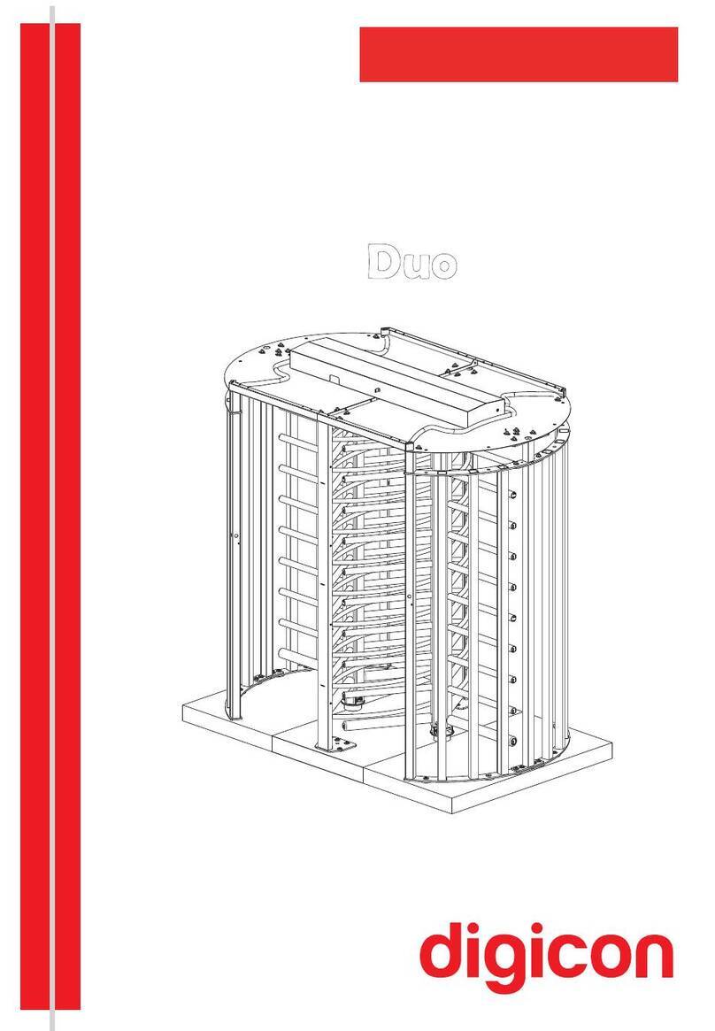
digicon dflow User manual

1
Product Manual

2
© Copyright– Digicon S.A.
Controle Eletrônico para Mecânica – 2017
All rights reserved. No part of this publication may be reproduced, transmitted,
transcribed, stored in a retrieval system, or translated into any language or computer
language of any electronic, magnetic, optical, chemical, manual or other means
without the express written permission of Digicon S.A.
Code: 069.31.220
Version: 04 - English
This manual was elaborated by: Digicon S.A. Controle Eletrônico para Mecânica
Documentation Sector – EDS

3
Contents
1. Important instructions .........................................................................
2. Safety Instructions ..............................................................................
2.1 Symbols ...........................................................................................
2.2 Installation Site .................................................................................
2.3 General Servicing Precautions .............................................................
2.4 General Operation Precautions ............................................................
3.Guidelines ...........................................................................................
4.Presentation ........................................................................................
5.Features of dFlow ................................................................................
5.1 Operation of dFlow ...........................................................................
6. Installation and asembly ......................................................................
6.1 Opening the package .........................................................................
6.2 Fastening on the floor/ground .............................................................
6.2.1 Required free area ..........................................................................
6.3 Access to dFlow after assembly ..........................................................
6.4 Connections between equipent ............................................................
6.5 Overhead detection system .................................................................
6.5.1 Overhead detection system Installation ..............................................
6.5.2 Sensor supply ................................................................................
6.5.3 Sensor communication ....................................................................
6.6 dFlow power supply ..........................................................................
6.7 Selector switch .................................................................................
6.8 dFlow Pictograms .............................................................................
7.Optional Items .....................................................................................
7.1 Card collector kit/Box kit ....................................................................
7.2 Display .............................................................................................
7.3 Antennas ..........................................................................................
7.4 Bar Code Reader ...............................................................................
7.5 Biometrics ........................................................................................
7.6 MCA ................................................................................................
8. Troubleshooting ..................................................................................
9. Technical characteristics .......................................................................
9.1 Dimensions .......................................................................................
9.2 Additional Information ........................................................................
10.Cleaning ...........................................................................................
10.1 Door maintenance and storage ..........................................................
10.2 Maintenance and preservation of the passage control sensor .................
10.3 Maintenance and preservation of dFlow (glass and stainless steel plates)
11.Warranty and technical assistance ........................................................
04
05
05
06
07
08
08
08
09
11
12
12
12
18
19
20
22
23
26
27
28
29
30
31
31
32
32
32
33
33
34
35
35
37
38
38
38
38
39
4
1. Important instructions
Below are the symbols that will appear throughout the manual, indicating
important moments. It is essential to pay close attention to them.
TIP: It will tell you something that Digicon considers
important.
CAUTION: Indicates when you must be very careful when
handling the equipment/product.
ATTENTION: It shows the moment that your observer
posture must be as productive as possible.
INFORMATION: It presents curiosities about the
acquired product.
QR CODE: It presents additional information or links that
better detail the presented text.

5
2. Safety Instructions
2.1 Symbols
ŸRead and Retain Instructions
Carefully read all safety and operating instructions before operating this equipment, and
retain them for future reference.
ŸFollow Instructions and Heed Warnings
Follow all operating and use instructions. Pay attention to all warnings and cautions in the
operating instructions, as well as those that are affixed to this equipment.
ŸTerminology
The terms defined below are used in this document. The definitions given are based on
those found in safety standards.
Service Personnel - The term service personnel applies to trained and qualified individuals
who are allowed to install, replace, or service electrical equipment. The service personnel
are expected to use their experience and technical skills to avoid possible injury to
themselves and others due to hazards that exist in service and restricted access areas.
User and Operator - The terms user and operator apply to persons other than service
personnel.
Ground(ing) and Earth(ing) - The terms ground(ing) and earth(ing) are synonymous.
This document uses ground(ing) for clarity, but it can be interpreted as having the same
meaning as earth(ing).
ŸElectric Shock Hazard
This equipment meets applicable safety standards.
You may find this symbol in the document that accompanies this product. This
symbol indicates important operating or maintenance instructions.
You may find this symbol affixed to the product. This symbol indicates a live
terminal where a dangerous voltage may be present.
You may find this symbol affixed to the product. This symbol indicates a
protective ground terminal.
WARNING
To reduce risk of electric shock, perform the instructions that are
included in the installation and operating instructions. Refer all servicing
to qualified service personnel only.
WARNING
To reduce risk of electric shock, before servicing, turn off the
equipment's electrical power by switching the circuit breaker to the OFF
position. Refer all servicing to qualified service personnel only.

6
Electric shock can cause personal injury or even death. Avoid direct contact with
dangerous voltages at all times. The protective ground connection, where provided, is
essential to safe operation and must be verified before connecting the power supply.
Know the following safety warnings and guidelines:
Dangerous Voltages
· Only qualified service personnel are allowed to perform equipment installation or
replacement.
· Only qualified service personnel are allowed to remove chassis covers and access
any of the components inside the chassis, other than the card collector or circuit
breaker.
· Before servicing, turn off the equipment's electrical power by switching the circuit
breaker to the OFF position.
Grounding
· Do not violate the protective grounding by using an extension cable, power cable,
or autotransformer without a protective ground conductor.
· Take care to maintain the protective grounding of this equipment during service or
repair and to re-establish the protective grounding before putting this equipment
back into operation.
2.2 Installation Site
When selecting the installation site, comply with the following:
Protective Ground - The protective ground lead of the building's electrical installation
should comply with national and local requirements.
Environmental Condition – The installation site should be dry, clean, and ventilated.
Do not use this equipment where it could be at risk of contact with water. Ensure that this
equipment is operated in an environment that meets the requirements as stated in this
equipment's technical specifications, which may be found on this equipment's data
sheet.
ŸInstallation Requirements
ŸCircuit Overload
Know the effects of circuit overloading before connecting this equipment to the power
supply.
A readily accessible disconnect device shall be incorporated external to the equipment.
WARNING
Allow only qualified service personnel to install this equipment. The
installation must conform to all local codes and regulations.
CAUTION
Consider the connection of this equipment to the supply circuit and the
effect that overloading of circuits might have on overcurrent protection
and supply wiring. Refer to the information on the equipment-rating
label when addressing this concern.

7
2.3 General Servicing Precautions
Be aware of the following general precautions and guidelines:
. Servicing - Servicing is required when this equipment has been damaged in any
way, such as power supply cord or plug is damaged, liquid has been spilled or
objects have fallen into this equipment, this equipment has been exposed to rain
or moisture, does not operate normally, or has been dropped. Before servicing,
turn off the equipment's electrical power by switching the circuit breaker to the
OFF position. Refer all servicing to qualified service personnel.
· Wristwatch and Jewelry - For personal safety and to avoid damage of this
equipment during service and repair, do not wear electrically conducting objects
such as a wristwatch or jewelry.
· Lightning - Do not work on this equipment, or connect or disconnect cables,
during periods of lightning.
· Labels - Do not remove any warning labels. Replace damaged or illegible warning
labels with new ones.
· - Do not open the cover of this equipment and attempt service unless Covers
instructed to do so in the instructions. Refer all servicing to qualified service
personnel only.
· - Do not allow moisture to enter this equipment.Moisture
· - After service, assemble this equipment and perform safety Safety Checks
checks to ensure it is safe to use before putting it back into operation.
Ÿ Electrostatic Discharge
Electrostatic discharge (ESD) results from the static electricity buildup on the human
body and other objects. This static discharge can degrade components and cause
failures.
Take the following precautions against electrostatic discharge:
ŸKeep components in their anti-static packaging until installed.
ŸAvoid touching electronic components when installing a module.
WARNING
Avoid electric shock! Opening or removing this equipment's cover may
expose you to dangerous voltages.
WARNING
To reduce risk of electric shock, before servicing, turn off the
equipment's electrical power by switching the circuit breaker to the OFF
position. Refer all servicing to qualified service personnel only.
CAUTION
These servicing precautions are for the guidance of qualified service
personnel only. To reduce the risk of electric shock, do not perform any
servicing other than that contained in the operating instructions unless
you are qualified to do so. Refer all servicing to qualified service
personnel.

8
3. Guidelines
4. Presentation
When innovation meets robustness and design meets reliability, you find the best
solution in access control. Digicon presents a solution designed in the smallest
details to bring innovation, quality and design to the access control market. dFlow
is born as a result of an intense research process in world trends and an exhaustive
engineering work.
2.4 General Operation Precautions
Be aware of the following precautions and guidelines.
· Do not leave kids unattended close to the equipment.
· Do not sit or stand on the equipment.
· Do not lean against the equipment's doors.
ŸRead the information carefully before using the product, this will ensure correct
use of the equipment and the maximum benefits of its technical resources,
besides extending its useful life.
ŸThis product is not waterproof, i.e. it is designed to use in covered environments.
Ÿ Keep this manual for future reference.
Ÿ Digicon reserves the right to modify the characteristics of its products at any time
o adapt them to the latest technological developments.
ŸDigicon reserves the right to change the information contained in this
manualwithout prior notice.
ŸDigicon does not give any contractual warranty regarding the information
contained herein and cannot be held responsible for errors that it may contain or
for problems caused by its use.
ŸThe information herein is the exclusive property of Digicon and protected by
copyright law.
ŸThis manual may not be reproduced, photocopied or translated, in whole or in
part, in any type of media, without Digicon’s written authorization.
ŸThe equipment described herein is customizable, i.e., all possible models are
described herein and do not necessarily reflect the equipment purchased by the
customer.

9
5. Features of dFlow
It is a new way of perceiving access control. The doors are in the normally open
position. Traditional access control equipment has its barriers in the normally
closed position. It is this paradigm shift that differs the dFlow from the other
access control equipment that is available today.
INFORMATION: dFlow is a reliable device and it can be supplied with
the option of normally closed doors
dFlow is the first access control device that fits perfectly into the Free Flow concept.
Although it appears that dFlow is always open, it has doors. They are activated
only when one or more unauthorized persons, including “rider users”, attempt
to pass. The closing system is fast and accurate, being provided by new sensor
systems and sophisticated algorithms that control the acceleration and direction of
the user’s movement. Effectively, passing through dFlow makes it a very pleasant
and fast experience for authorized users and it brings unprecedented security
levels.
The technology, developed in Brazil by Digicon, is able to detect with high
accuracy, one or more users moving in any direction within the passage area. This
accuracy allows doors to be normally open to authorized users and closed only to
unauthorized users.
Indicative windows with LEDs accompany the user during the course through
dFlow, with different colors for different groups of users. In a school application,
for example, students can be followed by a green window, educators by a yellow
window and family members by a blue window. Unauthorized users will be followed
by a red window. The flexibility of dFlow allows other groups of users to be
identified by an extensive range of colors.
dFlow accepts the main traditional identification technologies, including barcode,
RFID, MIFARE and biometrics such as fingerprint. Integration with these technologies
follows the normal standards used in traditional access control equipment. dFlow
is also ready for new emerging contactless biometric technologies. Facial or iris
identification and “finger on the fly”. These new concepts give dFlow even more
speed and a totally contactless experience for the user, which are perfectly aligned
with the new Free Flow paradigm.

10
It can be configured for unidirectional and bi-directional access and with any
passage width, from the traditional 500mm to 900mm (PNE passage). By identifying
multiple users, including PNEs, a 900mm dFlow can be used by common users with
the same 500mm dFlow identification efficiency. Using dFlow with its exclusive
system of normally open doors in wider configurations allows passage comfort for
users, even going in opposite directions.
The dFlow imaging system is equivalent to a virtually unlimited number of
traditional IR sensors, bringing a new level of accuracy to identify unauthorized
users. The algorithms developed by Digicon itself allow controlling the passage
based on this information. They are able to identify and follow multiple users
entering or leaving the passage area. The result is a new, more accurate and
reliable level of identification for “rider users”, whether they are in front of, behind
or even on the side of authorized users.
The doors are swing gates. The algorithm allows the doors to close at a speed
proportional to the speed and positioning of one or more unauthorized users in the
passage area. Once prevented from entering, the doors open again as unauthorized
users move away from them.

11
5.1 Operation of dFlow
Figure 01
dFlow, for opening and closing the doors, uses the exclusive motor control that
enables a controlled, soft, quiet and comfortable turn for the user.
The drive unit is driven via direct current but converted through the drive to PWM
signals for subsequent drive of the coil assemblies.
The drive mechanism of the equipment is sealed type and built in robust housing,
with heat dissipation by natural convection, having its mechanical elements,
subject to support efforts, permanently lubricated.
Some motor characteristics:
• Robust
• Reliable
• High performance
• Electronic control
• Silent (Noise: <45dB)

12
6. Installation and assembly
6.1 Opening the package
Since dFlow is configurable equipment, it is extremely important that careful
visual inspection be done before starting the installation and assembly process.
Digicon’s packaging is accompanied by a checklist, which guides this inspection. If
any part is missing, contact a Digicon sales representative immediately.
WARNING
Allow only qualified service personnel to install this equipment. The
installation must conform to all local codes and regulations.
6.2 Fastening on the floor/ground
The figure below indicates the fastening points of the product on the floor/ground.
The surface must be firm and level, to ensure proper operation of the overhead
detection system and to maintain alignment of the doors.
It must be fastened with mechanical anchor bolts, also known as parabolt or
through chemical fastening.

13
- Fixing points - Optional fastening points
ATTENTION: It is very important to check, during installation, the doors'
alignment when closed. The distance must be the same, from the door's top
to its bottom.
ATTENTION: Check the dFlow model being installed and make sure the
gateway span is correct (there are two models: 500 and 900).
1600
250 250
320 320
230 230
(62.99")
(12.59") (9.84")
(37.007"/21.259")
(9.84")(9.05")
Cable passage
280 280
220 220
220
190 190
60
90
160
(11.02") (11.02")
(8.66") (8.66")
(8.66")
(3.54")
(6.29")
(22.36")
(7.48") (7.48")
(9.05")
(12.59")
940/540
1010/610
1100/700
(39.763"/24.015")
(43,307"/27.559")
TIP:
To tighten the screws, use a long extensor tool.
INFORMATION: dFlow’s measures are shown in millimeters and
(inches).
Figure 03

14
Passage free span:
Transmitter Receiver/Transmitter Receiver
Figure 04
With the ratchet fastening holes, install the fastening threaded bars according to
the figure below. Digicon recommends using Hilti’s capsule chemical anchoring
system (www.hilti.com).
INFORMATION: Chemical fastening is
recommended, but if preferred, use parabolt,
make sure that the floor/ground is adequate..
940mm
920mm
(37.007")
540mm
520mm
(21.259")
(20.472") (36.220")
INFORMATION:
ŸD i g i c o n m e e t s t h e
regulation ABNT NBR 9050
f o r A c c e s s i b i l i t y t o
buildings, furniture, space,
and urban furniture.
Bumper
ŸEach dFlow gateway has 2 bumpers
(left and right) which protect the
equipment against mechanical shocks.
The bumpers, with 10mm each, reduce
the clear width of the gateway from
940/540mm to 920/520mm in the
operating area only.

15
Step by step:
1. Using a 12mm drill (0.47”) make a 90mm deep hole. (Threaded bar M10);
2. Clean the hole with a blower or vacuum cleaner to remove the dust residue;
3. Place the threaded bar into the hole to measure the depth. The bar has a mark
that must be close to the floor/ground;
4. Place the HVU capsule into the hole;
5. Fasten the threaded bar to the drill and tighten it until it hits the bottom of the
hole or until the mark of the threaded bar is close to the floor/ground;
6. Use the drill until the chemical material rises to the surface;
7. Do not touch the threaded bar to allow time for the chemical reaction (10 min);
8. The curing time is according to the table:
Curing time under general conditions
Data according to ETA-05/0255/0256/0257, edition 2010-03-01 /
2006-01-20
Base material temperature Curing time necessary for the fastening to
receive the tcu total load
20°C to 40°C 20 min
10°C to 19°C 30 min
0°C to 9°C 1 h
-5°C to - 1°C 5 h

16
9. Tightening torque and other information can be seen in the table below:
Installation details

17
Cableway Cableway
Cableway Cableway
Cableway Cableway
PASSAGE BOXES
50 mm diameter conduit
Exit
Passage 1 Passageassage 2
6"x6"
Figure 05
INFORMATION: The images above represent a two-passage
installation. For a greater number of passages, assess the amount of
cables and diameter of the ducts.
TIP: Separate the power grid from the logic network.
INFORMATION: The colors of the cables are illustrative.
Preferencial
passage boxes
for AC cable
Preferencial
passage boxes
for AC cable

18
6.2.1 Required free area
dFlow has user detection sensing inside the dFlow at the start of the entrance
and exit. Therefore, a free area must be foreseen in these areas, as shown below:
INFORMATION: In this free area, no type of object must be placed,
which stands still and the floor/ground must be uniform. Some
examples of objects are: Cones, suitcases, pots of plants and flowers,
line organizers, and others.
1000
1600
1000
Free area
Free area
Figure 06
(39,37") (39,37")
(63")
INFORMATION: dFlow is designed to work alone or side by side as
long as the frequency of each overhead detection system (camera) is
different.

19
6.3 Access to dFlow after assembly
Once dFlow is installed and assembled, access to the inside of the equipment can
be done with the key that comes with the equipment by four ways:
• By the two side doors (inside dFlow);
• By the access door to the motor and to the electrical panel on the lower side
and on both sides of dFlow.
Figure 07
Other motors and
communication
connectors
Access cover to the electrical
panel and motor
Circuit breaker
access cover
WARNING
Avoid electric shock! Opening or removing this equipment's cover
may expose you to dangerous voltages.
WARNING
To reduce risk of electric shock, before servicing, turn off the
equipment's electrical power by switching the circuit breaker to the
OFF position. Refer all servicing to qualified service personnel only.
Figure 08 Figure 09
Opening the doors: Closing the doors:

20
2
6"x6"
Figure 12
Panel viewed from the front
Control board
CPU
Figure 10
Switch 5V supply
CPU supply
12V supply
Figure 11
Top view of panel:
6.4 Connections between equipment
The connection cables are located on the dFlow Receiver and must pass through
the ducts as below:
Communication cable connector duct
• 037.12.377
• 037.12.378
• 037.12.379
• 037.12.380
AC Cable Connector Duct
• 037.12.376
Cableway Cableway
Cableway Cableway
Cableway Cableway
PASSAGE BOXES
50 mm diameter duct
Exit
Passage 1 Passage
WARNING
To reduce risk of electric shock, before servicing, turn off the
equipment's electrical power by switching the circuit breaker to the
OFF position. Refer all servicing to qualified service personnel only.
CAUTION
Risk of explosion if battery is replaced by an incorrect type.
Dispose of used batteries according to national and local instructions.
Other manuals for dflow
1
Table of contents
Other digicon Turnstile manuals
Popular Turnstile manuals by other brands

Oxgard
Oxgard Cube C-01 MAINTENANCE OPERATIONS

Alvarado
Alvarado EDC Installation and maintenance instructions

Alvarado
Alvarado TAS12-EDM installation instructions

DELEX
DELEX DSI ES8302 Dual Arm Installation and operation instruction

HIK VISION
HIK VISION DS-K3G411LX Series user manual

GASTOP
GASTOP BR2 instructions

Controlled Access
Controlled Access Tiffany T80-T Service & installation manual

LBA GROUP
LBA GROUP LBAT10 operating instructions

CAME
CAME GUARDIAN installation manual

Gunnebo
Gunnebo RotaSec B120S Installation, operation and maintenance manual

ZKTeco
ZKTeco TS2000 Pro Series user manual

Alvarado
Alvarado SW1000 Assembly, installation and operation instructions