DSP AD1200 User manual

AD1200

AD1200 Installer Manual, Rev. 19.06.2013 1 www.dsp-technology.com
Introduction
Features
Technical Specifications
Installation
Wiring Terminals
Wiring Diagram AD1200 - ST6100, ST6500 & ST6600
Installer Programming
Enter Installer Programming Code
Programming New Installer Code
Recall New Installer Code
Burn In Installer Code
Setting Pulse or Tone Dialling
Operating Through PABX IMPROVED FEATURE
Deleting PABX Line Extension Number
Programming Audible Alert After Alarm Dialling
Programming Dial Cycles NEW FEATURE
Programming Alarm Input
Programming Entry Exit Timing NEW FEATURE
Entering Telephone Numbers IMPROVED FEATURE
Programming Slow Dialling Telephone Numbers
Recall Entered Telephone Numbers
Deleting A Telephone
Deleting All Telephone Numbers
Recording Voice Message
Exit Installer Programming
Enter Installer Test Mode
Exit Installer Test Mode
Enabling and Disabling of Remote Device Functionality NEW FEATURE
Recording and new Remote Device NEW FEATURE
Deleting a Remote Device NEW FEATURE
Deleting all eight Remote Devices NEW FEATURE
Setting Remote Device Type NEW FEATURE
Reset All Programmable Locations to Factory Default
Hardware Reset to Factory Default Settings
User Mode / User Programming
Entering User Programming
Change User Code
Change Telephone Number No.1
Display Telephone Number No.1
Exit User Programming and Arming the System
User Operation
Switching Off or Switching to Standby Mode
Activating Silent Alarm IMPROVED FEATURE
Alarm Memory
Reset Alarm Memory
Installation Programming Notes
CONTENTS ENGLISH
1.00
1.01
1.02
1.03
1.04
1.05
2.00
2.01
2.02
2.03
2.04
2.05
2.06
2.07
2.08
2.09
2.10
2.11
2.12
2.13
2.14
2.15
2.16
2.17
2.18
2.19
2.20
2.21
2.22
2.23
2.24
2.25
2.26
2.27
3.00
3.01
3.02
3.03
3.04
3.05
4.00
4.01
4.02
4.03
4.04
5.00
2
2
2
2
3
3
4
4
4
4
4
4
4
4
5
5
5
5
6
6
6
6
6
6
6
7
7
7
7
7
7
8
8
8
9
9
9
9
9
9
10
10
10
10
10
11
Section Page No.

AD1200 Installer Manual, Rev. 19.06.2013 2 www.dsp-technology.com
The AD1200 is a single channel telephone speech dialler, with digital voice recorder. It is
recommended that you use it in conjunction with a control panels or as a simple one zone
standalone control panel.
1.00 Introduction
Eight telephone numbers can be programmed with up to 24 digits per number.
Non volatile memory so that in complete power loss, telephone programmed set-
tings, numbers and voice data are saved.
Performs tone, pulse and also through PABX system dialling with multiple attempts
Telephone numbers programmed can be recalled for display
Programmable telephone delay time for each telephone number
Single voice message up to 20 seconds and programmable Entry Exit Timing
Lightning protection at telephone line input
Optional Remote Device functionality for Panic Alarm, Arming and Disarming
1.01 Features
1.03 Installation
1.02 Technical Specifications
Power Supply 10 - 15 Volts DC
Current Drain (Standby) 20mA
Current Drain Dialing (Alarm) 85mA
Alarm (Trigger) Input Programmable 0 or 12 Volts DC
Dimensions 134 X 105 X 30mm
Weight 200g

AD1200 Installer Manual, Rev. 19.06.2013 3 www.dsp-technology.com
1.04 Wiring Terminals
1.05 Wiring Diagram AD1200 to ST6100, ST6500 & ST6600 and other Panels
Terminal Connection Suggested Wire Colour
Trigger Trigger 0V or 12Vdc Blue
0Vdc - Negative Supply (OV) Black
12Vdc + Positive Supply (12+) Red
Line In Telephone Line In Green
Earth Ground/Earth Wire Yellow
Line In Telephone Line In Red
Set Telephone Hand Set Green
Set Telephone Hand Set Red
ST6100 & ST6600 ST6000 & ST6500 & other Panels
+ 12V + 12V
- 12V - 12V
INP INP
SET
SET SET
SET
LINE LINE
LINE LINE
AUX 1 S
+ +
AUX S BELL
+ + +
EARTH
EARTH
Note:
If you are not using the S+ on the ST6100 & ST6600, you can enter engineer programming in
those control panels and change the Switch Positive to 0V. If a secure zone is activated in the
ST6100 or ST6600 the Dialer will dial the programmed numbers. The alarm trigger must be
programmed as 12Vdc.
Enter engineering programming in the ST6100 & ST6600:
Press: 5
Press: 9 Day LED Flashing = 0V
Press: Reset

AD1200 Installer Manual, Rev. 19.06.2013 4 www.dsp-technology.com
2.00 Installer Programming
Programming can only be done, when the unit is in off mode. This is indicated by the PWR LED
extinguished . When 1st connecting power to the AD1200, the PWR LED will come on indicating
unit in standby mode.
The dialler will exit installer programming if no data entering after 2 minutes
To enter off mode, enter in the User Code.
Press: 1 111 Press: ENTER PWR LED extinguished.
If the PWR LED is on after entering user code, re-enter the user code again.
Acceptance of programming is given by 6 short beeps from the buzzer., error tone is indicted by a
long beep.
2.01 Entering Installer Programming Code
Press:
Dot on LED display starts blinking, you are now in installer programming mode.
2.02 Programming New Installer Code
Press: Enter new 4 digit code
2.03 Recall New Installer Code
Press:
2.04 Burn In Installer Code
2.05 Setting Pulse or Tone Dialling
Press:
2.06 Operating Through PABX
If the AD1200 has to call through a PABX system. Program in this location the telephone number
which obtains an outside line. The dialer will wait for a outside line dial tone, before dialing the
programmed telephone numbers. For # press VOICE and for * press CODE
7 7 77 Press: ENTER
CODE 0 ? ? ? ?
READ CODE 0
Press: CODE 9
PROG 0 2 Press: 0 Pulse or 1 Tone
Press: PROG 0 3 Press: ? outside line number
2.07 Deleting PABX Line Extension Number
Press: PROG 0 3 ENTER
The factory default setting is tone, if set to pulse when dialing the telephone numbers the dial LED
will flash. To enabled pulse or tone dialing:
After using this command the Installer Code can not be modified!

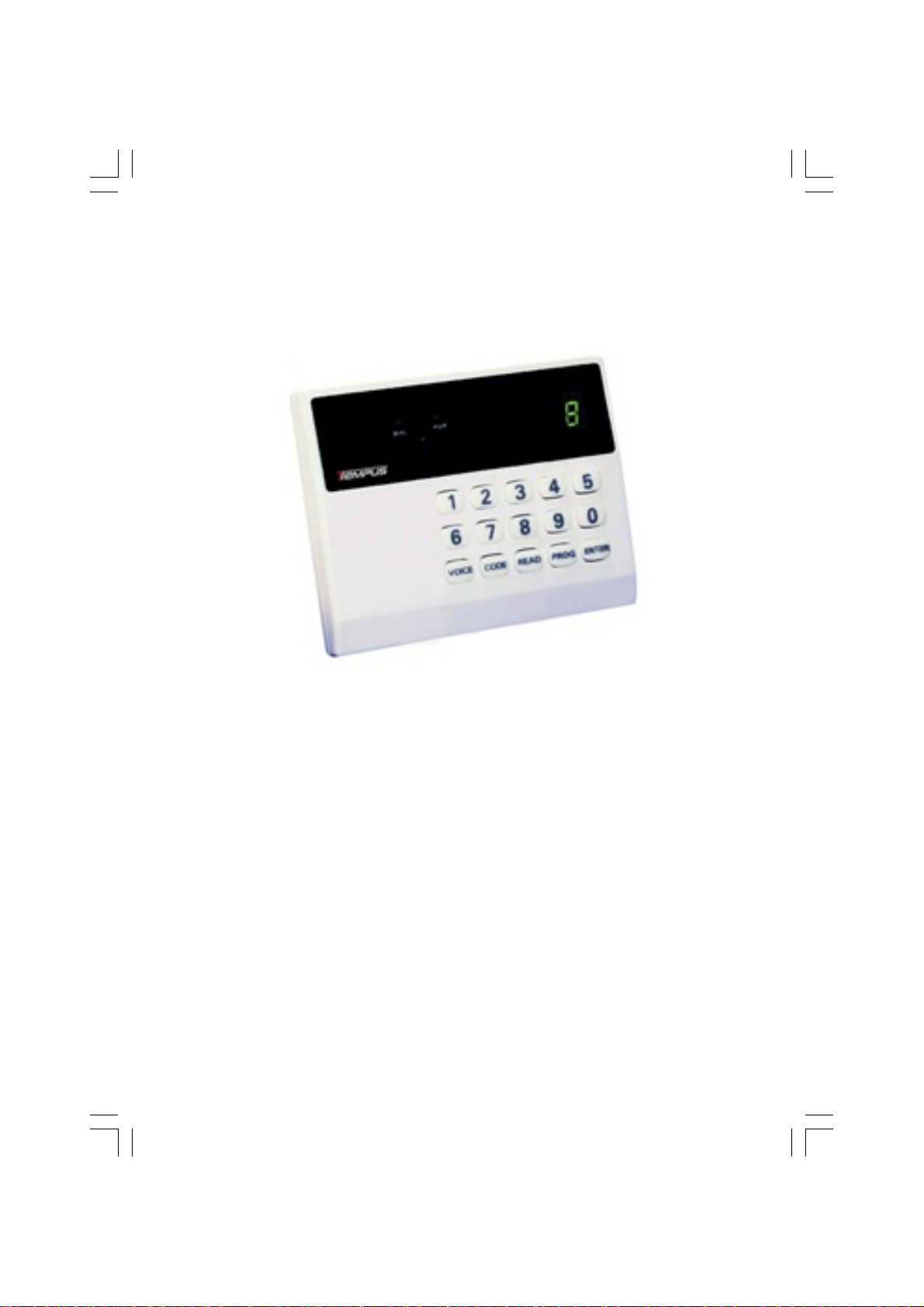
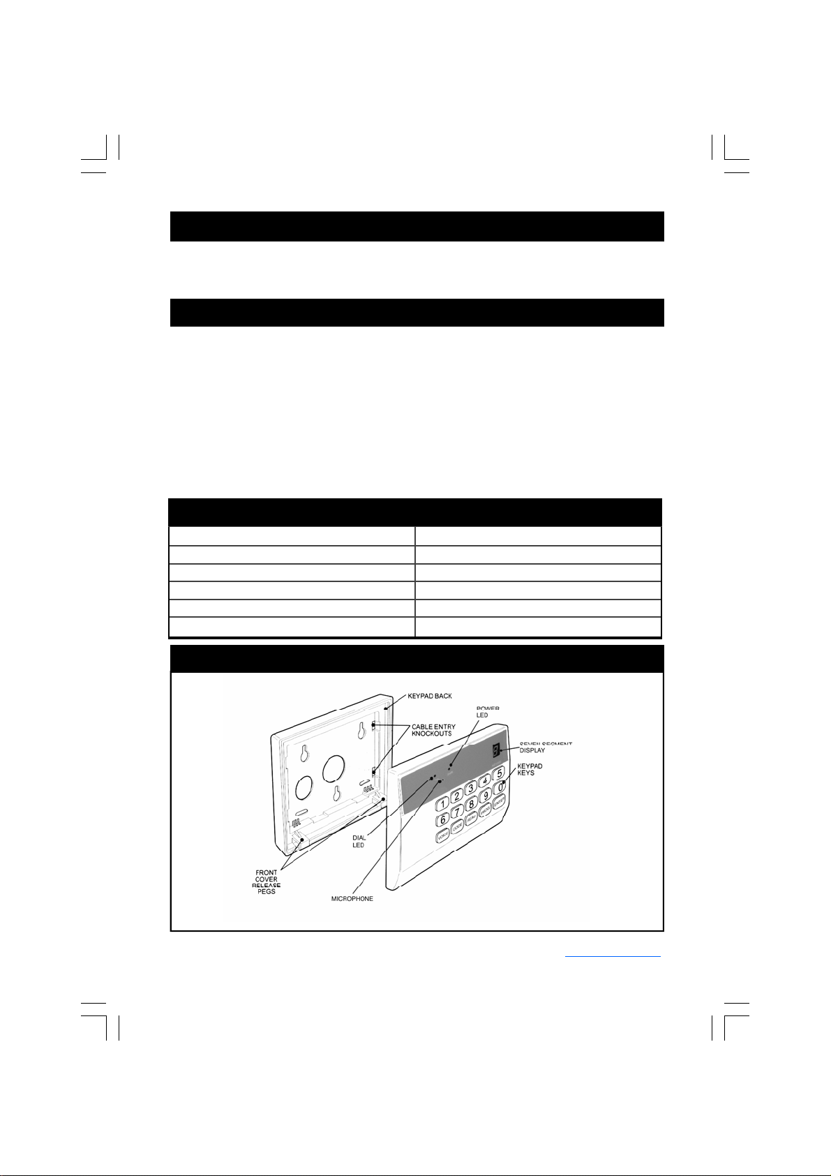
AD1200 Installer Manual, Rev. 19.06.2013 5 www.dsp-technology.com
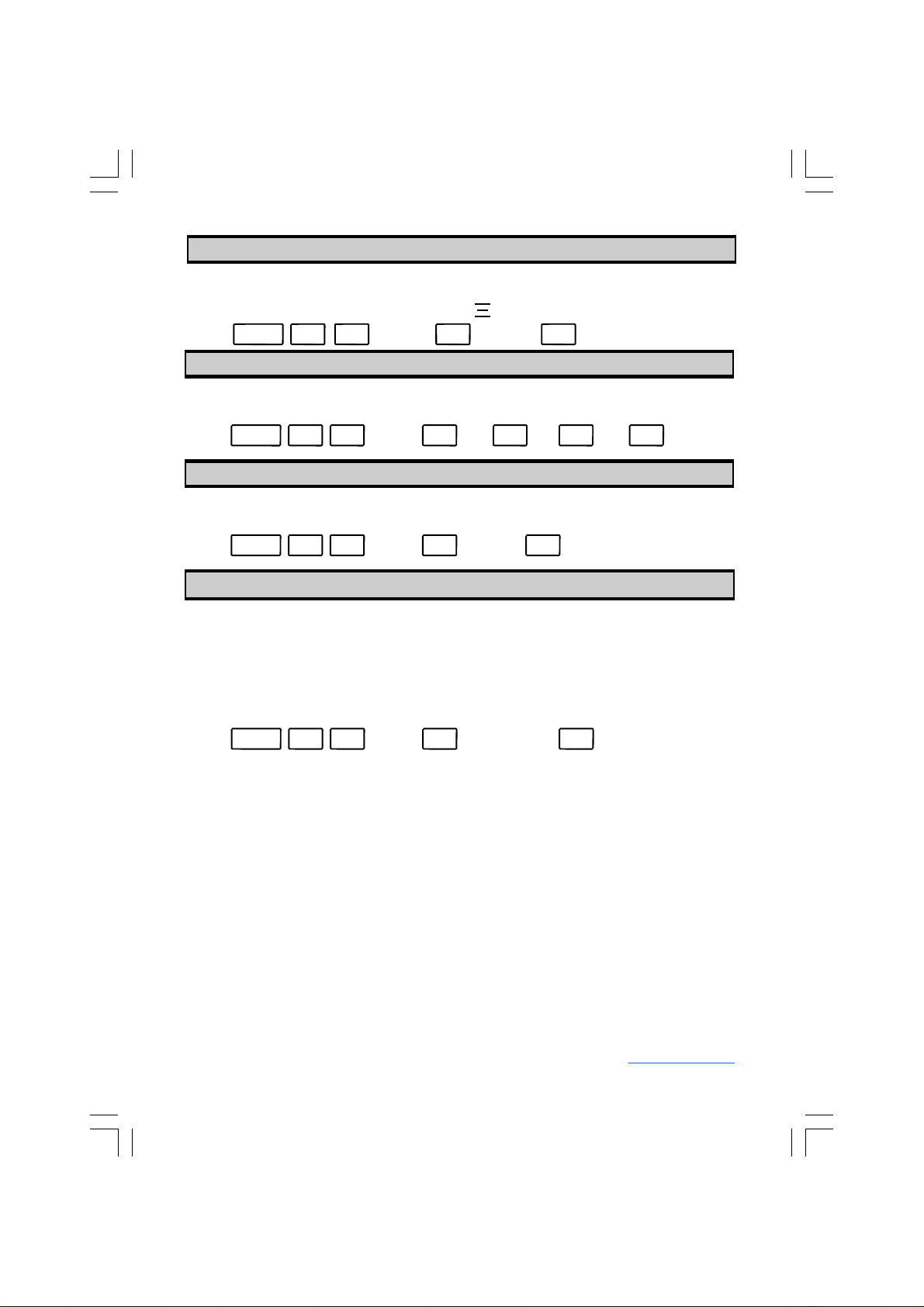
2.09 Programming Dial Cycles
After the dialer has dialed, it can be programmed to give an audible or visual indication. Audio
indication is given by the internal buzzer sounding once dialing has been completed and visual
indication is given on the seven segment display to enabled this function:
Press: PROG 0 4 Press: 0 Visual or 1 Buzzer
2.08 Programming Audible Alert After Alarm Dialling
After dialing all programmed numbers, the dialer can repeat the dialing process up to 3 times.
Therefore the total amount of dial cycles may be programmed. The default setting is 2.
Press: 1 2or 3 4
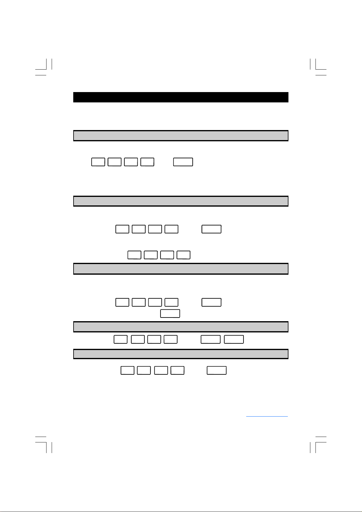
2.11 Programming Entry Exit Timing
The AD1200 provides the possibility to assign an Entry Exit Timing to the Signal Input. This en-
ables the user directly connect detectors (e.g. motion or smoke detectors) to the signal input. In
this case the AD1200 acts like a small independent alarm panel.
Programming a value of 0 will disable this feature (default).
Programming values from 1 … 9 correspond to Entry / Exit Times of 10 … 90 seconds.
PROG 0 5 Press:
If an Entry Exit time greater than 0 is programmed then the system will act as following:
1.) After the user leaves the User Mode the system will start the Exit Timer. The system indicates
the user with beeps that he should leave the premises. Within this time any signal from the input is
masked. No dial attempt will be initiated.
2.) After the user left the premises the system waits for any signal on the input.
3.) If there is a signal on the input then the system will start the Entry Timer. Again the system
indicates the user with beeps to disarm the system with his User Code. While this time no dial
attempt will be initiated.
4.) If the User enters the User Code correctly the system will be disarmed.
5.) If the User does not manage to enter the User code in time the system will initiate an alarm
condition and start the first dial attempt.
2.10 Programming Alarm Input
There is a option of 2 ways to trigger the dialer either by applying 12Vdc or 0Vdc. The default
setting is 12Vdc. To change the trigger input:
Press: 0 112Vdc or 0VdcPROG 0 6 Press:
or or
Press: 0 or key up to 9PROG 0 7 Press:

AD1200 Installer Manual, Rev. 19.06.2013 6 www.dsp-technology.com
2.12 Entering Telephone Numbers
Up to 8 telephone numbers can be programmed, these are in locations 11 – 18. Each telephone
number should not be longer than 24 digits.
Press: PROG 1 1 Enter 1st telephone number to be dialed. ENTERPress:
Repeat the procedure for programming telephone numbers 2 – 8 in locations 12-18.
2.13 Programming Slow Dialing Telephone Numbers
If dialing a telephone number with a connection problem, the AD1200 can be programmed to slow
Press: PROG Enter telephone number location ? ? PROG
appears on the display, enter telephone number Press: ENTER
2.14 Recall Entered Telephone Numbers
Programmed telephone numbers can be recalled and displayed on the seven segment display.
Press: READ PROG Enter telephone number location ? ?
2.15 Deleting A Telephone Number
Press: PROG Enter telephone number location ENTER? ?
2.16 Deleting All Telephone Numbers
Press: PROG 1 9
Press:
2.17 Recording Voice Message
The voice message recoding duration is 20 seconds. The microphone is located between the Dial
& PWR LEDs. To start to record your voices message:
Press: VOICE When releasing the voice key, LED display will show ▬indicating you should
start speaking into the microphone. After 20 seconds the ▬on the display
will extinguish indicating recoding has finished. To playback and listen to voice
message you have to exit installer programming and enter installer test mode.
2.18 Exit Installer Programming
Enter installer code: ? ? ? ? ENTERPress:

AD1200 Installer Manual, Rev. 19.06.2013 7 www.dsp-technology.com
2.19 Enter Installer Test Mode
To listen to the recorded message after recording, a telephone must be connected in parallel with
the telephone line input. If the recording is unsatisfactory you can record again. All telephone num-
bers programmed will be displayed. If telephone number is busy or not answered it will be by-
passed.
Enter installer code: ? ? ?? PROG ENTER
2.20 Exit Installer Test Mode
Enter installer code: ? ? ? ? ENTER
2.21 Enabling and Disabling of Remote Device Functionality
The hardware of the AD1200 provides as an optional feature of connecting 315 or 433 MHz wire-
less Remote Devices like Remote Controls and Remote Panic Buttons.
The Installer may enable this feature as following:
2.22 Recording a new Remote Device
The user has 4s time to activate the remote device and link it to the AD1200.
Note: If the selected location already contains another Remote Device the current location
must be deleted first (refer to 2.23) before linking a new device is possible at this location.
Press:
Press:
2.23 Deleting a Remote Device
To delete a Remote Device follow the following procedure:
2.24 Deleting all eight Remote Devices
Press: PROG 0 8 1
To disable the feature the Installer shall do the following:
Press: PROG 0 8 0
Press: PROG 2 Enter one of the eight Remote Device locations (1 … 8)
If the AD1200 is equipped with the optional Remote Device functionality and the feature is enabled
as described under 2.21 the user can now link up to eight remote devices / functions to the
AD1200. After entering
Press: PROG 2 Enter one of the eight Remote Device locations (1 … 8)
Wait for approximately 4s until an acknowledge sound is played. While this period of time do not
activate any Remote Device. Now the selected location is deleted.
To delete all eight possible Remote Devices enter the following:
Press: PROG 2 9

AD1200 Installer Manual, Rev. 19.06.2013 8 www.dsp-technology.com
2.26 Reset All Programmable Locations to Factory Default
The Installer may reset all programming locations by entering:
Press : ENTER 0 0
2.27 Hardware Reset to Factory Default Settings
Another way to reset all programming locations is the following: Switch the power off, link out the
two pins marked with “Factory Reset”, power up the unit and remove link.
Note: If you have burnt in your Installer Code, the Installer Code can not be reset to the
default value 7777. The unit must be sent back to the factory for repair.
There are no user serviceable parts contained within this unit.
DO NOT attempt to interfere with, or alter any of the electronic components. To do so, may dam-
age the electronic circuitry and will invalidate you warranty.
Every effort has been made to provide accurate information, however, slight variations can occur.
We reserve the right to make changes for the product improvement at anytime.
2.25 Setting Remote Device Type
Each of the eight Remote Devices may be setup to one of the following different functionalities:
Remote Panic Button: Type Code 1
Remote Arming: Type Code 2
Remote Disarming: Type Code 4
Remote Arming / Disarming: Type Code 6
To assigned a type code to a Remote Device the following requirements must be fulfilled:
The hardware of the AD1200 must be equipped with the optional Remote Device function-
ality
The Remote Device feature is enabled as described under 2.21
A Remote device was previously recorded on the desired location as described under 2.22
The installer may now continue the following procedure to set the desired Device Type:
Press: PROG 3 Enter the desired Remote Device locations (1 … 8)
Enter the desired Device Type Code (1, 2, 4 or 6)

AD1200 Installer Manual, Rev. 19.06.2013 9 www.dsp-technology.com
3.00 User Mode / User Programming
3.02 Changing User Code
It is recommended that you change the user code from the factory default setting.
To Change user code:
Enter user code: 1 1 1 1 CODE
Enter new 4 digit code: ? ? ??
3.03 Changing Telephone No.1
For security reasons it is only possible to change the 1st telephone number in user programming.
The telephone number entered should not be longer than 24 digits.
Enter user code: ? ? ? ? PROG
ENTER
3.04 Display Telephone No.1
Enter user code: ? ? ? ? READ PROG
Press:
Press:
Press:
Press: 1 111 Press: ENTER PWR LED extinguished.
Programming can only be done, when the unit is in off mode. This is indicated by the PWR LED
extinguished .
The dialer will exit user programming if no data entering after 2 minutes
If the PWR LED is on after entering user code, re-enter the user code again.
Acceptance of programming is given by 6 short beeps from the buzzer., error tone is indicted by a
long beep.
Enter new telephone number Press:
Dot on LED display starts blinking, you are now in user programming mode.
3.05 Exit User Programming and Arming the System
Enter user code: ? ? ? ? ENTERPress:
3.01 Enter User Programming
To enter off mode, enter in the valid User Code.
If an Entry Exit Time was programmed the Exit Timer will be activated and the system will signal
the user with beeps to leave the premises.

AD1200 Installer Manual, Rev. 19.06.2013 10 www.dsp-technology.com
4.00 User Operation
The AD1200 has two levels of operation Standby and Off mode. In Standby mode the AD1200 is
ready to dial if activated. Standby mode is indicated by illumination of the PWR LED. Off Mode the
AD1200 is not able to dial if activated. Off mode is indicated by the PWR LED extinguished.
4.02 Activating Silent Alarm (operational in Standby as well as in Off Mode)
Enter user code: ? ? ?? ENTER Power LED extinguished.
You can return to standby mode by repeated above sequence.
4.01 Switching Off or Switching to Standby Mode
Press: PROG ENTER simultaneous to activate Silent Alarm / Panic Alarm.
4.03 Alarm Memory
If AD1200 has activated in Standby Mode and dialled, the display will show:
4.04 Reset Alarm Memory
Enter user code: ? ? ?? ENTER
Press:
Press:

AD1200 Installer Manual, Rev. 19.06.2013 11 www.dsp-technology.com
5.00 Installer Programming Notes
Function Factory Default Settings New Settings
User Code 1 1 1 1
Installer Code 7 7 7 7
Pulse Dialing Disabled
Tone Dialing Enabled
PABX Extension Number Clear
Installer Code Burn In Clear
Dialer Memory Audible Disabled
Alarm (Trigger) Input 12 Volts
Telephone No.1 Clear
Telephone No.2 Clear
Telephone No.3 Clear
Telephone No.4 Clear
Telephone No.5 Clear
Telephone No.6 Clear
Telephone No.7 Clear
Telephone No.8 Clear
Slow Dialing Telephone Num- Clear
Dial Cycles 2
Entry Exit Time 0 (OFF)
Recorded Message
Installer Information
Installer Name:
Address:
Address:
Telephone No.:
Date of Installation:
Table of contents
Popular Telephone manuals by other brands

Vodavi
Vodavi IP7008D quick start guide

Interquartz
Interquartz IQ335 operating instructions

Voipac
Voipac NetPhone NP210 user guide

Satellite Hire
Satellite Hire Iridium 9555 user guide

Guardian
Guardian HR70 Installation & operation

TransTel Communications
TransTel Communications TD-1648i installation instructions