Northern Telecom M5212 ACD Operating and installation instructions

297-2041-900
DMS-100 Family
M5212 ACD Set
General Description, Installation, and
Maintenance
BCS33 and up Standard 02.01 October 1991


Publication number: 297-2041-900
Product release: BCS33 and up
Document release: Standard 02.01
Date: October 1991
M5212 ACD Set
General Description, Installation, and Maintenance
BCS33 and up
i
DMS-100 Family
M5212 ACD Set
General Description, Installation, and Maintenance
Information is subject to change without notice. Northern Telecom reserves the right to make changes in design or components
as progress in engineering and manufacturing may warrant.
Copyright Northern Telecom 1991
All rights reserved.
DMS
,
DMS-100, DMS SuperNode
,
MAP, Teladapt, and
NT are trademarks of Northern Telecom.

297-2041-900 Standard 02.01 October 1991
ii
Publication history
October 1991 BCS33 Standard 02.01 release
•Added feature NC0288, Call Park
•Added feature NC0288, Directed Call Park
•Added information about volume settings for recommended headsets
March 1991 BCS32 Standard 01.01 release First release of this document
Revision bars in the table of contents identify the sections where technical
information has been changed. Revision bars in the outside margin of a
page indicate text that has been added or revised.

M5212 ACD Set
General Description, Installation, and Maintenance
BCS33 and up
iii
Contents
About this document v
When to use this document v
How to identify the software in your office v
How M5212 ACD Set documentation is organized vi
References in this document vi
What precautionary messages mean vii
Introduction 1-1
Physical Characteristics 1-1
Dimensions 1-2
External Connectors 1-2
Specifications 2-1
Reliability 2-2
Recommended headsets 2-3
Environmental and Safety Considerations 2-5
Line Engineering 2-5
Powering Requirements 2-6
Operations and features 3-1
Feature descriptions 3-1
Keys 3-1
Alphanumeric Display 3-3
Tone Characteristics 3-3
Loudspeaker 3-4
Feature operations 3-4
Basic features 3-4
Permanently assigned keys 3-5
Assignable feature keys 3-7
Headset operations 3-7
Installation procedures 4-1
Unpacking 4-1
Installation 4-1
Verification procedures and maintenance 5-1
Maintenance 5-1
Verification test routines 5-1
Loop check 5-1

iv Contents
297-2041-900 Standard 02.01 October 1991
Polarity Check 5-2
Station Ringer Test 5-2
Ordering information 6-1
List of terms 7-1
List of figures
Figure 2-1 Wiring scheme for alternate power supply arrangements 2-7
Figure 3-1 M5212 ACD Set 3-2
Figure 4-1 M5212 ACD Set packaging 4-4
Figure 4-2 M5212 ACD Set bottom view 4-5
Figure 4-3 M5212 ACD Set loop connection 4-6
List of procedures
Procedure 4-1 M5212 ACD Set Installation 4-1
Procedure 5-1 Polarity check 5-2
Procedure 5-2 Station ringer test setup 5-2
Procedure 5-3 Station ringer test 5-3
List of tables
Table 1-1 Physical Dimensions 1-2
Table 2-1 LCD status indicators 2-1
Table 2-2 Mute handset LCD indicators 2-2
Table 2-3 Random electronic failures and MTBF 2-3
Table 2-4 Mechanical Failure 2-3
Table 2-5 Recommended headsets 2-3
Table 2-6 Recommended headsets 2-4
Table 2-7 RJ to PJ Adapters 2-4
Table 3-1 Tone Characteristics 3-3
Table 3-2 Headset Operations 3-8
Table 6-1 M5212 ACD set stocklist of field replaceable parts 6-1

M5212 ACD Set
General Description, Installation, and Maintenance
BCS33 and up
v
About this document
This document provides a general description of the M5212, specifications,
operations and feature information, installation procedures, and verification
and maintenance information. Part numbers and ordering information are
also included.
When to use this document
Northern Telecom (NT) software releases are referred to as batch change
supplements (BCS) and are identified by a number, for example, BCS29.
This document is written for DMS-100 Family offices that have BCS33 and
up.
More than one version of this document may exist. The version and issue
are indicated throughout the document, for example, 01.01. The first two
digits increase by one each time the document content is changed to support
new BCS-related developments. For example, the first release of a
document is 01.01, and the next release of the document in a subsequent
BCS is 02.01. The second two digits increase by one each time a document
is revised and rereleased for the same BCS.
To determine which version of this document applies to the BCS in your
office, check the release information in DMS-100 Family Guide to Northern
Telecom Publications, 297-1001-001.
How to identify the software in your office
The Office Feature Record (D190) lists your current BCS and the NT
feature packages in it. You can view similar information on a MAP
(maintenance and administration position) terminal by typing
>PATCHER;INFORM LIST;LEAVE
and pressing the Enter key.

vi About this document
297-2041-900 Standard 02.01 October 1991
How M5212 ACD Set documentation is organized
This document is part of M5212 ACD Set documentation that supports the
Northern Telecom line of M5212 ACD Set products. M5212 ACD Set
documentation is a subset of the DMS-100 Family library.
The DMS-100 Family library is structured in numbered layers, and each
layer is associated with an NT product. To understand M5212 ACD Set
products, you need documents from the following layers:
•DMS-100 Family basic documents in the 297-1001 layer
•M5212 ACD Set documents in the 297-2041 layer
M5212 ACD Set documents and other documents that contain related
information are listed in “Finding M5212 ACD Set information” in M5212
ACD Set Product Guide,Product guide.
References in this document
The following documents are referred to in this document.
Number Title
P0726328
M5212 User’s Guide
297-2011-180
DMS-100 Business Set Line Engineering
297-2041-010
Automatic Call Distribution Product Guide
297-2041-101
Automatic Call Distribution Planning and Engineering Guide
297-2041-301
Automatic Call Distribution Administration Guide
297-2041-350
Automatic Call Distribution Translations Guide
207-2041-500
Automatic Call Distribution Tier II Maintenance Guide
297-2041-503
Automatic Call Distribution Trouble Locating and Clearing Guide
297-2041-901
End-User Load Management

About this document vii
M5212 ACD Set
General Description, Installation, and Maintenance
BCS33 and up
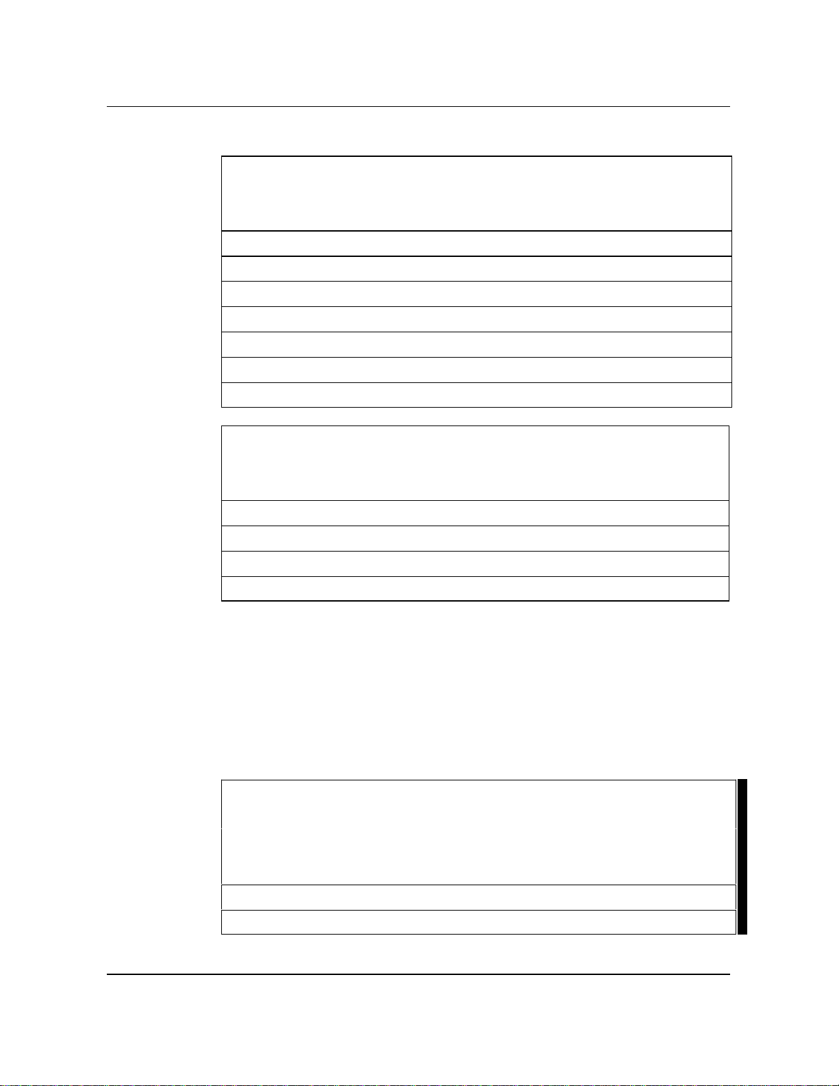
What precautionary messages mean
Danger, warning, and caution messages in this document indicate potential
risks. These messages and their meanings are listed in the following chart.
Message Significance
DANGER Possibility of personal injury
WARNING Possibility of equipment damage
CAUTION Possibility of service interruption or degradation
Examples of the precautionary messages follow.
DANGER
Risk of electrocution
The inverter contains high voltage lines. Do not open the front
panel of the inverter unless fuses F1, F2, and F3 have been
removed first. Until these fuses are removed, the high voltage
lines inside the inverter are active, and you risk being
electrocuted.
WARNING
Damage to backplane connector pins
Use light thumb pressure to align the card with the connectors.
Next, use the levers to seat the card into the connectors. Failure
to align the card first may result in bending of the backplane
connector pins.
CAUTION
Loss of service
Subscriber service will be lost if you accidentally remove a card
from the active unit of the peripheral module (PM). Before
continuing, confirm that you are removing the card from the
inactive unit of the PM.


M5212 ACD Set
General Description, Installation, and Maintenance
BCS33 and up
1-1
Introduction
The M5212 ACD telephone set with display and two headset ports has been
designed specifically for use with ACD applications. The M5212 is
equipped with:
•11 buttons with associated liquid crystal display (LCD) indicators that
may be assigned to features or line appearances
•One button with associated LCD indicator for handset mute off/on
•HOLD, RELEASE, and VOLUME CONTROL keys
•2 X 24 alphanumeric display
•12-key dialpad
•Modular ports for headset support
The alphanumeric display module is mounted at the rear top edge of the
telephone and is hinged so that the viewing angle can be adjusted physically
to reduce glare and maximize contrast. The maximum display capacity of
the screen is two rows of 24 characters each.
The M5212 may be equipped with one to three M518 18-button add-on
units, or with one M536 36-button add-on module. Alternatively, a
combination of one M536 and one M518 add-on units may be used.
Physical Characteristics
The phone is available in either chameleon-gray or black. Feature and line
appearance keycaps are medium dolphin gray. The IN CALLS keycap is
green, the HOLD key is red, and the RELEASE key is orange. The line
cord is silver satin.

1-2 Introduction
297-2041-900 Standard 02.01 October 1991
Dimensions
The exterior dimensions of the M5212 ACD set are:
Table 1-1xxx
Physical Dimensions
Dimension MM Inches
length 226.5 8.8
width 208.0 8
height (front) 27.5 1.1
height (rear) 73.5 2.88
External Connectors
The modular jacks for the line cord, handset cord and headset cord are
located on the bottom of the set. Figure 4-2 on page 4-5 shows the
underside of the telephone base with handset and line cord channels, and a
connecting cord channel for installations where the telephone is equipped
with add-on modules. Figure 3-1 on page 3-2 shows and labels the user
accessible main components of the M5212 ACD set.

M5212 ACD Set
General Description, Installation, and Maintenance
BCS33 and up
2-1
Specifications
The M5212 ACD set meets or exceeds the functionality standards currently
attained by other members of the M5000 terminal portfolio.
LCD Indicators
The M5212 has 12 feature keys with associated LCD indicators. Of these
12 keys, 11 are assignable, and one has a fixed position. The LCD
indicators reflect the following states:
Table 2-1xxx
LCD status indicators
Function LCD State
Idle LCD Off
Active LCD On
Ringing or feature pending LCD Flashing
Hold or feature pending or mute
activated LCD Winking
Feature activation and display messages
Feature activation and display messages are completely controlled by the
DMS-100 Meridian Digital Centrex ACD software using stimulus signaling.
Handset operation and mute control
When the headset is connected, the hookswitch is completely bypassed. If
the headset is connected, taking the handset off-hook and then placing it
back on-hook will not affect the status of a call. When a headset is not
connected, this hookswitch bypass is disabled, and the handset operates as it
would on another business set.

2-2 Specifications
297-2041-900 Standard 02.01 October 1991
One feature button is permanently assigned to toggle the handset mute on or
off. The mute handset LCD indicator will indicate the following states:
Table 2-2xxx
Mute handset LCD indicators
On/Off Hook - Mute On/Off LCD State
Handset on-hook LCD Off
Handset off-hook - mute off LCD Off
Handset off-hook - mute on LCD winking
During operations with a headset connected, the default state for handset
operations is mute on. Pressing the MUTE button one time during a call
places the handset into mute off mode. Once the handset is in the mute off
mode, it will not return to a muted mode until the MUTE button is pressed
again, the handset is placed on-hook, or the REALEASE (Rls) key is
pressed.
Volume control
The VOLUME CONTROL rocker key controls independent volume levels
for the headset, handset, ringer, and speaker. A visual bar indication is
shown on the main display whenever the VOLUME CONTROL key is used.
Headset volume is controlled only during an active call with the handset
on-hook. Once it has been set, the headset volume setting will be
maintained unless auxiliary power is lost to the M5212, the headset is
disconnected, or the volume setting is changed.
Handset volume is controlled during an active call with the handset
off-hook. Once it has been set, the handset volume setting will be
maintained unless power is lost to the M5212, the handset is placed
on-hook, or the volume setting is changed.
Speaker volumes may be adjusted during on-hook dialing and listen on hold.
In addition, the ringer volume can be adjusted while the handset and headset
are seated. Changes to the ringer and speaker volume settings are
maintained as long as auxiliary power is not lost.
Reliability
MTBF (mean time between failure) predictions were made using the
Product Integrity MTBF component database.
Specifications 2-3
M5212 ACD Set
General Description, Installation, and Maintenance
BCS33 and up
Table 2-3xxx
Random electronic failures and MTBF
Item % Failures per Year
Handset Receiver 0.9
Handset Transmitter 0.5
Alphanumeric Display 1.2
Wall Transformer 0.3
Hookswitch 0.3
Electronic Components 4.4
Total 7.6% MTBF = 13.16 years
Table 2-4xxx
Mechanical Failure
Item One failure per years
Handset Cord 70
Line Cord 30
Housing 200
All Mechanical Components 19
Recommended headsets
Northern Telecom has fully tested the following headsets and adapters and
found them to be acceptable from both safety and performance standards:
Note: ”RJ” usually refers to headset types with electret microphones. ”PJ”
usually refers to headset types with carbon microphones. For proper operation
of the headset, ensure that the appropriate type of headset is plugged into the
matching jack on the bottom of the set.
Table 2-5xxx
Recommended headsets
Manufacturer Type Model no. Recommended
Volume Settings
Plantronics PJ HSB552-1, Supra VOL. II
Plantronics RJ MHB528-2, Supra 00110101 VOL. I

2-4 Specifications
297-2041-900 Standard 02.01 October 1991
The following headsets are electrically compatible but have not completed
safety testing:
Table 2-6xxx
Recommended headsets
Manufacturer Type Model no. Recommended
Volume Settings
Northern Telecom
(Liberation) PJ Canada: X9950640 - ear hook
X9950641 - ear loop
X9980642 - headband
U.S.: X9950663 - ear hook
X9950664 - ear loop
X9950665 - headband
NOM-MAX
NOM-MAX
NOM-MAX
NOM-MAX
NOM-MAX
NOM-MAX
Northern Telecom
(Liberation) RJ Canada: X9950644 - MPA
X9950683 - ear hook
X9950684 - ear loop
X9950685 - headband
U.S.: X9950644 - MPA
X9950695 - ear hook
X9950696 - ear loop
X9950697 - headband
TX at 10
Side Tone at 0
Max. at 12
VOL. (MIN-NOM)
TX at 10
Side Tone at 0
Max. at 12
VOL. (MIN-NOM
Plantronics PJ MHB228-2, Starset
HSB343-1, Starset 01110001 VOL. I
VOL. II
ACS PJ
PJ/R
J
RJ
Attendant AT
MCE
ISDN/DMS
Micro-power MP
VOL. 2-3
1,2,3,4,5 for S-3;
3,4,5,6 for S-4
3,5,7,9 for S-3;
6,7,9,10 for S-4
2,6,7 for S-3
WARNING
Potential safety hazard.
Northern Telecom has performed tests to confirm the electric and
acoustical compatibility of these headsets with the M5212. No
test has been performed, and no representation is made, as to the
safety of these headsets.
Table 2-7xxx
RJ to PJ Adapters
Manufacturer Model no.
Plantronics 18709-01

Specifications 2-5
M5212 ACD Set
General Description, Installation, and Maintenance
BCS33 and up
Environmental and Safety Considerations
The M5212 meets the Canadian and U.S. mandatory interconnect
requirements for telephone equipment.
Temperature and Humidity
The M5212 operates within the following conditions:
•Operating state
- Temperature Range: 5 to 50 degrees Celsius
- Relative Humidity 20% to 95% non-condensing,
34% for 30 to 50 degrees Celsius
•Non-operating state
- Temperature Range: -20 to 70 degrees Celsius
- Thermal Shock: from -30 to 70 degrees Celsius,
to room ambient (25 degrees Celsius)
- Relative Humidity: 20% to 95% non-condensing for 0 to 40
degrees Celsius
Electromagnetic Interference
The radiated and conducted electromagnetic interference meets the
requirements of Subpart J or Part 15 of FCC rules for class A computing
devices.
Vibration and shock
The M5212 ACD Set was designed to continue to work to specifications
after being subjected to the following vibrations in each of three orthogonal
directions for 90 minutes:
•Vibration frequency range of 5 to 200 Hz
•Maximum half displacement 0.35 mm (.014 in)
•Maximum acceleration 1.5/m/s/s
In addition, the design of the set accommodates normal handling during
shipment when it is contained in its packaging.
Line Engineering
The M5212 ACD set is designed for direct connection through a non-loaded
subscriber loop pair to a Northern Telecom DMS-100 or DMS-250 Digital
Switching system. It operates to its full potential through twisted pair
wiring on transmission lines selected according to rules detailed in NTP
297-2011-180, DMS-100 Business Set Line Engineering. The maximum
loop length is 4,572 m (15,000 ft) on 26 AWG standard twisted pair
telephone wires.
The interface to the Central Office (CO) equipment is through a business set
(6X21AC) line card in the Line Concentrating Module (LCM) of the

2-6 Specifications
297-2041-900 Standard 02.01 October 1991
DMS-100 or DMS-250. The 6X21AC card supports one business set per
line card.
Powering Requirements
The M5212 ACD set is powered through both its loop connection to the CO
and through an external power supply.
Loop power
Loop power is supplied by a balanced 440 Ohm battery feed from the
switching equipment. The switch battery voltage supplied to the loop is
nominally 52 V dc, with a minimum of 42.75 V dc and a maximum of 56 V
dc. Under normal conditions, the polarity must be negative on the Ring lead
with respect to the Tip lead.
The current drawn from the loop is typically10 mA when the set is idle, and
16 mA when the set is active.
External power
Each M5212 requires an external power supply to be fully operational. If
the external power supply fails, only feature keys 0 through 9, and LCDs 0
through 7 will be operational.
This external power supply must be 16 V ac and must satisfy the following
set current demands:
•Active state local power consumption: Maximum current drawn is
(with 2 carbon equivalent headsets) 120 mA rms (2.2W)
•Idle state local power consumption: Maximum current drawn is
(with no headsets seated) 40 mA rms (0.750W)
Two closet dc power supply units are recommended:
•Shumway; No. TBA, 110 V ac input, 24 V dc, 200mA outputs
•NPS 50220-07.L8; CPC A0352921 (1 circuit), 110V ac, input, 24V dc,
250mA output
When using the closet power supply, the following points should be
observed:
•A separate cable, containing Tip, Ring, and power supply leads, is
required for each M5212 set.
•Each M5212 set is to be connected to a different power supply circuit.
•The run length between the closet power supply and the M5212 must not
exceed 76m (250 ft) of 24 or 22 AWG wire, or 46m (150 ft) of 26 AWG
wire.
•Wire pairs should not be paralleled to reduce feed resistances.
Specifications 2-7
M5212 ACD Set
General Description, Installation, and Maintenance
BCS33 and up
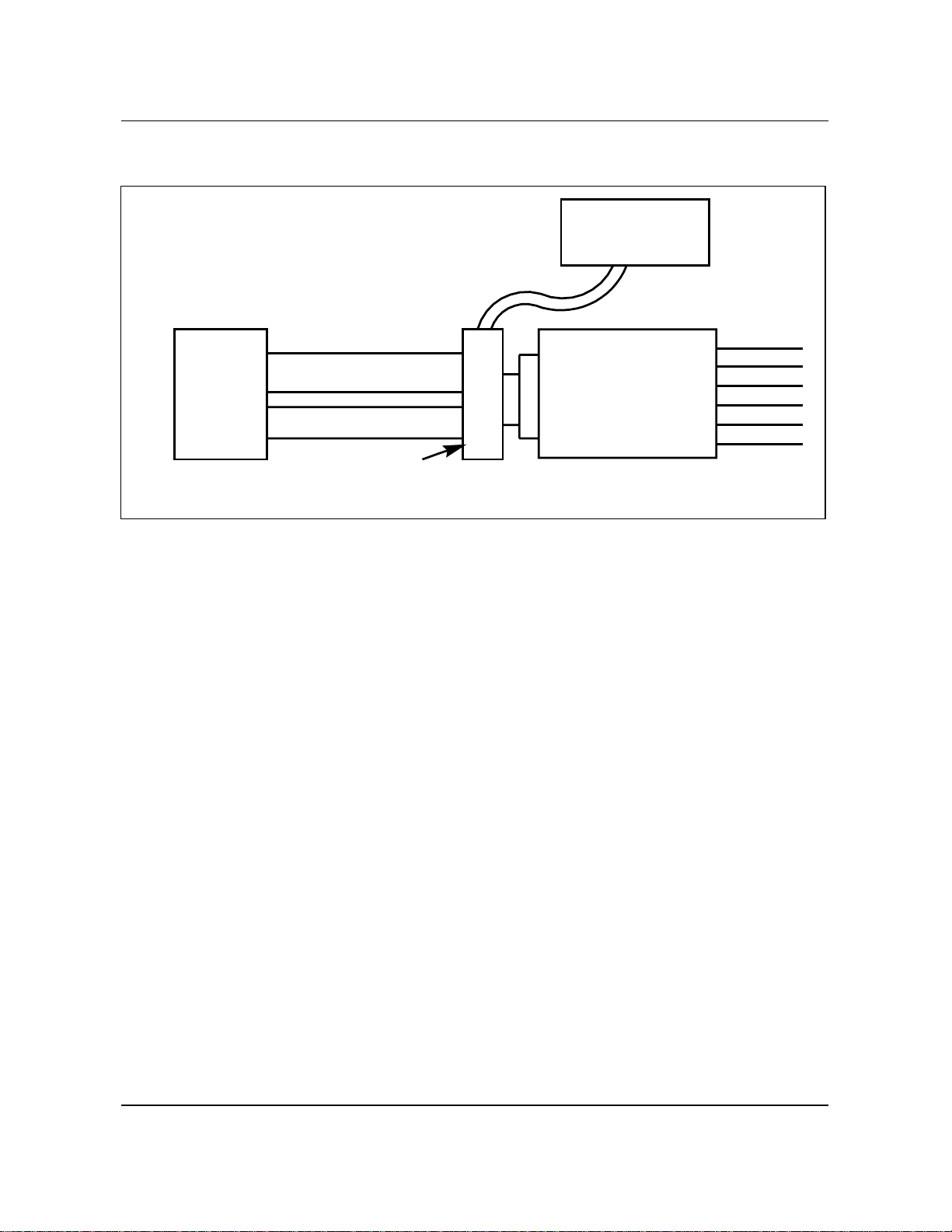
Figure 2-1xxx
Wiring scheme for alternate power supply arrangements
Wall plug-in
Transformer
M5212
ACD
set
AC**
TR
AC**
TR
DC*
Wall-mounted
connecting
box equipped with
Teladapt connector
DC*
T-adapter or I-adapter
NE267QA * Leads wired only if remote dc supply exists
** Leads used only if local plug-in ac power
supply present

Table of contents
Other Northern Telecom Telephone manuals

Northern Telecom
Northern Telecom DMS-100 Series Operating manual

Northern Telecom
Northern Telecom DisplayPhone User manual

Northern Telecom
Northern Telecom IMAGINATION QSK450 Operating and installation instructions

Northern Telecom
Northern Telecom Decorator Series Instruction manual

Northern Telecom
Northern Telecom Logic 10 User manual

Northern Telecom
Northern Telecom M5317TX User manual

Northern Telecom
Northern Telecom Unity Two-Line User manual

Northern Telecom
Northern Telecom DisplayPhone User manual

Northern Telecom
Northern Telecom Compact ICS 4.0 User manual

Northern Telecom
Northern Telecom QSK 100 Instruction Manual


