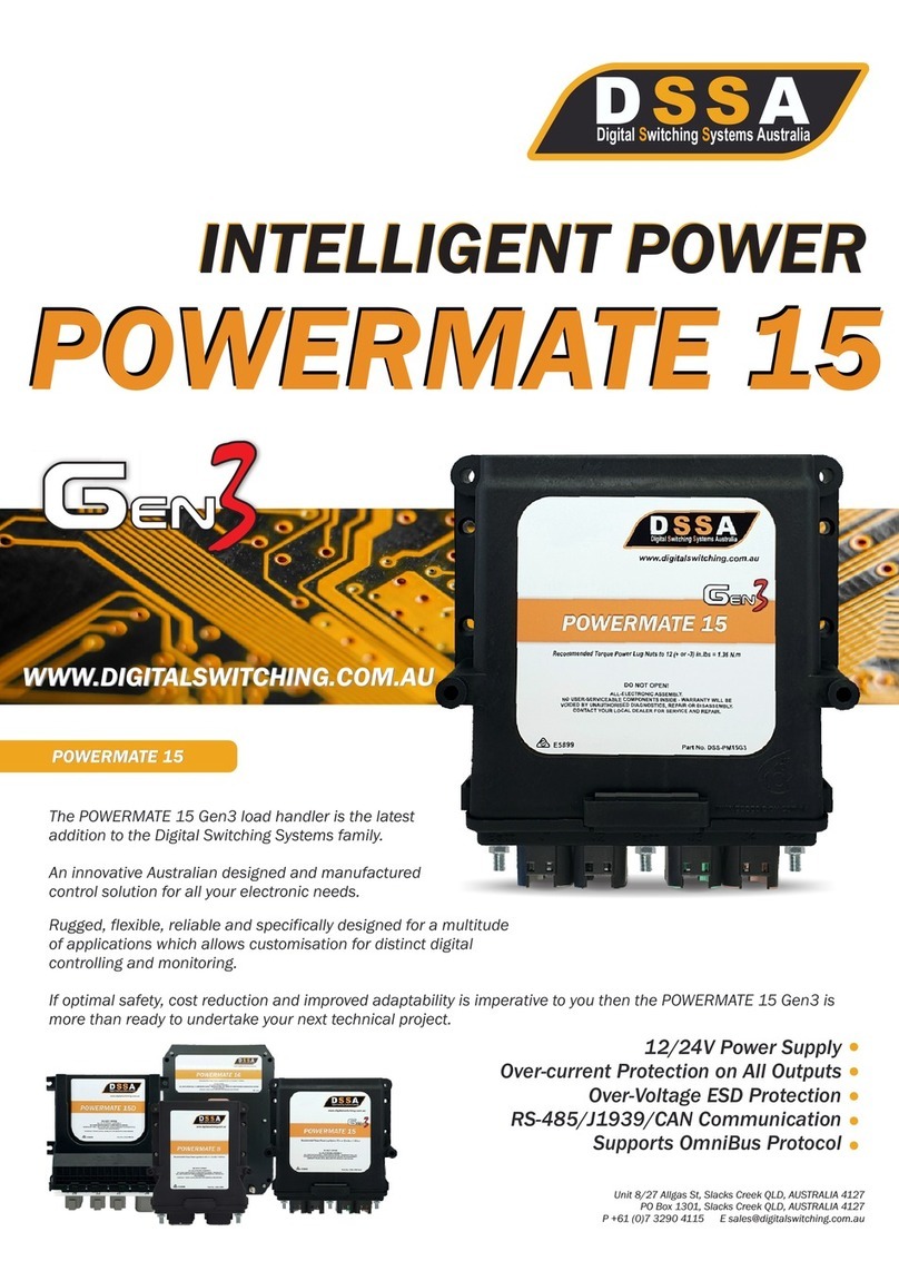
DSSA POWERMATE 16 User manual

POWERMATE 16
POWERMATE 16
12/24V Power Supply
Over-current Protection on All Outputs
Over-Voltage ESD Protection
RS-485/J1939/CAN Communication
Supports OmniBus Protocol
The POWERMATE 16 load handler is the latest addition to the
Digital Switching Systems family.
An innovative Australian designed and manufactured control
solution for all your electronic needs.
Rugged, flexible, reliable and specifically designed for a multitude
of applications which allows customisation for distinct digital
controlling and monitoring.
If optimal safety, cost reduction and improved adaptability is imperative to you then the POWERMATE 16 is more
than ready to undertake your next technical project.
WWW.DIGITALSWITCHING.COM.AU
Unit 8/27 Allgas St, Slacks Creek QLD, AUSTRALIA 4127
PO Box 1301, Slacks Creek QLD, AUSTRALIA 4127
P +61 (0)7 3290 4115 E [email protected]
S S
Digital witching ystems AustraliaS S
A D
POWERMATE 16
INTELLIGENT POWER
INTELLIGENT POWER
POWERMATE 16
S S
Digital witching ystems AustraliaS S
A D

The purpose of this document is to describe the PowerMate 16 which has been designed for the Automotive, Marine,
Mining and RV industries.
PURPOSE
PURPOSE
The standard system will be shipped with the following items:
INCLUSIONS
INCLUSIONS
Description
PowerMate 16 Module
Connection Kit
Pinout Sheet
Quantity
1
1
1
The PowerMate 16 (PM16) receives switch commands from the keypads, interfaces or CANbus and then processes
these commands based on the current system status. The response to a switch command may be an activation or
deactivation of a circuit, the start of a timed function or in systems with keyless ignition the locking or unlocking of
the system.
The PM16 then sends the system status information to turn on/off the indicator LED’s and backlights. The PM16
incorporates solid state technology which uses MOSFET’s for switching and over-current protection.
PURPOSE
PURPOSE
ELECTRICAL FEATURES
ELECTRICAL FEATURES
Page 2: DSS-PM16_SpecSheet_V.0920_A
www.digitalswitching.com.au
12/24V Power Supply
120 Ampere Total Input Current
16 MOSFETs Output Rated 20A Each (8 Outputs: Switched to Battery ONLY - 8 Outputs: Switched to Battery OR to
Switched to Ground (4x H-Bridge Circuits))
16 Digital Sense Inputs (5-30V DC)
4 Resistive Analog Inputs (300-5K ohms)
2 Voltage Analog Inputs (0-30V DC)
Over-current Protection on All Outputs (Software Settable)
Soft Start for handling high inrush devices like inductive or capacitive loading
Programmable Functions (EG. Toggle, Momentary, Timed, PWM, etc.)
Keypad Control and Indication of Output Circuit operation and faults
Over-Voltage ESD Protection
Supports CAN Protocols J1939, CANOpen, CANstd up to 500kbps
Supports Battery Voltages from minimum 10 volts to maximum 30 volts
FUNCTIONAL FEATURES
FUNCTIONAL FEATURES
Significantly less wiring and connections (up to 60%), avoiding cluttered vehicle wiring
Programmable Software generated controls, thereby easily tailoring to future needs
Real-time Monitoring, logging, diagnostic testing through a Connectivity Kit to a laptop and utilizing Keypad LED’s
CANbus Enabled
Simple Installation by Auto Electrician
Manages Output Over-Currents to avoid wiring and load damage
Designed and tested for use in multiple temperature environments
Built-in Reverse Polarity Connection Protection
Compact and Light Weight
4 Complete H-Bridge Circuits for driving reversible motors (DC motors)

HUMAN ERROR SCENARIOS - RESOLVED THROUGH THE POWERMATE 16
PowerMate 16 is a digital switching solution developed for the transportation market. It provides in one package,
state of the art digital switching technology and an easy to understand user interface for designers, with an
extensive and sophisticated menu of switching solutions.
DEVICE OVERVIEW
DEVICE OVERVIEW
CAN Bus
Output x 16
20A
Current Rating
Analog Resistive
Input x 4
Analog Voltage
Input x 2
HEADER OVERVIEW
HEADER OVERVIEW
J1 - Deutsch compatible 12 cavity receptacle (suits supplied DSS-DT06-12SA)
J2 - Deutsch compatible 12 cavity receptacle (suits supplied DSS-DT06-12SB)
J3 - Deutsch compatible 12 cavity receptacle (suits supplied DSS-DT06-12SC)
J4 - Deutsch compatible 12 cavity receptacle (suits supplied DSS-DT06-12SD)
X2
RS-485
Binary Input x16
1010110
01010 010
01010 0
Recommended Torque
Setting for Power Lug Nuts
is 1.36 N.m (12 3 in. lbs)
+
_
www.digitalswitching.com.au
X1 - 12/24 VDC M6 Power Stud
X3 - 12/24 VDC M6 Power Stud
X2 - 0 VDC M6 Ground Stud
J3
Page 3: DSS-PM16_SpecSheet_V.0920_A
Central
Processing
Unit (CPU)
X1
Driver exits a Vehicle without applying the Park Brake
Driver drives away with Toolbox Door open
Driver drives away without Tipper Body being fully down
Operator fails to stow Tailgate Lifter in the Stowed position
Operator fails to maintain Engine Oil and Coolant Levels
Driver drives away without Crane Home or Legs Stowed
Driver inadvertently leaves Beacons or Lighting ON while driving at speed (ADR Compliance)
Driver inadvertently leaves PTO Engaged while driving at speed
Driver inadvertently leaves Diff Locks ON while driving at speed
Driver leaves the Motorised Doors/Steps Open while driving (Motorised door/steps can be controlled by using
H-Bridge Circuits in PowerMate 16)
X3
J4 J2 J1

PINOUT SHEET
PINOUT SHEET
Page 4: DSS-PM16_SpecSheet_V.0920_A
www.digitalswitching.com.au
DEUTSCH
OC AMPS
OUTPUT Circuit NAME
J1-12 20 Output-1 STB/STG
J1-1 20 Output-2 STB/STG
J2-12 20 Output-3 STB/STG
J2-1 20 Output-4 STB/STG
J3-12 20 Output-5 STB
J3-1 20 Output-6 STB
J4-12 20 Output-7 STB
J4-1 20 Output-8 STB
J1-7 20 Output-9 STB/STG
J1-6 20 Output-10 STB/STG
J2-7 20 Output-11 STB/STG
J2-6 20 Output-12 STB/STG
J3-7 20 Output-13 STB
J3-6 20 Output-14 STB
J4-7 20 Output-15 STB
J4-6 20 Output-16 STB
DEUTSCH
Function BINARY INPUT Circuit NAME Sense
J1-11 Binput-1 Binput 1
J1-2 Binput-2 Binput 2
J1-10 Binput-3 Binput 3
J1-3 Binput-4 Binput 4
J2-11 Binput-5 Binput 5
J2-2 Binput-6 Binput 6
J2-10 Binput-7 Binput 7
J2-3 Binput-8 Binput 8
J1-8 Binput-9 Binput 9
J1-5 Binput-10 Binput 10
J1-4 Binput-11 Binput 11
J1-9 Binput-12 Binput 12
J2-8 Binput-13 Binput 13
J2-5 Binput-14 Binput 14
J2-4 Binput-15 Binput 15
J2-9 Binput-16 Binput 16
DEUTSCH Function ANALOG INPUT Circuit NAME Sense
J3-2 Analog-1 Analog 1 300R-5K
J3-11 Analog-2 Analog 2 300R-5K
J3-3 Analog-3 Analog 3 300R-5K
J3-10 Analog-4 Analog 4 300R-5K
J3-5 Analog-5 Analog 5 (<30V)
J3-8 Analog-6 Analog 6 (<30V)
DEUTSCH Function COMMS Circuit NAME Sense
J4-2,10 OMNI_NEG Keypad OMNI_NEG
J4-3,9 OMNI_POS Keypad OMNI_POS
J4-4 CAN_BUS Lo CANbus Low Optional (250K)
J4-5 CAN_BUS Hi CANbus high Optional (250K)
STUD Function POWER Circuit NAME
X1 12/24V DC Power VDDA
X3 12/24V DC Power VDDB
X2 0V DC Ground
SAMPLE

DETAILED DESCRIPTION
PowerMate 16 has 16 MOSFET Outputs which are rated at 20 Ampere each maximum. Out of 16 outputs in the
PM16, 8 outputs can ONLY be Switched to Battery and 8 Outputs can be Switched to Battery OR Switched to Ground
(4x H-Bridge circuits). Each Output is double protected by hardware and software, i.e.
MOSFET OUTPUT
MOSFET OUTPUT
PowerMate 16 can shut down the MOSFET in case of Over-Current and
In case of software exception, the fuse will be blown to protect the circuit from further damages.
PowerMate 16 has 16 Binary Inputs which are capable of reading Digital High/Low Input. Each Binary Input can be
configured as Switch to Ground (STG)/Switch to Battery (STB) and High/Low Active independently:
BINARY INPUT
BINARY INPUT
STG Active Input examples: - Park Brake, Door Switch, Locker Doors etc.
STB Active Input examples: - Ignition, PTO, High Beam etc.
1.
2.
ALL Binary Inputs by default are configured as STB Active Inputs.
PowerMate 16 has one RS-485 channel. It can communicate with other PowerMate Series Digital Switching modules
and Keypads within the system network using the OmniBus Interface.
OMNIBUS INTERFACE
OMNIBUS INTERFACE
PowerMate 16 is default configured to communicate at 9600 bps (9600, 8-N-1).
The user can retrieve system status such as output and input pin conditions, current status, analog input
values as well as battery status.
PowerMate 16 has one CAN channel. It can communicate with other PowerMate Series Digital Switching Systems
using CAN Interface.
CAN INTERFACE
CAN INTERFACE
PowerMate 16 is default configured to communicate at 250 kbps.
PowerMate 16 supports CAN protocols such as J1939, CANOpen, CANStandard etc.
Common Status that the PowerMate Series Digital Switching Systems would be able to obtain from the
CANbus include:
Vehicle Speed
Engine Revolution Per Minute
Gear Position
Further customisation is possible to suit specific client requirements.
Page 5: DSS-PM16_SpecSheet_V.0920_A
www.digitalswitching.com.au
POWER
POWER
PowerMate 16 has the unique ability to divide power voltages within the device via two (2) connected Power Studs.
Each Power Stud manages 8 outputs that can be regulated at either 12V or 24V, i.e.
Battery Stud #1 @ 12V
Battery Stud #2 @ 24V
Each Power Stud has an 80 Ampere input current with a total maximum of 120 Ampere across the whole device.

INSTALLATION OVERVIEW
The Keypad and PowerMate units should be inspected for physical damage before installation. Any cracked, broken
or bent items on either unit should be reported to your local dealer of DSSA for proper disposition.
Ensure all power is off by disconnecting the battery(s) from the system or de-energizing the battery switch.
Prepare the unit for installation by removing all packaging materials. Keypads must be mounted to a flat surface
using a properly positioned cutout for the keypad connector pigtail. The keypad mounting studs should be secured
through the panel using 10-32 UNF nut and lock-washer. Tighten the nuts to snug only.
Do NOT exceed torque ratings as advertised of 7 1 in. lbs or 0.79 N.m as this will crack or deform the keypad,
which will cause intermittent operation.
Connect the keypad pigtail Deutsch connector to the wire harness (wire harnesses are not provided by DSSA). They
must be designed, manufactured and installed to meet the DSSA requirements as well as the specific design
requirements of the application, for length, termination, wire size, etc. It is the installers responsibility to ensure this
has been done to meet or exceed design specifications.
To mount the PowerMate, the unit must be installed in a dry, well ventilated space inside the vehicle cabin. The
ambient temperature must not exceed 70°C. It is recommended that the PowerMate be mounted with the plugs
facing in a downward direction or to the rear of the installation to minimise potential damage to the plugs, harness
and studs.
Secure the PowerMate with four bolts, nuts and washers or equivalent wood screws (not provided).
Secure the negative power side terminal to the negative power lug and secure with the nut and washer provided.
Secure the positive power side terminal to the positive power lug and secure with the nut and washer provided. Take
care to never reverse the terminal connections or reverse the order of connection.
Do NOT exceed recommended torque ratings as advertised of 12 3 in. lbs or 1.36 N.m. Over tightening will
cause the lug nut to crack or fail.
The main battery supply to the PowerMate must be protected by a switchable circuit breaker positioned at the
battery. This enables the PowerMate to be isolated from the battery in the event of charging or changing the
battery(s).
The PowerMate 16 is limited to a maximum voltage supply of 30 volts.
Plug Deutsch connectors (ensuring the correct key is selected) and then apply battery power. The system is now
ready for power and operation. Re-connect the main battery(s) to the circuit and follow the operational instructions
below.
+
_
+
_
When a button on the keypad is pressed, the circuit for that button will turn on. The indicators on all keypads for that
circuit will light up to show circuit is on. Any DSSA Keypad can turn a circuit ON or OFF.
If a circuit draws more than the rated current, the circuit will be turned OFF and the indicator LED will flash to
indicate circuit was Tripped, To REST the circuit, Press and Hold the Keypad button down for 6 seconds.
The system will also detect and indicate faulted circuits. A faulted circuit can be wither an open circuit such as a
defective device (burnt out bulb) or dead short circuit. When an Output fails, the operator can Press and Hold the
Keypad button with the Flashing LED for 6 seconds, to REST the Output. The Output can now be tried again.
GENERAL FUNCTION
GENERAL FUNCTION
To un-install the PowerMate from the system, the steps taken should be the reverse of the installation sequence.
Do NOT disconnect the power terminals while the Deutsch connectors are still attached.
Failure to disconnect the Deutsch connectors first, may cause the PowerMate to receive reverse current causing
failure of the unit and voiding any warranties.
REMOVAL
REMOVAL
Page 6: DSS-PM16_SpecSheet_V.0920_A
www.digitalswitching.com.au
SPECIFICATIONS
SPECIFICATIONS
Operating Temperature
Enclosure
Weight
PowerMate Receptacles
PowerMate Connector Plugs
-20 to +70°C
Fully Encapsulated (Potted)
1320g
Deutsch 4x DTF13-12P, 3x Studs (2x Battery, 1x Ground)
Deutsch 4 x DT06-12S (1x A, 1x B, 1x C & 1x D)
MECHANICAL & ENVIRONMENTAL
DIMENSIONS
DIMENSIONS
www.digitalswitching.com.au
Page 7: DSS-PM16_SpecSheet_V.0920_A
* Not to Scale

The first press of the button turns circuit on, and the next press turns
circuit off.
KEYPAD FUNCTIONS
KEYPAD FUNCTIONS
Toggle:
The circuit is on while the button is held down.
Momentary:
Momentary Interlock:
The circuit is on while the button is held down but will not turn on while
an interlock circuit is on.
Constant/Always ON: The circuit is always on.
Countdown: The circuit is turned on with the first press of button, and then after a
predetermined time in seconds the circuit will automatically turn OFF.
Toggle/Dimmer:
The first press turns the pin ON. Holding the button down on the second
press will decrease voltage on pin until zero power is reached. Pressing
the button a third time will turn pin OFF.
One-hot Scroll:
One press of the button turns on one circuit, and then each additional
press turns on a different circuit. Only one circuit is activated at a time.
The last press turns off all circuits.
Reverse Inclusive Scroll: With the first press of a button, all circuits are turned on. Each press
thereafter turns off one circuit. The last press turns off all circuits.
Page 8: DSS-PM16_SpecSheet_V.0920_A
www.digitalswitching.com.au

J4-2 J4-3 J4-4 J4-5
J1-11 1 1 J1-12
J1-2 2 2 J1-11
J1-10 3 3 J2-12
J1-3 4 4 J2-11
J2-11 5 5 J3-12
J2-2 6 6 J3-11
J2-10 7 7 J4-12
J2-3 8 8 J4-11
J1-8 9 9 J1-7
J1-5 10 10 J1-6
J1-9 11 11 J2-7
J1-4 12 12 J2-6
J2-8 13 13 J3-7
J2-5 14 14 J3-6
J2-9 15 15 J4-7
J2-4 16 16 J4-6
Ohm/V
Ώ J3-2 1
Ώ J3-11 2
Ώ J3-3 3
Ώ J3-10 4
V J3-5 5
V J3-8 6
B
I
N
A
R
Y
I
N
P
U
T
S
P
O
W
E
R
O
U
T
P
U
T
S
BA+
X1
BB+
X3
GND
X2
A
N
A
L
O
G
P
O
W
E
R
SENSE
STB/STG
O.C.
AMPS
OMNI-BUS
CAN-BUS
OPTIONAL: KEYPAD_POWER
CAN Bus
Device
Keypad 1 Keypad 2
Keypad 3
KPD_PWR
GND
+
-
V+ V-
Switchable
CB 8OA
Switchable
CB 5OA
Switchable
CB 8OA
Switchable
CB 5OA
Circuit
5A
Breaker
www.digitalswitching.com.au
CONNECTION DIAGRAM
CONNECTION DIAGRAM
Page 9: DSS-PM16_SpecSheet_V.0920_A
* Illustration Example Only
POWER OUTPUTS
BINARY INPUTS ANALOG
POWER

TROUBLESHOOTING
TROUBLESHOOTING
PROBLEM
POSSIBLE CAUSES
TROUBLESHOOTING STEPS
NO POWER TO KEYPADS (NO
FUNCTIONS WORK AND NO LIGHTS
TURN ON)
1. Verify Keypad is wired to the battery
properly
2. Verify battery is charged
3. Replace Keypad
WRONG OUTPUT IS ACTIVATED
WHEN BUTTON IS PRESSED
1. Improper Wiring
1. Verify Output Device is connect to
appropriate PowerMate Output Pin
KEYPAD POWERS UP BUT NO
FUNCTIONS WORK
1. Tripped circuit limits
2. Improper Wiring
3. Faulty Keypad
4. Faulty PowerMate
1. Check Device for Over-Current
2. Verify communication lines (TX/RX+
and TX/RX-) are wired to appropriate
PowerMate Pin #’s
3. Cycle Power to the Keypad and Watch
CIRCUIT IS ALWAYS TRIPPED
WHEN BUTTON IS PRESSED
(INDICATOR BLINKS AND WILL
RESET AFTER 6 SECONDS WHEN
KEY IS PRESSED)
1. Faulty Output Device
2. Short Circuit in Wiring Harness
3. Circuit Trip limit value too low for Device
1. Verify Output Device is working
properly
2. Check for Short Circuit in Wiring
Harness
3. Verify Circuit Breaker value is
sufficient for System
INDICATOR LED’S FLICKER ON AND
OFF
1. Function has No Load
2. Stray Voltage from Harness
1. Apply Load to the Function
2. Check Shielding on Communication
Lines
SYSTEM LOCKS UP
1. Low Battery Power
1. Cycle Power to the Keypad and
PowerMate
2. Verify System is at Recommended
Voltage
1. Keypad not wired/connected properly
2. Low Battery Power
3. Faulty Keypad
REVISION HISTORY
REVISION HISTORY
DATE
REVISION
COMMENTS
22/05/2018
1.0
Preliminary
20/05/2020
1.1
Draft Corrections
10/09/2020
1.2
Updated Installation of PM16
Page 10: DSS-PM16_SpecSheet_V.0920_A
Unit 8/27 Allgas St, Slacks Creek QLD, AUSTRALIA 4127
PO Box 1301, Slacks Creek QLD, AUSTRALIA 4127
P +61 (0)7 3290 4115 E [email protected]
S S
Digital witching ystems AustraliaS S
A D
Scan QR Code to see
our PowerMate Range
Scan QR Code to see
our Keypad Range
Table of contents
Other DSSA Air Handler manuals
Popular Air Handler manuals by other brands

Flexit
Flexit Albatros L14R Installation and Maintenance

Daikin
Daikin UATYQ25ABAY1 Operation manual

Exhausto
Exhausto VEX300 Series Original instructions

Boneco
Boneco H400 manual

BLAUBERG Ventilatoren
BLAUBERG Ventilatoren CIVIC EC DB user manual

IV Produkt
IV Produkt Envistar Compact Operation and maintenance

EQK
EQK EACH7R2W user manual

Lennox
Lennox Variable Speed Air Handlers CBX32MV installation instructions

Trox Technik
Trox Technik X-CUBE X2 compact 2 Transport and installation manual

Salda
Salda RIRS 400 HWR EKO 3.0 QUICK LAUNCH GUIDE

Zehnder Rittling
Zehnder Rittling ComfoCool Q600 installation manual

Daikin
Daikin DAX Commercial manual