Ducati Energia PFC R14 User manual

PFC R14 Ethernet User Manual
FileName: Man_Ethernet_Eng_R14_v0rB.doc Pag. 1 di 30
PFC R14
ETHERNET INTERFACE USER’s MANUAL
Vers. 0 Rev. B

PFC R14 Ethernet User Manual
FileName: Man_Ethernet_Eng_R14_v0rB.doc Pag. 2 di 30
REVISIONS
VER.
Rev.
DATE
REASON
0
A
05/09/2020
First issue
0
B
23/12/2020
Codes added in Annex B (Address 0x5000)

PFC R14 Ethernet User Manual
FileName: Man_Ethernet_Eng_R14_v0rB.doc Pag. 3 di 30
TABLE OF CONTENTS
1. GENERAL DESCRIPTION........................................................................................ 5
1.1 ... ETHERNET CONNECTION .........................................................................................................6
2. INSTRUMENT SETUP............................................................................................. 7
2.1 ... DEFAULT SETTINGS ..................................................................................................................9
2.2 ... INSTRUMENT CONFIGURATION............................................................................................... 9
3. WEBSERVER ......................................................................................................... 11
3.1 ... RESETTING PASSWORD............................................................................................................28
4. MODBUS-TCP....................................................................................................... 29
4.1 ... READ HOLDING REGISTERS FUNCTION (03h) ..........................................................................29
4.2 ... WRITE MULTIPLE REGISTERS FUNCTION (10h)........................................................................ 29
4.3 ... REPORT SLAVE ID FUNCTION (11h) .........................................................................................29

PFC R14 Ethernet User Manual
FileName: Man_Ethernet_Eng_R14_v0rB.doc Pag. 4 di 30
TABLE OF PICTURES
Picture 1 –PC network configuration................................................................................................10
Picture 2 –First visualisation page.....................................................................................................12
Picture 3 –Global analyzer values summary table............................................................................13
Picture 4 –Parameter summary table...............................................................................................14
Picture 5 –Alarms summary table.....................................................................................................15
Picture 6 –Statistics summary table.................................................................................................16
Picture 7 –Harmonics summary table..............................................................................................20
Picture 8 –Username and Password setting .....................................................................................21
Picture 9 –Modbus TCP configuration ..............................................................................................22
Picture 10 –Webserver language selection ......................................................................................23
Picture 11 –Network configuration with enabled DHCP ..................................................................24
Picture 12 –Network configuration with disabled DHCP..................................................................25
Picture 13 –Online Help ....................................................................................................................26
Picture 14 –Communication error ....................................................................................................27

PFC R14 Ethernet User Manual
FileName: Man_Ethernet_Eng_R14_v0rB.doc Pag. 5 di 30
1. GENERAL DESCRIPTION
The models of power factor regulator in the R14 family with Ethernet interface are listed in the
following table.
Model
Code
EM relays
485
ETH
BT
USB
AI
DIO
R14 ENNN
415988140ENNN
15
R14 EBNN
415988140EBNN
18
R14 ESNN
415988140ESNN
18
R14 ENHN
415988140ENHN
29
R14 ECHN
415988140ECHN
29
R14 EAHN
415988140EAHN
29
R14 ENNU
415988140ENNU
15
R14 EBNU
415988140EBNU
18
R14 ESNU
415988140ESNU
18
R14 ENHU
415988140ENHU
29
R14 ECHU
415988140ECHU
29
R14 EAHU
415988140EAHU
29
R14 ENNV
415988140ENNV
15
R14 EBNV
415988140EBNV
18
R14 ESNV
415988140ESNV
18
R14 ENHV
415988140ENHV
29
R14 ECHV
415988140ECHV
29
R14 EAHV
415988140EAHV
29
R14 ENNT
415988140ENNT
15
R14 EBNT
415988140EBNT
18
R14 ESNT
415988140ESNT
18
R14 ENHT
415988140ENHT
29
R14 ECHT
415988140ECHT
29
R14 EAHT
415988140EAHT
29
Table 1: list of models with Ethernet interface
The following main features available:
Webserver functionality (that can handle multiple simultaneous accesses from different
browsers) –http protocol;
MODBUS-TCP communication protocol.
Both features are available simultaneously.

PFC R14 Ethernet User Manual
FileName: Man_Ethernet_Eng_R14_v0rB.doc Pag. 6 di 30
1.1 ETHERNET CONNECTION
The R14 interfacing to the Ethernet network is made via an RJ45 female insulated connector
located on the back of the instrument.
The Ethernet interface is also equipped with the MDI/MDX auto-crossover functionality, for
this reason the user can use any of both cables types, “patch” or “cross”.

PFC R14 Ethernet User Manual
FileName: Man_Ethernet_Eng_R14_v0rB.doc Pag. 7 di 30
2. INSTRUMENT SETUP
From the setup menu of the instrument is possible to perform the following settings:
From “Main menu” page select “Setup”.
Select “Communication”.
Select “Ethernet”.
In “Ethernet” menu is possible to select three
parameters: “IP address”, “DHCP” and
“Hostname”.

PFC R14 Ethernet User Manual
FileName: Man_Ethernet_Eng_R14_v0rB.doc Pag. 8 di 30
It’s possible to set the IP address of the device (only if
DHCP is disabled).
When DHCP is enabled, this page shows instead the IP
address obtained from DHCP.
It’s possible to enable/disable the DHCP (Dynamic
Host Configuration Protocol), selecting:
“ENABLED” or “DISABLED”
It’s possible to set the host name of the device. Only
the last 3 digits can be set within the range 001÷ 999;
so the Host name will be REGO_ETH-xxx (where xxx =
001 ÷ 999).
The host name is used to access the device by name
rather than by IP address, useful expecially when the
address is obtained dynamically (DHCP enabled).
NOTES:
The device doesn’t accept an IP address like: 0.0.0.0
Whenever the network cable is disconnected from the instrument, or when DHCP is
enabled and it is not reachable or as long as it has not assigned an address, the IP address
is automatically set to 255.255.25.255
The host name is managed by the NetBios service. In networks where NetBios isn’t
available, it will be possible to access the device only using its IP address.
All previous configurations are also possible via the Ethernet interface, accessing the
“NETWORK” menu of the Webserver.

PFC R14 Ethernet User Manual
FileName: Man_Ethernet_Eng_R14_v0rB.doc Pag. 9 di 30
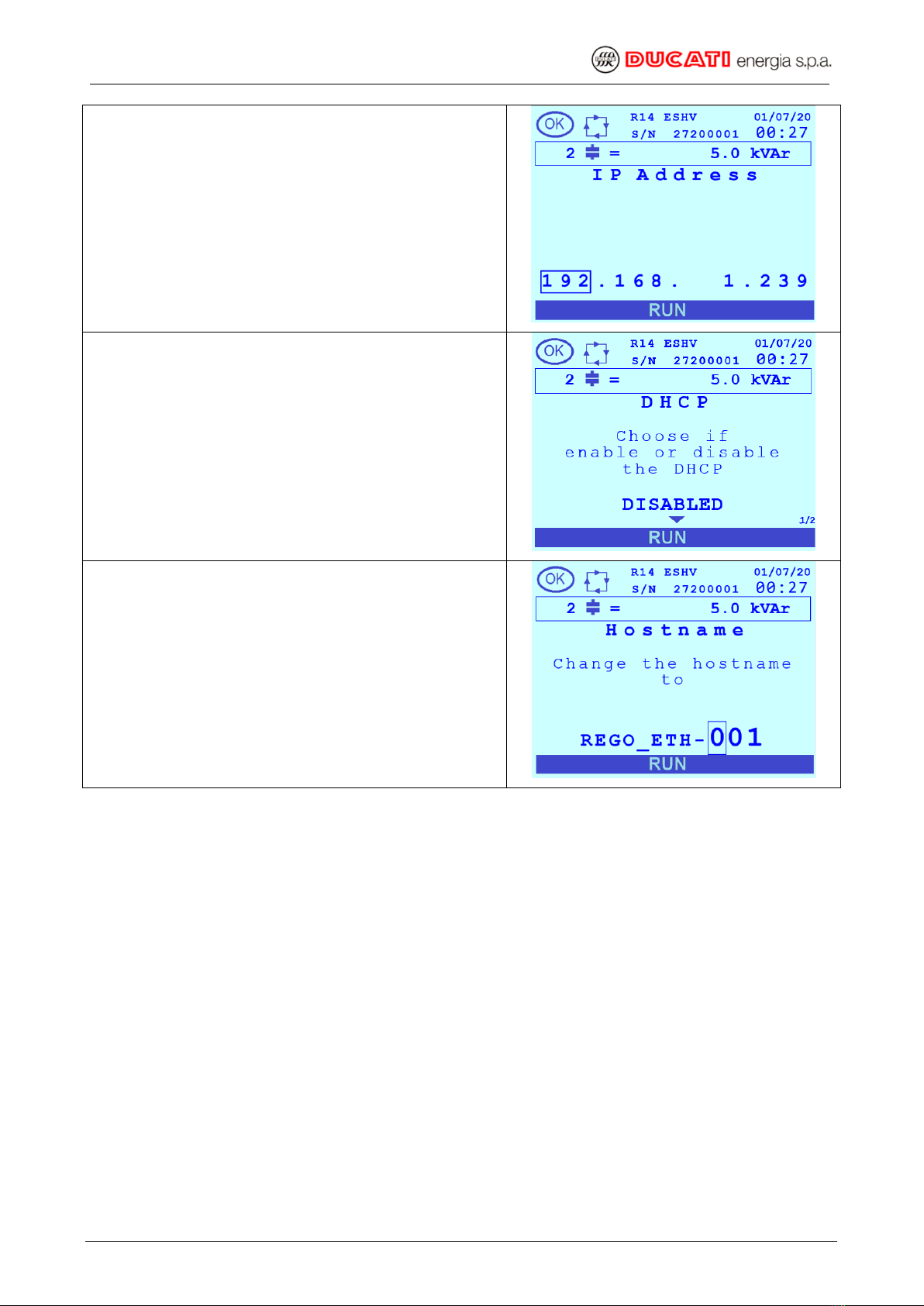
2.1 DEFAULT SETTINGS
The default settings of the instrument are as follows:
DHCP = Disabled
IP address = 192.168.1.239
Hostname = REGO_ETH-001
2.2 INSTRUMENT CONFIGURATION
To configure the instrument for the first time, you can alternatively proceed in one of the
following ways:
1. Enable the DHCP from the setup menu of the instrument, connect the R14 to the Ethernet
network and then, from a PC also connected to the network, access the device with any
browser (Internet Explorer, Mozilla Firefox, etc.) typing http://REGO_ETH-001 (default
Host name
i
). At this point is possible to change appropriately all the configuration
parameters. Should the Host name be not available, read from the setup menu of the
instrument the IP address assigned (page “IP Address” of the menu “Ethernet”) and use it
to access.
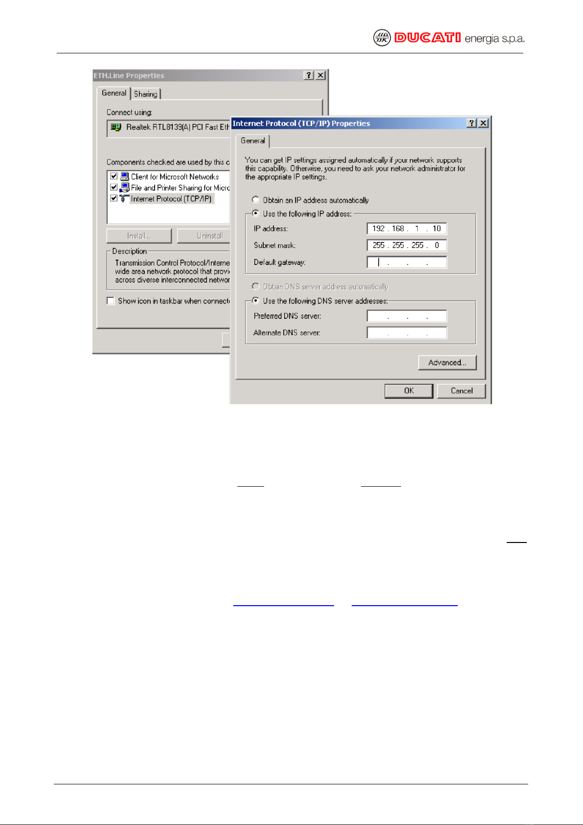
2. First configure the PC with an IP = 192.168.1.xxx, with xxx other than 239, and with
Subnet Mask = 255.255.255.0. To do this start from Settings → Control Panel → Network
Connections → Local Area Connection (LAN) → Properties → Internet Protocol (TCP / IP)
(Properties), select “Use the following IP address” and set IP and Subnet mask with the
previous mentioned parameters (see next picture for more details). Then press “OK” and
confirm all the settings, then restart the PC to activate any changes made
i
The access to the instrument through its Host name will be possible only if the NetBios service is enabled.

PFC R14 Ethernet User Manual
FileName: Man_Ethernet_Eng_R14_v0rB.doc Pag. 10 di 30
Picture 1 –PC network configuration
Afterwards, still leaving the DHCP of the instrument disabled, alternatively proceed as
follows:
Connect the PC directly to the R14 using a network cable
Alternatively, connect the PC directly to the Ethernet network. This option is only
possible if there aren’t already present on the network other devices with IP address
192.168.1.239 and = 192.168.1.xxx (where xxx = address previously set on the PC)
After that, it will be possible to access the instrument via any browser (Internet Explorer,
Mozilla Firefox, etc.) typing http://192.168.1.239 or http://REGO_ETH-001i. At this point
it’s possible to change the various configuration parameters appropriately.
NOTE: if you have problems opening the Web page, check that the proxy server should be
disabled.

PFC R14 Ethernet User Manual
FileName: Man_Ethernet_Eng_R14_v0rB.doc Pag. 11 di 30
3. WEBSERVER
The instrument has an internal Web server, making available to the user some pages of
visualisation and configuration. In this way the Web server makes available a virtual instrument
on the remote user’s PC. Is possible to access the device via any browser (Internet Explorer,
Mozilla Firefox, etc.) typing http://instrument-IP-address or http://instrument-host-namei.
The first page available in the list is the STATUS PAGE, where all outputs states and Cosphi
value are displayed.
Figure 1: Status page

PFC R14 Ethernet User Manual
FileName: Man_Ethernet_Eng_R14_v0rB.doc Pag. 12 di 30
After logging the device, the first page displayed will be the following (menu PFC R14):
Picture 2 –First visualisation page
Browse the visualization pages by
clicking on the virtual instrument
keys, in the same way used as on
the real instrument.

PFC R14 Ethernet User Manual
FileName: Man_Ethernet_Eng_R14_v0rB.doc Pag. 13 di 30
The MEASURES menu located in the top left allows to display some of the measured values
shown in tabular format.
Picture 3 –Measures summary table

PFC R14 Ethernet User Manual
FileName: Man_Ethernet_Eng_R14_v0rB.doc Pag. 14 di 30
The PARAMETERS menu located in the top left allows to display some of the parameter values
shown in tabular format.
Picture 4 –Parameter summary table

PFC R14 Ethernet User Manual
FileName: Man_Ethernet_Eng_R14_v0rB.doc Pag. 15 di 30
The ALARMS menu located in the top left allows to display the alarms status.
Picture 5 –Alarms summary table

PFC R14 Ethernet User Manual
FileName: Man_Ethernet_Eng_R14_v0rB.doc Pag. 16 di 30
The STATISTICS menu located in the top left allows to display some of the statistic values
shown in tabular format.
Picture 6 –Statistics table

PFC R14 Ethernet User Manual
FileName: Man_Ethernet_Eng_R14_v0rB.doc Pag. 17 di 30
The DAILY GRAPHS menu allows to display the histogram with the value of Cosphi, PF and dkVAr
of the last 30 days. The plus or minus sign (capacitive or inductive value) is defined by the color of
the bar, as per the legend in the top right of the screen.
Figure 2: Daily graphs - drop down menu
The measured value initially displayed is the Cosphi; you can switch to PF and dkVAr by clicking on
the drop-down menu.

PFC R14 Ethernet User Manual
FileName: Man_Ethernet_Eng_R14_v0rB.doc Pag. 18 di 30
By clicking on a specific bar it is possible to check the exact value of the quantity, preceded by the
date.
Figure 3: daily graphs - punctual values

PFC R14 Ethernet User Manual
FileName: Man_Ethernet_Eng_R14_v0rB.doc Pag. 19 di 30
The MONTHLY GRAPHS menu is very similar to the Daily graphs menu and shows the average
values of the last 12 months of Cosphi, PF and dkVAR. Again, the plus or minus signs (capacitive or
inductive values) is defined by the color of the bar as per legend in the top right of the screen.
Please refer to previous paragraph to understand how to select the different variables or how to
show the exact value of a quantity in a particular month.

PFC R14 Ethernet User Manual
FileName: Man_Ethernet_Eng_R14_v0rB.doc Pag. 20 di 30
The HARMONICS menu located in the top left allows to display the voltage and the current
harmonic values shown in tabular format.
Picture 7 –Harmonics summary table
Table of contents