DUCATIHOME CTH48 2.0 User manual

z
CTH48 2.0
Electronic board for 12V dc swinging gate openers
Wiring and settings manual
www.ducatihome.it

Electronic board model CTH48 2.0 for swinging gate opener
2
Table of Contents
Resume of CTH48 features ........................................................................................................................page 3
Quick stat guide........................................................................................................................................page.4-5
Label with resume of wiring diagrams.......................................................................................................page 5
Important safety instructions.......................................................................................................................page 6
CTH48 2.0 Technical data...........................................................................................................................page 7
CONTROL UNIT.........................................................................................................................................page 8
PREPARATIONS.......................................................................................................................................page.8
WALL FIXING OF THE CONTROL UNIT .................................................................................................page 8
EXAMPLE OF INSTALLATION ON A 2 SWINGING WINGS GATE ........................................................page 8
Power supply: by AC 230V or 110V mains ............................................................................................. page 9
Backup battery Power supply....................................................................................................................pag.10
Solar panel + battery Power supply...........................................................................................................page 11
SOLAR PANEL INSTALLATION ...............................................................................................................page12
CTH48 2.8 WIRINGS DIAGRAM.............................................................................................................. page 13
CTH48 2.8 WIRINGS............................................................................................................................... page 14
POTENTIOMETER: T1 = TIME: TO SET THE OPERATING MODE.......................................................page 15
POTENTIOMETER: T2 = POWER: TO SET THE MOTOR POWER......................................................,,page 15
POTENTIOMETER: T3 = SOFT STOP: TO SET THE SOFT STOP PHASE........................................... page 15
PUSH BUTTONS:P1; P2; P3.................................................................................................................... page 16
SETTING: Adjustment of the phase shift time between the 2 leaves during the closing manoeuvre ........page 17
SETTING: Adjustment of the working time of the pedestrian opening...................................................... page 17
meaning of warning lights through LED lights .......................................................................................... page 17
RADIO REMOTE CONTROLS.................................................................................................................. page 18
WIRED COMMAND TO OPEN YOUR GATE ( FULL OPENING / PEDESTRIAN OPENING).................page 19
SPECIAL ANTI-WIND MANEUVER...........................................................................................................page 19
WIRED COMMAND TO STOP YOUR GATE ( EMERGENCY STOP)......................................................page 20
SAFETY PHOTOCELLS ............................................................................................................................page 20
Wirings of photocells model laser100B/Key100B/ KOL450B/750B............................................................page 21
Wirings of photocells model laser100B/Key100B/ KOL450B/750B............................................................page 22
Wirings of photocells model SW7120 and LASER7120.............................................................................page 23
Electric lock ...............................................................................................................................................page 24
CE certicates.............................................................................................................................................page 25
Manufacturer’s limited warranty conditions.................................................................................................page 26
Testing and commisioning of the automation .............................................................................................page 27

Electronic board model CTH48 2.0 for swinging gate opener
3
CTH48 2.0 Feartures:
Super Energy Saving System: only 0,007A stand-by consumption
1) Available in 2 versions: 12V or 24V:
12V can manage 12V dc actuators to operate 1 or 2 leaf swinging gates thrust up to 1200N/120W
24V can manage 24V dc actuators to operate 1 or 2 leaf swinging gates thrust up to 2400N/240W
2) Can work by 3 types of power supply:
mains power supply AC110-230V 50-60HZ
mains AC power supply + BACK up battery in case of power failure
battery and solar panels for 100% autonomous use
3) 3 types od commands availables
Full Opening
Pedestrian opening (adjustable)
Emergency STOP
4) Ducati rolling code radio receiver on-board 2 channels
1 channel to memorize remote control button to operate full maneuver
1 channel to memorize remote control button to operate pedestrial access partial maneuver
5) Working mode
Step-by-step
Automatic closure (adjustable timing)
Semi-automatic closure (adjustable timing)
6) Outputs for:
Blinking light; Courtesy timed lighting or gate status signal; electrick lock
7) Safety:
ARS system: automatic reverse on obstacle detection in compliance with UE EN12453-2017
Emergency beam/ infrared safety sensors/ photocells NC input
8) End Limits:
Automatic pressure detection
9) Soft Stop
high speed ( 1,5-2cm/sec) with deceleration at the end of the stroke for soft approach of the leaf
10) Motor power adjustment
can increase or decrease motor power and sensitiveness on detecting an obstacle.
11) Gates wings lag time adjustment in closing
adjustable time lag between starting
12) Electric lock function
closing maneuver with extra push to trigger the electric lock even on very long gates
13) Strong wind maneuver
maneuver command in windy situation

Electronic board model CTH48 2.0 for swinging gate opener
4
QUICK START GUIDE
TIME POWER SLOW
ON
OFF
1
ON
OFF
ON
OFF
6
ON
OFF
ON
OFF
5
ON
OFF
ON
OFF
4
ON
OFF
ON
OFF
3
ON
OFF
ON
OFF
2
ON
OFF
mechanical end limit to stop the gate
Install actuators and open the gate
M1 M2
Blu
Blu
Marrone
Marrone
M1 M2
Blue
Blue
Brown
Brown
M1 M2
Blu
Blu
Marrone
Marrone
M1 M2
Blue
Blue
Brown
brown
TIME POWER SLOW
pull-to-open push-to-open
WARNING! BEFORE TO START MAKE SURE THAT:
A- Actuators must have already been mechanically installedon the gate (see actuator’s installa-
tion instructions)
B- Attention: the gate leaves must stop on a mechanical stop Make sure that the gate structu-
re has mechanical limit stops xed to the ground to stop the gate leaves both in the open and
cloded gate position.
Alternatively, where provided, make sure that the actuator model in use has a mechanical end
limits stop built into the actuator and check that the stop is correctly adjusted to stop each gate
leaf in the correct end position.
C- The gate must be in the fully OPEN gate position
D- actuators must be locked
1°) make sure that potentiometers are in following positions:
- T1 potentiometer (TIME) is fully turned counterclockwise
- T2 potentiometer (POWER ) is fully turned clockwise
- T1 potentiometer (SLOW/SOFT STOP) is turned +30° clockwise
2°) make sure that deep switches are in the following positions:
- switch n° 1 in ON position for 2 wings gate / in OFF position for 1 wing gate
- switch n° 2 in ON position
- switch n° 3 in ON position
- switch n° 4 in ON position
- switch n° 5 in ON position
- switch n° 6 in OFF position
3°) Wire the motor cables to the board respecting cable polatity:
M1= actuator installed on gate leaf that opens rst
M2= actuator installed on gate leaf that opens as second
Polarity for gates opening towards inside ( pull-to-open)
13= M1 blue cable
15= M1 brown cable
16= M2 blue cable
17= M2 brown cable
Polarity for gates opening towards outside ( push-to-open)
13= M1 brown cable
15= M1 blue cable
16= M2 brown cable
17= M2 blue cable
4°-A) FOR Openers powered by mains AC power supply:
4°-A-1) Remove the fuse upstream of the AC 110/230V 5x20 1.2AT transformer from the fuse holder
4°-A-2) Connect the mains AC power supply cables to the AC terminal block
4°-A-3) Insert the previously removed fuse on the fuse holder
4°-A-4) The gate wings will close until the gate is closed
toroidal
transformer
Protection
fuse
main AC power
supply
230-110V/50-60Hz
4°-B) For 12V openers powered by battery and solar panel:
On 12V electronic boards (CTH48 2.0):
4°-B-1) Check the battery voltage and make sure battery is fully charged.
Warning. Use only lead-acid battery 12V min. 7A
4°-B-2) Wire the battery to the board by the 2 wires (blue /red cables that are welded on CTH48 2.0
electronic board).
Warning! Respect battery wiring polarity: red cable= += positive / blue cable= - = negative
4°-B-3) as the board is powered the opener starts closure maneuver until the gate is closed reaching
the mechanical end limit.
Now your gate opener is ready to operate!
Push the top left button on your remote control-FOB to command a new maneuver: the gate will
open. Note: remote controls that are supplied in a kit are already memorized on the electronic board
In case you need to memorize a new remote control follow instructions described further in this
manual.
Check that the gate starts by high speed, slow down before reaching the mechanical end limit and
stops after the gate leaf has reached the mechanical end limit installe don the ground. Push again
on remote control to close the gate before adding any further accessory as solar panel; key switch,
blinker or safety photocells and/or edit settings described further in this manual
On 12V boards: from
transformer to CTh48
2.0 board wire
black+ yellow cables
On 24V boards: from
transformer to CTh48
2.0 board wire
black+red cables
-+
-
-+
-
-+
CTH48 2.0
(12V)
lead acid 12Vdc battery
blue cable =negative -
red cable = positive +
solar panel 12V min10W
max 20W solar panel
n°11 =negative -
n°12 = positive +
CTH48 2.0
(12V)

Electronic board model CTH48 2.0 for swinging gate opener
5
FUSE
FTC
(NC)
CTH48
M1 M2
STOP
-+
Fuse10AT
5 x 20
TIME POWER SLOW
12V dc**
output
Blu
Blu
Marrone
Marrone
12V** dc
P1 P2 P3
switch
230V 50-60Hz
110V 50-60Hz
100
0
-+
T1 T2 T3
8sec
sec
25
12V yellow
Start PEDSTART
Start NO
comune
Start pedonale NO
Fotocelliule NC
comune
Sopp emergenza NC
Positivo + 12V
Negativo - 12V
SOLAR - negativo
SOLAR - positivo
0 black
56
-
FUSE
FTC
(NC) 12V** 10W
M1 M2
-
+
protection fuse
10AT
5 x 20
TIME POWER SLOW
Blue
Blue
Brown
Brown
P1 P2 P3
switch
+-
100
0
-+
T1 T2 T3
8sec
sec
25
protection fuse
0,8 AT 5 x 20
Start (full) NO
Ground (COM)
Start (pedestrian) NO
photocells NC
Ground (COM)
emergency STOP NC
Positive output + 12V
Negative output - 12V
SOLAR - negative
SOLAR + positive
56
T1 = TIME
0 = step-by-step working mode; turn clockwise
to set timerized automatic closing working mode.
pause time up to 100 seconds
T2= POWER
turn clockwise to increase motor power
and to reduce obstacle detection sensitivity
T3= SOFT STOP
turn clockwise to postpone the
deceleration starting point
and vice versa
button to memorize a remote
control button to be used for total
maneuver
aereal
antenna
ON
OFF
1
ON
OFF
1
ON
OFF
2
ON
Full
Semi
ON
OFF
3
ON
OFF
4
ON
OFF
4
STOP
STOP
garden light
ON
OFF
5
ON
status light standard
ON
OFF
6
M1 fast
close
Ducati Home automation
via cassani snc
43036 Fidenza (PR) Italia
+39-0524-527967
+39-335-1022019
www.ducatihome.it
Electronic board model
CTH48 2.0
MANUAL
Electrical connections
1Ground aereal antenna
2Antenna Cable
3/4 START NO clean contact to command the start of a total maneuver cycle.
The contact must be closed for 1 second to start the manoeuvre.
4/5 START PEDESTRIAN NO clean contact to command the start of a pedestrian maneuver
cycle ( only M1 will open/close)
6/7 SAFETY INFRARED PHOTOCELLS SENSORS = NC clean contact
7/8 EMERGENCY STOP = NC clean contact (if the contact is open the gate will stop work)
9 + 12V dc positive services power supply output (24V in case of 24V version board)
10 - 12V dc negative services power supply output (24V in case of 24V version board)
11 - 12V dc solar panel input negative.
12 + 12V dc solar panel input positive.
Warning: respect the solar panel wiring polarity! Warning: in case of a 24V version board, it is
mandatory to add the #CMBAT2.0/24 charger, 2 x 12 panels will be connected in series and
the panel input will be 24V
13 motor M1 blue cable (M1= motor on leaf that opens rst)
14 motor M1 brown cable (M1= motor on leaf that opens rst)
15 motor M2 blue cable (M2= motor on leaf that opens as second)
16 motor M2 brown cable (M2= motor on leaf that opens as second)
WARNING: if used on a 1-leaf gate, connect the single motor as M1
17/18 Choice of 2 functions available:
A) with switch n° 6 in the “ON” position, terminals 17/18 have the function of timed courtesy
light output (see instruction manual for detailed wiring diagram).
B) with switch n° 6 in the “OFF” position, terminals 17/18 have the function of the gate status
light output use a 12V max 10W LED lamp (see instruction manual for detailed wiring diagram).
19+/20- 12V dc electric lock output (19 positive/ 20 negative) WARNING!
compatible only with 12V/dc power supply electric locks or ac electric locks equipped with
booster module to convert dc current into ac current
21/22 flashing light output 12V max 10W (the output becomes 24V d c on 24V version boards)
Output cables for direct connection to the 12V dc battery:
Red wire = positive(+);
Blue wire = negative (-)
Warning: for 24V electronic board ( CTH48 2.0/24V) use a CMBAT 2.0/24V charger and wire
2 x 12V batteries in series to the CMBAT charger. Then wire the CMBAT to the CTH48 2.0/24V
WARNING: respect the wiring polarity!
Reversing battery or solar panel polarity causes immediate breakdown
of the electronic board and this type of damage is not covered by the manufacturer’s limited
warranty.
WWW
Toroidal transformer 105VA
button to enter mode
pedestrian opening time adjustment e
time shift ante
New 2023!
12V
24V
version
version
M1 = motor on leaf that opens rst
M2 = motor on leaf that opens as second
Warning: the shown motor cabl epolarity is
valid for gates that opens towards inside the
property ( PULL-TO-OPEN) in case of a gate
that opens outwards (PUSH-TO-OPEN) the
polarity of the motor cables (brown and blue)
must be reversed
Rev 04.23/ENG
button to memorize a remote
control button to be used for a
pedestian maneuver
Warning:
wires from toroidal transformer:
0 = black cable
12V = yellow cable
24V= red cable
use black + yellow for 12V
use black + Yellow for 24V
12V** solar panel
power input
blue
red
12V min. 7A
Lead/gel battery
WARNING !
for 24V board versions an
additional #CMBAT 2.0/24
battey charger is required
use 2 x 12V batteries in
series connected and
wire them to the CMBAT
2.0/24V charger. Then wire
the “to board” output form
CMBAT 2.0/24V to the
blue and red cables of the
CTH48 2.0/24V board.
WARNING !
Respect the wiring
polarity!
red= positive+
blue= negative -
** = 24V dc for 24V electro-
nic board #CTH48 2.0/24V
Label with quick wiring diagram
to cutt-out and apply on the back of your control box unit cover
back-up battery and
solar panel charge
are available for
12V version. while
electronic board in 24V
version is intend to be
powered by mains AC
power supply.

Electronic board model CTH48 2.0 for swinging gate opener
6
Important safety instructions.
Follow all instructions, as incorrect installation can lead to serious injury.
WARNING: Before proceeding, read and understand the general warnings for the user.
The product must be destined only for the use for which it was expressly designed and any other use is to be considered
dangerous. • The manufacturer cannot be held responsible for any damage caused by improper, incorrect or unreasonable
use. • The product in question is expressly designed to be assembled on partly completed machinery and/or equipment for
the purpose of building a machine governed by the Machinery Directive 2006/42/EC. • The nal installation must comply
with the Machinery Directive 2006/42/EC and with the European reference standards in force. • The manufacturer declines
all responsibility for the use of non-original products; this also implies the forfeiture of the guarantee. • All the operations
indicated in this manual must be carried out exclusively by expert and qualied personnel and in full compliance with the
regulations in force and on a structure built in a workmanlike manner and perfectly compliant with the regulations in force in
the area. The structure on which the product will be installed must have a certicate of safety and compliance with the regu-
lations in force in the area. • The preparation of the cables, the installation, the connection and the testing must be carried
out observing the rule of the art, in compliance with the standards and laws in force. • During all installation phases, make
sure you operate without voltage. • All the components (e.g. actuators, photocells, sensitive edges, etc.) necessary for the
conformity of the nal installation in accordance with the Machinery Directive 2006/42/EC and the reference harmonized te-
chnical standards Verify that the indicated temperature range is suitable for the place of installation. • Make sure that, in the
place foreseen for installation, the product is not wetted by direct jets of water (irrigators, pressure washers, etc.). • Provide
an adequate disconnect device in the power supply network and in accordance with the installation rules.
• Adequately delimit the entire site to prevent access by unauthorized persons, especially minors and children. • It is recom-
mended to use suitable protections to avoid possible mechanical dangers due to the presence of people within the range
of action of the automation. • Electric cables must pass through suitable pipes, ducts and cable glands in order to guaran-
tee adequate protection against mechanical damage.
• Electric cables must not come into contact with parts that can heat up during use (for example: motor and transformer). •
Before proceeding with the installation, check that the guided part is in good mechanical condition, and that it opens and
closes correctly. • The product may not be used to automate a guided section including a wicket door, unless the drive can
only be activated with the wicket door in the safe position. • Ensure that entrapment between the driven part and surroun-
ding xed parts by movement of the driven part is prevented. • All xed controls must be clearly visible after installation, in
a position where the driven part is directly visible, yet away from moving parts. In the case of a maintained action command,
this must be installed at a minimum height of 1.5 m from the ground and must not be accessible to the public. • If not alre-
ady present, apply a permanent label describing how to use the manual release mechanism near its operating element. •
Make sure that the automation has been properly adjusted and that the safety and protection devices, as well as the manual
release, work correctly. • Before delivering to the user, check the conformity of the system with the harmonized standards
and with the essential requirements in the Machinery Directive 2006/42/EC. • Any residual risks must be signaled using
suitable pictograms positioned clearly in view and must be explained to the end user. • Position the identication plate of
the machine in full view upon completion of the installation. • If the power cable is damaged, it must be replaced by the
manufacturer or by the authorized technical assistance service, or in any case by duly qualied personnel, to avoid any risk.
• Keep this manual in the technical le together with the manuals of the other devices used to build the automation system.
• It is recommended to deliver all the user manuals relating to the products that make up the nal machine to the end user.
• In the event of product malfunction, stop using it and contact customer service at https://www.ducatihome.it or at the
telephone number indicated on the website
DISPOSAL OF THE PACKAGING
The packaging components (cardboard, plastics, etc.) are similar to solid urban waste and can be disposed of without
no difculty, simply by carrying out the separate collection for recycling.
Before proceeding, it is always advisable to check the speci c regulations in force in the place of installation.
DO NOT DISPOSE IN THE ENVIRONMENT!
DISPOSAL OF THE PRODUCT
Our products are made from different materials. Most of them (aluminum, plastic, iron, electrical cables) are
comparable to municipal solid waste. They can be recycled through collection and separate disposal in the centres
authorised.
Other components (electronic boards, transmitter batteries, etc.) may instead contain polluting substances.
They must then be removed and handed over to companies authorized to recover and dispose of them.
Before proceeding, it is always advisable to check the speci c regulations in force in the place of disposal.
DO NOT DISPOSE IN THE ENVIRONMENT!

Electronic board model CTH48 2.0 for swinging gate opener
7
Technical data and features
CTH48 2.0
(equips the KONTROL 9048 2.0 control unit)
Use made to manage 12V dc actuators to automate a swinging gate with 1 or 2 leaves
Mains AC Power supply
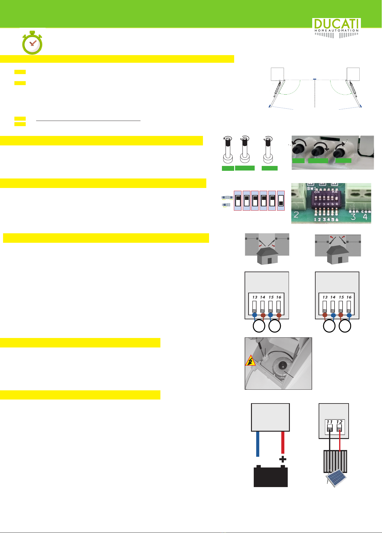
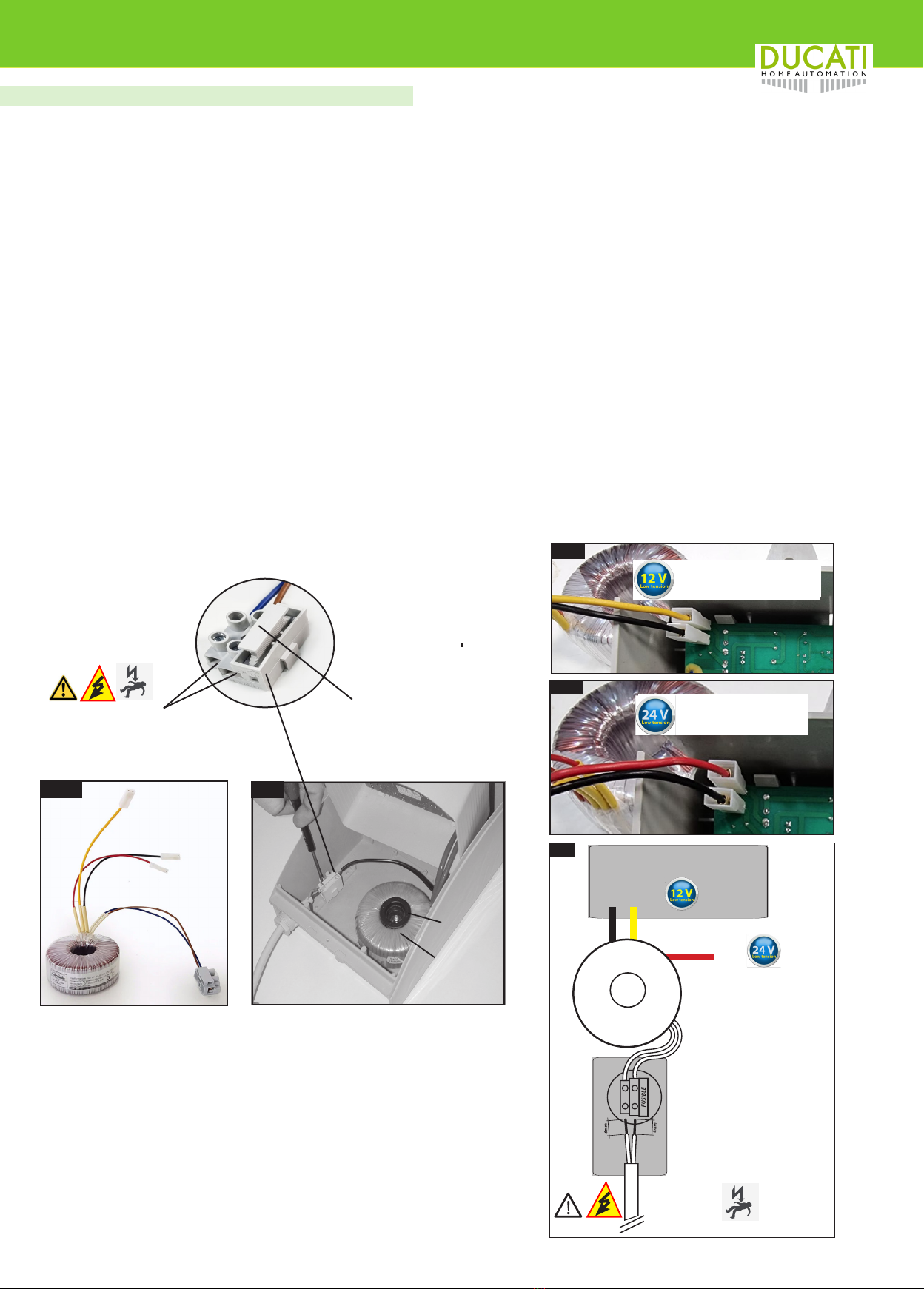
√12V ac/dc by means of a toroidal transformer 105W input AC 230V 50/60Hz or AC110V 50/60Hz transformer output 12Vac (yellow+ black cable). A rectifier on
the board transforms the AC current into DC current. Warning: for optimal performance it is recommended to always keep a backup battery battery wired to
the system
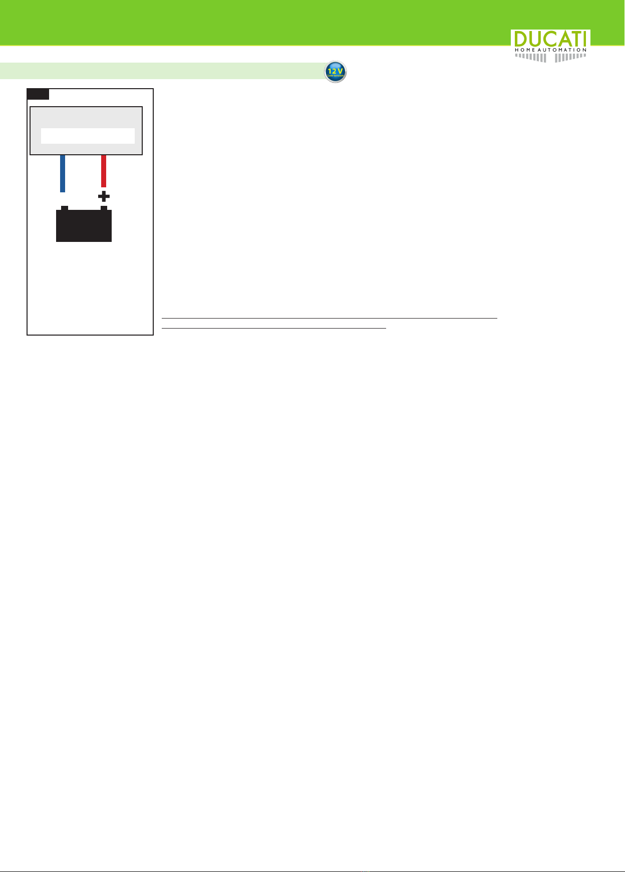
power supply from emergency battery for
autonomous use during main AC power
supplu power failure (black-out)
√. we recommend the use of a 12V 7A or 12V 12A lead- acid battery which can be housed inside the compartment of the control box unit
(CTh48 is ompatible with commercial batteries) The 12V battery charger management system is integrated on board
Power supply by battery and solar panel
√. 12V max 20W solar panel can be wired directly to the electronic board input connecotors. The battery will be automatically recharges rby the 12V 10W or 20W
solar panel (on-board battey charger management). The solar panel autonomously recharges the back-up battery (12V min.7A) and do not require any wiring to the
mains AC power supply. Provides 100% autonomous use from renewable energetical sources, protecting the environment and savings on bills
stand-by absorption 0,008A
Anti-crushing safety system √ Obstacle detection safety system in compliance with the EU EN12453. 2017 norms.
Radio receiver √ Ducati rolling coded radio revceiver wuth 2 radio receiver channles: 1channel to store a remote control button that commands the full manoeuvre. 1 channel to
store a remote control button to comman the pedestrian opening maneuvre. compatible with any Ducati rolling code radio remote control
Internal memory capacity for storing remote
controls
Maximal storage capacity= 48 buttons. They can be stored indifferently on the 1st or 2nd radio reception channel. AAttention: memory position means 1 occupied
position for each memorized button of a remote control
SOFT STOP soft approach of the door
at low speed √. Always active. both opening and closing. during travel at low speed the blue LED remains lit
Reverse direction in case of contact
with an obstacle
√. during the initial phase of the manoeuvre, at high speed, in the event of contact with an obstacle, the gate reverses the direction of travel. during the final phase
of the low speed maneuver (SOFT STOP) in case of contact with an obstacle, the gate stops.
Pedestrian opening cycle
(partial opening of only 1 door)
to allow pedestrians transit only)
√. It can be controlled both by radio control and by wired control (e.g. key switch, intercom button or similar)
Compatibility with use of electric lock √. electric lock power output: 12V dc. compatible with 12V DC electic locks or 12V AC electric locks with booster module (transforms dc current into ac current).
Compatibility with the use of safety photo-
cells √. NC contact input (normally closed) the photocells are active during the closing cycle and produce the immediate reopening of the gate
Compatible with the use of a button for
an emergency TOTAL STOP √. NC contact input (normally closed) the emergency stop contact stops the gate and disables any function for the entire time the contact remains open.
Compatible with the use of a timed courtesy
light
√ courtesy light power output 12V max 10W. The light will automatically turn on when the gate starts and will remain on for 40 seconds after the end of the manoeu-
vre. It is also possible to connect courtesy lights with 230V power supply using a power relay and the appropriate diagram
Compatible with the use of a remote light that
signals the status of the gate √
Compatible with the use of wired control
systems such as key switch / push button/
GSM command/Wifi command to operate
total
√it is possible to connect in wire (use a bipolar cable min. 0.3mm2) control devices for starting the gate operation such as, for example, key switch, button, intercom
button, control devices with Wi-fi system, GSM. Attention: clean contact input normally open. to command the start of the maneuver cycle the contact must be closed
for 1 second only
anti-wind man-operate command
√. by keeping the START contact closed with the hold-to-run command, the forced maneuver is commanded with maximum motor power and without anti-obstacle
amperometric control. This maneuver is only permitted with a man present who watches over the gate during the entire maneuver and aimed at concluding the ma-
neuver in conditions of strong gusts of wind
AVAILABLE ADJUSYTMENTS
Motor power adjustment during SOFT STOP
(final part of the maneuver at low speed)
it is possible to increase or decrease the thrust force by rotating the potentiometer T2. In this way you can set the sentsitiveness in the event of an impact on an
obstacle to comply with the anti-crushing EU norms. This adjustment affects the low speed stroke ( SOFT STOP) which must correspond to the area of greatest risk
of crushing foreseen by the EN12453- standards
Adjustment of the starting point of the SOFT
STOP phase (deceleration)
It is possible to advance or postpone the beginning of the low speed maneuvering phase (SOFT STOP) by rotating potentiometer P3 in order to adapt the maneuver
to the individual system. The slowdown occurs at least 8 seconds after the start of the maneuver and can be postponed up to max. 25 seconds from the start of the
manoeuvre. The SOFT STOP function intervenes both in opening and closing. Pay attention that the slowdown occurs at the points where the regulation requires
carrying out pressure tests with a specific dynamometer to certify the system in compliance with the EN12453-2017 norms
Gate wings lag time adjustment during in
closing, to adjust the delay between M2 and
M1 start in closure maneuver (only for gates
with 2 swing leaves)
The phase shift between the start of motor M1 and M2 during opening is fixed. the phase shift of the leaves during closing is set by default and is adjustable with a
range from 0 to 30 seconds.
Adjustment of the width of the pedestrian
opening manoeuvre (timed adjustment)
Pedestrian opening is a time-controlled manoeuvre. by default the M1 leaf will open for 4 seconds. during this time it will be able to make a variable opening angle
depending on the structure and the fixing position of the actuators. However, it is possible to manage and adjust the working time during pedestrian maneuvering as
desired in order to open the M1 leaf with more or less degrees. The maximum time that can be set is 26 seconds.
WORKING MODE
Step by step √ lin step-by-step mode the impulses given by the radio control or by the wired device, both for the total maneuver and for the pedestrian manoeuvre, produce the
following sequence: 1 impulse opens, 1 impulse during the movement stops, 1 impulse closes
FULL AUTOMATIC closing
√ In FULL-automatic closing mode, the impulses given by the radio control or wired device, to control the total manoeuvre, produce the following sequence:
1 impulse opens until the door reaches the mechanical end stop, it remains open and counts the set pause time (max. 100 sec.) then it closes automatically. During
opening and pause time, it does not accept further commands, during closing a further impulse reopens the gate
Attention for the pedestrian maneuver cycle: it is not possible to interrupt the movement either during opening or closing... the door opens, reaches the stop, stops,
counts the time and then closes automatically after the set pause time (from 1 to 100 sec)
SEMI-AUTOMATIC closing
√ In SEMI-automatic closing mode, the impulses given by the radio control or wired device, to control the total manoeuvre, produce the following sequence:
1 impulse opens until the door reaches the mechanical end stop, gate remains open and counts the set pause time (max. 100 sec.) then it automatically closes. Both
during opening as during the open pause, a command causes the gate to close immediately, while during closing a further impulse reopens the gate. Attention for
the pedestrian maneuver cycle: it is not possible to interrupt the movement either during opening or closing. the door opens, reaches the stop, stops, counts the time
and then closes automatically after the set pause time (from 1 to 100 sec)
Model CTH48 2.0
Mains Power supply (V-50/60Hz) 230V -550/60Hz AC or 110V 50/60Hz AC check the the toroidal transformer in use
Motor power supply (V) 12V DC
Power supply to the electroni cbaord (V) 14-15 AC (form 105VA toroidal transformer)
Stand-by consumption (A) 0,008A
TWorking temperature(°C) -20°C / + 55°C
Cycles/hour 120
Consecutive cycles no limits
Average life (cycles)** 1.000.000
**The average life of the product is purely
indicative and estimated in consideration of
compliant conditions of use, installation and
maintenance. It is also inuenced by further
factors, such as climatic and environmental
conditions.
CTH48 2.0 technical data (standard 12V version)

Electronic board model CTH48 2.0 for swinging gate opener
8
CONTROL UNIT
The CTH48 2.0 board is housed in the #PLBOX 812 model container for external use which also offers a compartment for housing
a 12V lead-acid battery from 7A up to 12A
Inside the PLBOX 812 container, the board can be protected by the inner protective cover #PLBOX.
PREPARATIONS
Prepare insulated ducts for the passage of cables for the motors and accessories. Lay the system power cable (from the AC network and/or from the solar
panel depending on the system) up to the position where you intend to fix the control unit
Warning: the connection to the AC 230V network must only be carried out by specialized electrician technicians.
Do not connect the AC power yourself: Danger of DEATH!
In the case of a system powered by a solar panel where you also want to maintain the possibility of being fed from the AC mains, it is recommended to use
a switch upstream of the AC power input.
For the connection of the actuators it is recommended to use suitable junction boxes.
For gates with 2 swing leaves it is always necessary to prepare a suitable underground duct.
WIRING: for the connection of the actuators it is recommended to use a bipolar cable with a double external sheath of min. 1.5 sq mm
for accessories such as flashing light, key selector, other control switches, we recommend the use of a bipolar cable with a double external sheath of 0.3/0.5
mm2. For connection to photocells it is necessary to provide cables with a section of 0.3 mmq and more precisely a bipolar cable for the transmitter photocell
4-wire cable for the receiver photocell.
For the solar panel, a bipolar cable of min. 1.5 sq.mm is recommended if the panel is fixed at a maximum distance of 2m. in case of greater length, a cable
with a larger section proportional to the length of the wiring must be used in order to limit the electrical resistance and the dispersion of energy.
Warning: provide a power supply disconnect device that can be activated in the event of an emergency
Warning: the control unit and activation commands must be placed in a place and at a height from the ground, which does not allow access and use by
unauthorized third parties or minors.
WALL FIXING OF THE CONTROL UNIT
Fix the bottom of the PLBOX 812 container to the wall using suitable screws and dowels (not supplied)
It is advisable to seal any holes to prevent infiltration of water, humidity, dust and insects.
For the passage of wiring cables to the motors and other accessories it is necessary to drill the lower part of the PLBOX 812
It is recommended to use special cable glands or cable clamps (not supplied).
See fig. 1 complete “Kontrol 9048 2.0” control unit
120 mm
180 mm
290 mm
#Kontrol 9048 2.0
compleete control unit
1
electronic board
# CTH48 2.0 or
container
#PLBOX812 inner protection cover
#PLBOX
terminal block with pro-
tection fuse holder for AC
mains input
toroidal
transformer
xing cone with screw
1
34
8
7
6
5
2
2
9
9
9
9
EXAMPLE OF INSTALLATION ON A 2 SWINGING WINGS GATE
Mains AC power supply
SOLAR PANEL POWER SUPPLY
(battery power supply + 100% autonomous recharge by solar panel: does not require any wiring to the mains AC 110/230V network
1-complete control unit with CTH48 2.0 electronic board; 2- electromechanical actuators; 3-ashing light; 4-aereal antenna; 5-key switch or other wired device to command the opener;
6-Ducati Rolling code radioremote control; 7-radio keyboard; 8-Solar panel; 9-safety photocells; 10-battery.
Note: the diagram presents a hypothesis of a system with a series of accessories by way of example: this diagram does not refer to any exact and predetermined kit composition
10
1
2
230V AC-50/60Hz
110V AC-50/60Hz

Electronic board model CTH48 2.0 for swinging gate opener
9
Power supply: by AC 230V or 110V mains
The board can be powered by the mains AC power supply by the specific 105VA toroidal transformer.
The use of toroidal transformers with double insulation guarantees maximum reliability and safety from sudden changes in voltage and ESD and durability over
time. The toroidal transformer must be fixed to the base of the control unit container using the special cone and screw supplied.
TOROIDALTRANSFORMER : transformer can be supplied in 2 alternative version:
model TRAfor 110V 50-60Hz AC power supply or for 230V 50-60Hz AC power supply
input cable for AC mains AC 230V-110V 50Hz power supply wiring
output cables for electronic board power supply: where:
black wire= 0;
yellow wire = 12V ac*;
red wire = 24V ac*
CTH48 2.0: for 12V openers: power the board from the toroidal transformer using the black and yellow wires (12V* ac)
CTH48 2.0/24V: for 12V openers: power the board from the toroidal transformer using the black and yellow wires (24V* ac)
*= nominal values)
The power output cables from the transformer must be connected to the special male faston connectors located on the back of the electronic board. No
polarity to respected.
Warning! Safety Recommendation: danger to life. The connection of the 230V high voltage mains power supply (110V on request) must be only performed
by a certified electrician!
The power cable from the AC mains must be connected upstream of the toroidal transformer to the protection terminal block/fuse holder fixed to the base of
the PLBOX812 container, as shown in the following images #3 and #4
The power cable from the AC mains must be connected upstream of the toroidal transformer to the protection terminal block/fuse holder fixed to the base of
the PLBOX812 container, as shown in the following images #3 and #4
WARNING!
To avoid damage in transit, the transformer may be shipped not pre-installed in the control
bix
In such case it will be necessary to fix the transformer to the base of the #PLBOX 812
container using the appropriate support cone with relative screw.
The terminal block for th AC power input with it’s protection fuse must balso fixed to the
base of the same container as shown in Fig.3B.
Back of the electronic board
CTH48 2.0
0
Black
4
A.C.
Fuse holder
protection Fuse: 230V - 0,8AT
protection Fuse: 110V - 1,2AT
to the transformer
N
N
F
12V
24V
230V 50H /
(110V 60Hz)
Yellow
Red
Transformer
3 B
terminal block
toroidal
transformer
xing cone with
screw
3 A
Main AC power supply input
230V/110V 50/60Hz
4B
4B
24V transformer
output: black-red
12V transformer
output: black-yellow

Electronic board model CTH48 2.0 for swinging gate opener
10
The CTH48 2.0 (12V) board is designed to be powered mains ac power supply
+ by a12V lead-acid emergency battery to guarantee self-operating maneuver in the event of a power failure
/blackout from the AC network.
In the presence of AC mains power, battery recharging occurs automatically through the recharging system
integrated in the circuit of the CTH48 2.0 board.
In the event of a black-out, the use of a 12V 7A battery guarantees up to an average of 4 days of operating autonomy.
while with a 12V 12A battery, the operating autonomy extends up to 7 days
Use 12V lead/gel standard commercial batteries.
Standard commercial 12V batteries from 7A to 12A can be housed inside the #PLBOX 812 container of the control unit.
Larger capacity batteries may be used, but must be housed in a separate and suitable container.
Connect the battery to the electronic board using the cables with faston connectors soldered on the back of the board.
WARNING!
Output cables on the board are intend for wiring directly to a 12V dc battery:
red wire = positive(+);
blue wire = negative (-)
WARNING! respect the connection polarity!
Wiring the battery with inverted polarity causes the immediate breakage of the electronic board
and the damage is not covered by the manufacturer’s warranty.
12V min.7A
lead-acid battery
WARNING!
respect the con-
nection polarity!
red= positive
blue= negative -
-
-+
-
-+
red/blue cables
soldered on the board
CTH48 2.0
Backup battery Power supply (CTH48 2.0 12V)
CTH 48 2.0 (12V)
5

Electronic board model CTH48 2.0 for swinging gate opener
11
ABSORPTION
CALCULA-
TION
SWUINGING
GATE
stand-by
consumption
(Ah)
daily 24h
stand/by
consumption
(A)
average consumprion
for mcycle open+
close
(A)
hypothesis of cycles
performed in 1 day
(open+ close)
total daily c
onsumptio: standby
+ maneuver
hipotesis (A)
average A recharged
/ per hour by a 10W
12V solar panel
in medium light
conditions (Ah)
assumed hours
of light exposure
(seasonal aver
age)
Totale ricarica di
energia giorna
Total daily energy
recharge (A)
Balance between
consumption and
recharge (A)
ELECTRO-
NIC BOARD
CTH48 2.0
1 WING
0,008 0,19
0,012 60 0,91
0,3* 51,5 + 0,59
2 WINGS 0,024 50 1,39 + 0,11
Wiring the battery to the CTH48 2.0
Wire the positive pole of the battery to the red wire welded on the CTH48 2.0 electronic board.
Wire the negative pole of the battery to the blue wire welded on the CTH48 2.0 electronic board. See drawing n°7
Warning: Respect the wiring polarity. In the event of polarity inversion, the electronic board will result damaged and such damage
is not covered by the manufacturer’s limited warrnanty.
Warning: before usemake sure touse a fully charged 12V lead acid battery.
How to recharge a battery:
To charge the battery from an electrical socket, it is necessary to use a battery charger with charge control.
For preventive battery recharging, it is advisable to use the optional item #MP037 or any other battery charger suitable for lead-a-
cid batteries with charge control and 13.8V-14V power supply output.
It is also possible to charge the battery using the toroidal transformer ( see page 12) by connecting a cable with a plug for an
electrical outlet to the transformer input (terminal board with protective fuse holder) and the 12V transformer output cables (yellow
and black cables) to the male faston connectors present on the back of the board.
Connect the battery to the electronic board using the special red and blue connection cables soldered on the CTH48 2.0
Warning: Respect the connection polarity.
How to check the battery Voltage to ensure it is fully charged:
Once the battery has been charged it is recommanded to doublecheck the battery voltage by means o a voltimeter.
Two test shall be performerd: 1° measurement: battery witout absorption load; 2° measurement: battery with a load
A battery in perfect condition at full charge should have a voltave output measurement of 13-13.3V without any load absorption.
Battery efficiency should also be measured during absorption (workload during a manoeuvre). The voltage of a battery in good
charge conditions must never drop below 12,5V measured with a working load.
Below 12V with load, the battery is to be considered flat or almost-flat. At the 11.5V level, the battery must be considered dischar-
ged below the minimum acceptable level and recharged immediately. Batteries are components subject to natural wear and tear.
The decay can also be influenced by external factors. Warning: batteries should not always be kept at a high charge level even
when not in use Attention. the charge capacity of the batteries decreases with temperatures below freezing point. The batteries
are therefore not components covered by the manufacturer’s limited warrnanty. A battery that even measures an excellent level of
voltage when empty, and that with the load drops suddenly below 11 V, is to be considered exhausted and must be replaced with
a new one
-
-
+
SOLAR - negativo
SOLAR - positivo
-
-
+
SOLAR - negative
SOLAR + positive
Wiring the solar panel to the CTH48 2.0
It is recommanded to use a Solar panel 12V 10W or 12V 20W. It is also possible to connect two 10W solar panels in parallel.
Wire solar panel negative (-) wire to connector n° 11 of the CTH48 2.0 electronic board.
Wire solar panel positive (+) wire to connector n° 12 of the CTH48 2.0 electronic board.
Warning: Respect the wiring polarity! RED= POSITIVE= + BLUE/BLACK= NEGATIVE= -
Cable dimension: the use of a 0,5mmq cable is enough cor cable lenght up tio 2m. for longer cabling 1/1,5mmq cables are re-
commnded. while use 1,5mmq for longer cables.
The amount of recharge depends on 3 factors:
- hours of exposure to light
- light intensity.
- solar panel capacity (W)
Advice: by downloading applications on your smartphone that measure the light intensity and compare it according to the xing
position and inclination and orientation of the solar panel. A higher light intensity will result in a higher recharge of the battery.
The measurement of the Ampere (A) charged by the panel requires special instruments, but it is possible to estimate the Ampere
(A) recharged with a certain proportionality, by measuring the V output from the solar panel cables with a simple Voltimeter. In prin-
ciple, bear in mind that the output voltage corresponding to a minimum recharge of A is 15V-16V. In summer, in full sun, the voltage
measurable from a 10W soalr panel output easily exceeds 20V. The electronic board manages battery recharge automatically.
ATTENTION:
By increasing the power of the panel, a greater recharge is obtained for the same time of exposure to light.
it is possible to connect 2 solar panels in parallel to increase the total charge capacity.
Increasing the battery capacity increases the duration of autonomy in the event of adverse weather conditions, thus guaranteeing
greater autonomy even in the event of persistence of time with low brightness.
ATTENTION:It is not recommended to connect the solar panel and the 230V mains power supply at the same time, but it is also
possible to connect to the mains power supply by providing a switch so as to be able to use the AC power supply only to recharge
the battery or temporarily feed from the mains in if the climatic conditions do not ensure sufcient charging from the solar panel.
Solar panel + battery Power supply (CTH48 2.0 12V)
The table shows a hypothesis for calculating consumption and autonomy with 1 10W panel and 7A battery in winter weather conditions with average bri-
ghtness (assuming only 5 hours of non-intense light with a minimum recharge of 0.3A/h) . Even in similar conditions it is possible to carry out 50 maneuver
cycles per day with a positive energy balance, therefore without affecting the battery charge.
12V min.7A
lead-acid battery
WARNING!
respect the con-
nection polarity!
red= positive
blue= negative -
-
-+
-
-+
red/blue cables
soldered on the board
CTH48 2.0
CTH 48 2.0 (12V)
7
8

Electronic board model CTH48 2.0 for swinging gate opener
12
SOLAR PANEL INSTALLATION
The solar panel/s should face SOUTH and in a well-lit place.
Avoid shady areas, which signicantly reduce the load capacity.
Regularly clean the surface of the panel: the accumulation of dust or dirt generally reduces the charge capacity of the panel
Position the solar panel at a recommended distance of up to 10 m from the automation control unit. If the panel is to be installed at a greater distance, it will be
advisable to use a cable with a larger section to reduce the electrical resistance and the resulting loss of current.
Fix the panel to the wall or to another rigid support with the specific bracket supplied. The solar panel must face SOUTH.
Check that no obstacle casts shadow on the panel and that it is in full light.
Connect the panel to the electronic board paying attention to respect the polarity of the wiring.
MAP OF SOLAR RADIATION IN THE WORLD
the map shows the average hours of sunshine per year. the hours of sunshine also vary according to the seasons and local climatic conditions
Example of fixing bracket for the 10W solar 1012 panel (attention the supplied brackets may vary from the images shown below
Warning: Respect the wiring polarity. In the event of polarity inversion, the electronic board will result damaged and such damage is not covered by the ma-
nufacturer’s limited warrnanty. red cable= += positive blue/black cable= - = negative
Useful information on solar panel charge.
LUMEN:
Lumen is measures of the intensity of a lumi-
nous ux (Sun)
The greater the lumens of solar luminosity on
the panel, the greater the recharge of A sup-
plied to the batteries per unit of time.
LUX
The values of lux and lumen are closely con-
nected: in fact, lumens indicate the amount of
light emitted by a source, while lux determines
how much light is present on a given surface. A
single lux is equivalent to 1 lumen per square
metre.
Usegul tips: you can download on your smar-
tphoe an App that that allow you to check
how many lumens the panel receives in a given
position. This can be a useful tool for choosing
the ideal position and angle of the panel with
respect to the sun.
On average, a 12V 10W panel with good light
exposure is charged with a voltage between
17.6 and 22V.
With this voltage it is quite consistent to evalua-
te an effective recharge of 0.3-0.5Ah

Electronic board model CTH48 2.0 for swinging gate opener
13
12V min. 7A
Lead/gel battery
WARNING !
back-up battery and
solar panel charge are
available for 12V ver-
sion. while electronic
board in 24V version is
intend to be powered
by mains AC power
supply.
WARNING !
Respect the wiring
polarity!
red= positive+
blue= negative.
-
FUSE
FTC
(NC)
CTH48
M1 M2
STOP -
-
+
+
Fuse10AT
5 x 20
TIME POWER SLOW
12V dc**
output
Blu
Blu
Marrone
Marrone
12V** dc
P1 P2 P3
switch
100
0
-+
T1 T2 T3
8sec
sec
25
AC mains power input
through transformer
105VA toroidal (faston connectors on the
back of the board)
24Vred
Wiring diagram CTH48 2.0
START PED
START
Start NO
comune
Start pedonale NO
Fotocelliule NC
comune
Sopp emergenza NC
Positivo + 12V
Negativo - 12V
SOLAR - negativo
SOLAR - positivo
56
Switch n° 1:
- Set to “ON” (up) for use on a 2-leaf gate;
- Set to “OFF” (down) for use on a 1-leaf gate;
Switch n° 2:
this switch has effect only if the potentiometer T1 is turned
clockwise selecting the operating mode with automatic closing.
- Position to“ON” (up) to select FULL Automatic
closing mode;
-Position to “OFF” (down) to select SEMI-Automa-
tic closing mode
Switch n° 3:
- Set to “ON” (up) if infrared safety photocells are
not wired to the baord. With this switch in the ON
position, the NC contact is kept closed without the
need for a physical jumper between terminals 6-7.
- Set to “OFF” (down) if photocells are used and
wired to the photocell contact (NC) on terminals 6-7
Switch n° 4:
- Set to “ON” (up) if an emergency STOP button is
not wired to the baord. With this switch in the ON
position, the NC contact is kept closed without the
need for a physical jumper between terminals 7-8.
- Set to “OFF” (down) if an emergency STOP
button is used and wired to the STOP contact (NC)
on terminals 7-8
ON
OFF
3
ON
OFF
3
Switch n° 5:
- Set to “ON” (up) to select the timed courtesy/
garden light function from terminals 17/18*
- Set to “OFF” (down) to select the gate status
signaling light function from terminals 17/18
** (see specic wiring diagram further on this
manual)
Switch n° 6:
- Set to “ON” (up) to select the following function:
M1 closes at high speed without slowing down
(recommended if electric lock is present)
- Set to “OFF” (down) for standard operation, i.e.
both M1 and M2 both in opening and closing ma-
neuver will slow down before stop (both wings will
SOFT STOP in closure)
FUSE
FTC
(NC) 12V** dc
10W
M1 M2
STOP -
-
+
+
TIME POWER SLOW
Blue
Blue
Brown
brown
P1 P2 P3
switch
12V** Solar Panel
power input
+-
AC 230V 50-60Hz.
AC 110V 50-60Hz.
100
0
-+
T1 T2 T3
8sec
sec
25
12V yellow
Fuse: 230V - 0,8AT
Fuse: 110V - 1,2AT
Start NO
common/ground
Start pedestria NO
photocells contact NC
common/ground
emergency stop NC
output Positive + 12V
output Negative - 12V
SOLAR - negative
SOLAR + positive
0 black
56
ON
OFF
1
ON
OFF
1
ON
OFF
1
ON
OFF
1
ON
OFF
4
ON
OFF
4
STOP
ON
OFF
4
STOP
ON
OFF
4
STOP
ON
OFF
2
ON
Full
ON
OFF
2
Semi
ON ON
OFF
5
ON
garden
light
ON
OFF
5
ON
gate
status
signal
ON
OFF
6
standard
ON
OFF
6
M1 fast
close
T1 = TIME ( WORKING MODE)
0 = step-by-step working mode; turn
clockwise to set timerized automatic
closing working mode. pause time up to
100 seconds
T2= POWER (MOTOR POWER)
turn clockwise to increase motor power
and to reduce obstacle detection sensitivity
T3=SLOW (SOFT STOP)
turn clockwise to postpone the deceleration
starting point and vice versa
button to memorize a remote
control button to be used for
total maneuver
button to memorize a remote
control button to be used for
a pedestian maneuver
aereal
antena
button to enter
pedestrian opening time adjustment and
time shift adjustment ( time delay during
closure between M2 and M1)
Electric lock
Blinker
M1 = motor on leaf that opens
rst
M2 = motor on leaf that opens
as second
Warning: the shown motor
cable polarity is valid for gates
that opens towards inside the
property ( PULL-TO-OPEN).
For gate that opens outwards
(PUSH-TO-OPEN) the polarity
of the motor cables (brown and
blue) must be reversed
OFF OFF
protection Fuse: 230V - 0,8AT
protection Fuse: 110V - 1,2AT

Electronic board model CTH48 2.0 for swinging gate opener
14
ATTENTION! all adjustments must be made with the gate closed and will take effect in the next cycle.
Warning: in the event of a black-out or even a short power failure, the gate will carry out an automatic safety
closing maneuver as the mains AC power supply is restored.
Wirings
Connector n° 1 = Ground aereal antenna
Connector n° 2= Aereal antenna cable
3/4 START clean NO (normally open) contact input. By closing the contact for 1 second only, it commands a full opening manoeuvre cycle.
To operate the full cycle manoeuvre it is possible to use several wired control devices that can be connected in parallel wiring.
Example of compatible devices to be used: wired key switch, intercom button, GSM module, Wi module. Connector n° 3= NO contact; connector n° 4= Common/ ground (COM)
4/5 PEDESTRIAN START clean NO (normally open) contact input. By closing the contact for 1 second only, it commands a partial opening manoeuvre cycle to allow pedestian access
only. To operate the full cycle manoeuvre it is possible to use several wired control devices that can be connected in parallel wiring.
Example of compatible devices to be used: wired key switch, intercom button, GSM module, Wi module. Connector n° 4= Common / ground (COM); connector n° 5= NO contact.
6/7 INFRARED SAFETY BEAM PHOTOCELLS= clean NC (normally closed) contact input. When, during the closing maneuver of the gate, an obstacle interrupts the infrared beam
transmitted by the transmitter photocell to the receiver photocell, the contact opens and immediately reverses movement and the gate reopens. If this contact is kept open while the gate is
open it inhibits its closing until the closure
of the contact is re-established.
Connector n° 6= NC contact (FTC); connector n° 7= Common / ground
7/8 EMERGENCY STOP = clean NC (normally closed) contact input. If the contact is opened, the gate stops in its current position. This contact can be used to stop movement in an
emergency by pressing a wired button.
Connector n° 7 = Common / ground; Connector n° 8 = NC contact (STOP). It is possible to connect a button which, by opening the contact for 1 second, stops the gate which is then ope-
rational again, or to connect a switch which keeps the contact open and renders the gate inoperative until the contact is closed again.
9/10 2V dc POWER OUTPUT
Connector n° 9+12V dc Positive service power supply output to be used to power photocells or other services
Connector n°10 - 12V dc Negative service power supply output to be used to power photocells or other services
SOLAR PANEL POWER SUPPLY INPUT
Connector n° 11 - 12V dc solar panel input negative. Attention: respect the connection polarity!
Connector n° 12 + 12V dc solar panel input positive. Attention: respect the connection polarity!
M1 MOTOR WIRING:
M1 is the actuator that opens first and close as second. For single wing gates wire the single motor as M1.
Connector n° 13 motor M1 blue cable**
Connector n° 14 motor M1 brown cable**
M2 MOTOR WIRING:
M1 is the actuator that opens as second and closes as first.
Connector n° 15 motor M1 blue cable**
Connector n° 16 motor M1 brown cable**
**= This is the wiring polarity for a standard gate that opens towards inside the property (pull-to-open). In case of a gate that opens outwards (push-to-open), it is necessary to invert the
polarity between brown and blue cable
EXTRA FUNCION: COURTESY LIGHT OR GATE STATUS LIGHT WARNING
You can use one of the above mentioned functions by iusing connectors n° 17/18
A) TIMED COURTESY LIGHT. Place Switch n° 6 set in “ON” position. Connectors N° 17/18 have the function of timed garden light/courtesy light output. The light will switch on when the
motors start and will switch off automatically 40 seconds after the end of the maneuver. See Following wiring diagram:
B) REMOTE GATE STATUS INDICATOR LIGHT. Place Switch n° 6 set in “OFF” position. Connectors N° 17/18 will be used to wire a remote light to give a remote feedback of the gate
status position. Use a 12V LED light up to 10W
- light on will indicate status: gate open
- light off will indicate status: gate closed
- light flashing slowly will indicate status: gate in opening manoeuvre
- light flashing quickly will indicate status: gate in closing manoeuvre
19/20 ELECTRIC LOCK
Output for electric lock 12V dc (connector n° 19= positive/ connector n° 20 negative). Warning! compatible only with 12V dc electric locks. For 12V ac electric locks
it is mandatory that the ac current electric lock is equipped with a booster module which transforms the dc output current from the board into ac current.
21/22 BLINKING LIGHT
Use a lamp 12V max 10W. No polarity to be respected. during opening the flashing light flashes slowly. during closing the flashing light will flash quickly
BACK-UP BATTERY WIRING. Output cables for direct connection to the 12V dc battery: red wire = positive(+); blue wire = negative (-)
Warning: respect the connection polarity! Connecting the battery with reverse polarity causes the immediate breakage of the electronic board
and the damage is not covered by the manufacturer’s warranty.
A2) courtesy light
220/110V /110V lamp
requires a suitable
power relay
AC
RELAY
K
B1) Gate status indication light
use a 12V max 12W
LED lamp
B2 ) Option to have Gate status indication light + wires START command by 3 wires only:ver with
option to keep the gate open by a switch terminal
TIME
Keep the contact closed
by a switch to keep the
gate open even if in
automatic or semi auto-
matic working mode
use a 12V max 12W LED
lamp tfor the gate status
indication light
START
turn clockwise poten-
tiometer T1 (TIME) to
set automatic or semi
automatic workig mode
A1) courtesy light
12V up to 10W
lamp
If you use an electric lock, you will need the gate to close at fast speed without soft stop to give a strong enough push to trigger the
electric lock. To set the fast speed closing maneuver,set the switch n°6 to the “ON” position.

Electronic board model CTH48 2.0 for swinging gate opener
15
T3 = SOFT STOP: TO SET THE SOFT STOP PHASE
Potentiometer T3 adjusts the time after which, starting from the High speed of travel, the gate begins to slow down ( SOFT STOP
approach).
By turning the potentiometer to minimum (turned completely counterclockwise) the slowdown occurs 8 seconds after the motors start.
To postpone the start of slowdown, turn the potentiometer clockwise.
Carry out the adjustment paying attention that the gate starts to slow down at least 30cm before the gate wing reaches the end limit stops.
During the slow speed phase, the blue LED on the board lights up.
WARNING:
During the maneuver at high speed, in case of impact on an obstacle the gate will reverse the direction of travel.
During the maneuver at low speed (SOFT STOP) in case of impact on an obstacle the gate will stop.
Warning: It is extremely important that the slowdown occurs before contact with the mechanical limit switch to ensure that the gate stops at
the limit switch without inverting movement.
100
8sec
sec
25
TIME
POWER
SLOW
100
0
8sec
sec
25
POTENTIOMETERS:
T1 = TIME: TO SET THE OPERATING MODE
Potentiometer T1 allows you to select the desired operating working mode between:
A) “STEP-BY-STEP” perating mode
Give 1 impulse (from the remote control or from a control device wired to the “START” contact) to open the gate.
The gate will open, remaining open in the position corresponding to the mechanical stop. To close the gate it will be necessary to give 1 impulse again.
To select this operating mode, turn potentiometer T1 fully anti-clockwise.
B) “AUTOMATIC CLOSURE”operating mode = give 1 impulse (from the remote control or from a control device wired to the “START” contact) to open.
The gate will open, rand stay open for the setted pause time, then it will close automatically after the set pause time.To set a pause time, turn the potentiometer
clockwise. the maximum pause time is 100 seconds and corresponds to potentiometer turned fully clockwise.
Note: by adjusting switch n° 2 you can further select a variant of the automatic closure working mode:
B.1) FULL- Automatic working mode = place switch n° 2 in “ON “position. in Full automatic working mode
- During opening maneuver it will not accept any further impulse. The opening maneuver cannot be stoppe or reversed.
- During pause time (gate open) it will not accept any further impulse to anticipate the automatic closure. It will only close after the pause time is expired.
- During closing maneuver it will accept a further impulse, reverse the direction of travel and open again.
B.2) SEMI- Automatic working mode.
- During opening maneuver it will accept a further impulse, reverse the direction of travel and close
- During pause time (gate open) it will accept a further impulse to anticipate the automatic closure. It will only close after the pause time is expired.
- During closing maneuver it will accept a further impulse, reverse the direction of travel and open again.
T2 = POWER: TO SET THE MOTOR POWER
Potentiometer T2 allows you to adjust the thrust power of the motors.
Rotate clockwise to increase power.
Turn counterclockwise to reduce power.
The power must be adjusted according to the hardness and mechanical friction of the structure of the gate itself,
Increasing the power reduces the detection sensitivity in the event of an impact with an obstacle during the manoeuvre
When an amperometric peak in current absorption is detected, this is interpreted as the presence of an obstacle.
If this occurs during the high-speed maneuver phase, the gate stops and reverses directionof travel;
If this occurs during the maneuvering phase at slow speed (SOFT STOP), the gate stops.
T1 T2 T3
Warning: start instalaltion with the potentiometers in the following
positions:
T1 TIME potentiometer: rotated counter-clockwise
T2 SENS/POWER potentiometer: rotated fully clockwise
T3 SLOW potentiometer: rotated anti-clockwise
T1 T2 T3
How to recognize if the gate is in the FAST phase or in SOFT STOP approach?
While the gate is in SOFT STOP approach the BLUE LED light on your CTH48 2.0 is Steady on.
In case your gate opens and instead of stopping at the open position it automatically reverse the direction of travel and continues in
continuous direction reversals instead of stopping in the open and closed position, this means that you have to turn potentiometer
T3 anti-clockwise so that deceleration starts before the leaf reaches the end position.
Attention, if the potentiometer T2 is adjusted with too low power level, a hard point of the gate could be detected as an obstacle.
It is advisable to carry out the rst maneuvers with the potentiometer at maximum ( fully clockwise) and reduce the power only if
necessary. If the power level is adjusted to a minimum level, during season changes, due to the variation of friction of the gate in
lower temperature conditions, natural friction of the gate could be detected as an obstacle This could cause an incorrect stop or
reversal of the gate depending on where the point of friction occurs. if this type of phenomenon occurs, it will be necessary to make
a new adjustment by turning the potentiometer clockwise to increase the power
How to recognize if the gate is in the FAST phase or in SOFT STOP approach?
While the gate is in SOFT STOP approach the BLUE LED light on your CTH48 2.0 is Steady on.

Electronic board model CTH48 2.0 for swinging gate opener
16
PUSH BUTTONS
P1 = top left button, (see also p.18)
Used to memorize the radio control keys that you want to use to command a total maneuver cycle.
The total maneuver consists of a total opening maneuver of the two leaves (M1+ M2) of a two-leaf gate.
In case of single leaf gate, it corresponds to the total opening of the single leaf (M1)
Furthermore, P1, if held down for about 30 seconds, is used to completely erase the memory of the previously stored remote controls.
HOW TO MEMORISE A REMOTE CONTROL button in the electronic board to command a complete maneuver cycle:
The gate must be in the closed position and inactive:
1) on the electronic board, press P1 for about 1 second: the red LED on the electronic board turns on with a steady light (= the board has
entered the remote control code learning mode)
2) Release the P1 key
3) Within 8 seconds and while the red LED is on, press and keep pressed for a few seconds the button of the remote control that you want
to memorise.
The red LED on the electronic board will ash rapidly to conrm successful storage.
4) wait for the red LED on the board to turn off.
The memorized button can now be used to command a complete maneuver cycle
HOW TO ERASE all previously stored radio remote controls buttons from the memory of the electronic baord:
If the electronic board memory is full (CTH48 2.8 total storage capacity is up to 40 remote controls buttons) or if a radio remote control is
lost, it is possible to erase the full memory of the board. Warning: all previously stored remote controls will be completely erased nd remai-
ning remote controls will need to be memorized again.
Attention: the gate must be closed and inactive
- Press and hold down P1and hold it pressed, the red LED lights up, wait by keeping P1 pressed until the red LED starts ashing to indicate
total deletion of the memory (abiout after 30 seconds).
- Release P1
All previously memorized remote controls has been delated. You can now memorize again the desired remote controls you wish to be
used.
P2 =top center button (see also p.17)
it is used to enter the adjustmetn of 2 parameters:
a) allows you to adjust the time lag between the start of the 1st leaf and the 2nd leaf when closing
b) allows you to adjust the working time and therefore the width of the opening angle in the pedestrian opening
Refer to the specic chapters “ time lag “ and “ pedestrian opening adjustment “ for detailed procedures.
Refer to the specic chapter “pedestrian opening adjustment” for detailed procedures.
(see next page)
P3 = top right button, (see also p.18)
use to memorize the buttons of the radio controls that you want to use to control a pedestrian maneuver cycle that has the purpose
limit transit to pedestrians and/or motorcycles.
The pedestrian maneuver consists of a total or partial opening maneuver of only one of the two leaves (M1) of a two-leaf gate,
In the case of a system on a single leaf gate, it corresponds to the partial opening of the single leaf (M1).
The width of the opening in the pedestrian maneuver varies according to the set work time and which can be adjusted as desired by the
user.
Refer to the specic chapter “pedestrian opening adjustment” for detailed procedures.
(see next page)
P1 P2 P3
P1
P2
Adjustments:
- phase shift
- pedestrian
P3
P1
P2
P3
- set a remote for
total opening
- erease all remote
for total opening
- set a remote for
pedestrian
opening
for total opening

Electronic board model CTH48 2.0 for swinging gate opener
17
Adjustment of the phase shift time between the 2 leaves during the closing manoeuvre.
The gate must be in the closed position.
By phase shift time we mean the delay time in the start between one leaf and another. During opening this time is xed at 3 seconds and is not variable, while it
is possible to modify it for the closing manoeuvre.
Premise. When opening, the leaf with motor M1 starts rst and the second leaf (M2) starts immediately after (3 seconds)
In closing the opposite occurs, M2 starts rst and then M1 starts
In some case ( for example a gate where M1 leaf opens 90° and M2 leaf opens 120°) is it necessary to increase the phase shift time for the closing maneuver,
thus increasing the delay in the closing start of motor M1 compared to M2.
This is necessary to prevent the leaves from overlapping incorrectly when closing; this could happen when the leaf with the M1 motor opens with a smaller angle
than the leaf with the M2 motor.
To modify the closing delay time as desired, proceed as follows:
Gate must be in the closed position.
Press the P2 button then release it: the blue LED lights up and the board enters phase shift time programming mode.
Press P3 to increase the phase shift time
Press P1 to decrease the phase shift time. Each time you press P3 or P1 the time increases/decreases by 1 second.
When the full scale is reached (either maximum time = 30 seconds or minimum time = 1 second) the red LED lights up to warn that the limit of possible adjust-
ment has been reached.
Once nished, wait for the blue LED to turn off.
The adjustment has been recorded and at the new manoeuvre, during closing M1 will start after M2 based on the set time.
Adjustment of the working time of the pedestrian opening
The gate must be in the closed position.
Pedestrian opening means the partial opening of only 1 door to allow pedestrian passage.
This maneuver has a working time. The work time set by default is 4 seconds. At the end of the time the door stops in the position it is in.
The opening width during this time varies depending on the geometry of the structure and the A and B measurements used in the installation of the actuators.
Depending on your needs, it is possible to increase or decrease the working time to open the door at a greater or lesser angle during pedestrian maneuvering.
Increase the working time if you want the pedestrian opening to be greater or vice versa.
To adjust the working time of the pedestrian maneuver, proceed as follows:
Press the P2 button and keep it pressed. The BLUE LED lights up steadily, keep pressed until the blue LED starts to flash, then release P2. The board enters
pedestrian maneuver work time programming mode.
Press P3 to increase the working time (with each pulse the green LED lights up) or press P1 to decrease the working time (with each pulse the yellow LED lights
up).
Each pulse changes the time by 2 seconds
When the full scale is reached, the yellow and red LEDs flash to warn that the limit of possible adjustment has been reached.
Once finished, wait for the blue LED to turn off.
The adjustment has been recorded and at the new pedestrian opening maneuver the M1 leaf will open for a time corresponding to the one set
meaning of warning lights through LED lights
RedRed LED steady on after pressing P1 = electronic board entered in remote control self-learning mode
RedRed LED steady on while gate is open (when powered by 230Vac power supply only) =opener is set in step-by-step operating mode and gate is open
wating a command to close
RedRed LED flashes while gate is open (when powered by 230Vac power supply only) = opener is set in automatic or semi-automatic operating mode and
gate is open counting time pause before automatically start to close
RedRed LED flashes by back-up battery power supply or Solar power supply = Warning battery voltage is almost out of charge: Voltage less than 10.5V
and the gate opener needs battery to be recharged to ensure a correct operation.
GreenGreen LED steady on = powered by Mains AC power supply,
GreenGreen LED flashes slowly = powered by battery
YellowYellow LED flashes = Warning battery voltage is too low: Voltage less than 11.5V and the gate opener needs battery to be recharged to ensure a correct
operation.
Blue LEDBlue LED steady on during the gate movement manoeuvre =
signals that the slowdown phase ( SOFT STOP) / 2nd phase of the movement is underway
Blue LEDBlue LED steady on after pressing P3 button = electronic board entered in the adjustment settings procedure (gates phase shift in closing or pedestrian
maneuver work time)
Warning: all adjustments must be made with the gate in the state: gate closed.
This means that the motorization and the electronic board must be in the gate closed position:
It is not enough to close the gate manually: if the gate is unlocked and closed manually, the electronic card will remain with the
last state position in memory (therefore in the open gate position). It is therefore necessary for the gate to be closed with an
electric command before making any adjustments. The new setting will be performed in the next cycle
P2
P2

Electronic board model CTH48 2.0 for swinging gate opener
18
RADIO REMOTE CONTROLS
the CTH48 2.0 card is compatible with original radio controls with DUCATI rolling code radio coding protocol
Compatible remote control (FOB) models: 6203 R, 6203P, 6203N, 6204, 6202 and 6208 + radio keypad SW6500, SW6504; Tasty 6700, Tasty 6704
DUCATI rolling code coding is a unique transmission protocol that transmits a unique code that changes with each pulse and communicates with the radio recei-
ver on the basis of a complex mathematical algorithm that decrypts the code. In this way the possible combinations are 1 in over 3 billion and by changing with
each pulse they make the transmission inviolable and safe. This prevents the possibility of inadvertent openings caused by radio interference or the possibility of
a criminal duplicating your remote control without consent.
Ducati rolling code radio controls cannot therefore be copied by universal duplicators.
Each button on the remote control is factory programmed with a unique radio code corresponding to a transmission channel.
Each button can be used to control a different DUCATI automation or a different function on the same engine.
For example: a button to control the complete maneuver cycle (total opening of the gate), a button to control a pedestrian maneuver cycle (partial opening of
only 1 leaf to allow access to pedestrians only).
With the addition of an external DUCATI rolling code radio receiver (ref. RIXY 6040 or RIXI 6043 with display) it is also possible to control automations from
other brands with the same Ducati radio controls.
A) How to store a remote control button in the electronic card to command a complete maneuver cycle:
The gate must be in the closed position
1) on the electronic board press the P1 button: the red LED on the electronic board turns on with a fixed light
(= the board has entered radio control code learning mode)
2) Release the P1 button
3) Within 8 seconds and with the red LED constantly lit, press the radio control button you want to memorize once and hold it
down for a few seconds. The red LED on the electronic board will flash quickly to confirm storage.
4) wait for the red LED on the board to turn off.
Procedure ended.
You can now use the stored button of your radio remote control to open your gate.
B) How to store a remote control button in the electronic card to command a pedestrian maneuver cycle: partial opening of 1 leaf only
The gate must be in the closed position
1) on the electronic board press the P3 button: on the electronic board the red and yellow LEDs light up with a fixed light
(= the board has entered the radio control code learning mode for pedestrian manoeuvre)
2) Release the P3 button
3) Within 8 seconds and with the red LED constantly lit, press the radio control button you want to memorize once and hold it
down for a few seconds. The yellow LED on the electronic board will flash quickly to confirm storage.
4) wait until the red and yellow LEDs on the board goes off.
Procedure ended.
You can now use the stored button of your radio remote control to open your gate.
ATTENTION: The CTH48 2.0 card has a memory capacity limited to a maximum of 48 remote control’s butotns.
If you need a larger number of remote controls, an optional external receiver is available (RIXY6040 or RIXI 6043)
C) Erease the previously stored remotes fro the control board (total loss of all stored remotes)
f the card memory is full or if a remote control is lost, it is possible to delete the set codes (be careful, this operation will cause a total loss of the memory).
After this operation it will be necessary to memorize the radio controls in the card again
Attention: the gate must be closed and inactive
- Press and hold down the P1 button, the red LED lights up, wait by holding down P1 until the red LED starts flashing to indicate total deletion of the memory.
- Release the P1 button. Procedure ended.
All previously memorized radio controls will no longer be active (both those memorized for the total maneuver command and those memorized for the
pedestrian maneuver command.
It will therefore be necessary to memorize again the buttons of the radio controls that you wish to continue using, following the operations in points A and B.
If it is necessary to be able to delete/replace each specific remote control individually without deleting the entire memory of the card, we recommend the optional
accessory: external radio receiver RIXY 6043 which with a convenient display allows you to select the single position of a specific remote control to be deleted/
replaced.
PULT 6203 R = remote control with Ducati rolling code protocol, 2 transmission buttons. blue body with blue buttons transmission range up to 50m. Battery: 1 x 12V C-23A Certified CE R&TTE + FCC USA
PULT 6203 P = remote control with Ducati rolling code protocol, 2 transmission buttons. blue body with red buttons transmission range up to.100m. Battery: 1 x 12V C-23A Certified CE R&TTE + FCC USA
PULT 6203 N = remote control with Ducati rolling code protocol, 2 transmission buttons. black body with black buttons transmission range up to 40m. Battery: 1 x 27A 12V Certified CE RED
PULT 6208 = remote control with Ducati rolling code protocol, 4 transmission buttons. black body with black buttons transmission range up to 40m. Batteries: 2 x CR2016 3 Certified CE RED
SW6500 = Radio keypad with Ducati rolling code protocol, 1 transmission channel. black body transmission range up to 30m. Battery 2 x CR2016 3 Certified CE RED
SW6504 = Radio keypad with Ducati rolling code protocol, 4 transmission channel. black body transmission range up to 30m. Battery 2 x CR2016 3 Certified CE RED
TASTY 6700 = Radio keypad with Ducati rolling code protocol, 1 transmission channel. stainless steel shell. transmission range up to 30m. Battery 2 x CR2016 3 Certified CE RED
TASTY 6704 = Radio keypad with Ducati rolling code protocol, 4 transmission channel. stainless steel shell. transmission range up to 30m. Battery 2 x CR2016 3 Certified CE RED
6203R 6203P 6203N 6208 6204* 6202* SW6500/6504 TASTY 6700/6704
*= compatible but discontinued models
all Ducati rolling code radio controls are compatible with all Ducati engines that use the rolling code protocol. You can therefore use a single remote
control to also control different Ducati engines: for example with button 1 you can open the gate of your house, with button 2 you can open your
garage door, with button 3 you can open another gate or control the turning on the garden lights.
By adding an external Ducati rolling code radio receiver you will also be able to control other gear devices from your Ducati radio control
Original Ducati
Radio rolling coded
remote controls
CTH48 2.0 issupplied with a small antenna cable wired on connector n°2. Ducati recommends keeping the supplied antenna cable connected as
it is without wiring any external aereal antenna. this because it guarantees, with the excellent quality of the supplied hybrid radio receiver, excellent
quality of radio signal reception. The use of external antennas is recommended only where architectural barriers limit transmission or if the control
unit is xed away from the gate or embedded in a pillar or, for example an iron container.
It is recommended not to use an external antenna where not necessary as the use of external antennas may increase the risk of irreversible damage
to the card produced by electrostatic discharges during storms. Such damage is not covered by warranty
P1
P3

Electronic board model CTH48 2.0 for swinging gate opener
19
START PED
START
Start NO
comune
Start pedonale NO
Start NO
common/ground
Start pedestrian NO
WIRED COMMAND TO OPEN YOUR GATE ( FULL OPENING / PEDESTRIAN OPENING)
It is possible to use different types of devices connected by cable to control the activation of an opening/closing maneuver of your gate.
it is possible to use a wired control device both to command the start of a total opening maneuver cycle and a pedestrian opening manoeuvre.
It is also possible to use third-party control devices provided they have the following characteristics:
- clean contact output (without current)
- NO contact (normally open)
- closing of the contact for only 1 second to start the maneuver cycle.
Examples of complementary control devices that can be used with wired connection to the board:
- key switch
- button
- intercom or video intercom button
- key selector
- RFID command
- keyboard with unlock code
- module with Wi connection
- module with GSM connection
Warning: in the case of a gate opener powered by a solar panel, it has a very limited absorption system which guarantees operating autonomy.
If you want to add a third-party control device that requires electrical power (such as Wi or GSM modules), you will need to provide a separate and autono-
mous power source for the additional device so as not to compromise the operation of the solar-powered motor.
Wire the wired control with a 2x 0.3mm2 cable to the START contact (connectors 3-4) of the electronic board to control the complete opening maneuver
Wire the wired control with a 2x 0.3mm2 cable to the PEDESTRIAN START contact connectors 4-5) of the electronic board to control the pedestrian opening
maneuver
WARNING! if you open the gate with the pedestrian command in step-by-step mode, you will have to close the gate with the button or radio control for the
pedestrian maneuver before being able to command a subsequent total opening cycle
SPECIAL ANTI-WIND MANEUVER
In the event of strong wind interfering with the movement of the gate, the electronic board could detect an increase in amperometric load as in the case of the
presence of an obstacle. This means that the electronic board stops the motors in compliance with European regulations on anti-pressure safety.
Despite the presence of the anti-pressure safety system compliant with European regulations, the CTH48 2.0 board allows you to command a forced maneuver
through a command from a connected device such as: key selector or button that keeps the “START” contact closed after the start of the manoeuvre.
This ANTI-WIND command excludes the amperometric safety control and for this reason must be carried out exclusively with a dead-man operation.
This means that this command must only be given manually by a person who actively monitors the gate for the entire time of the manoeuvre, ensuring that
there are no people crossing the gate or standing in the movement areas of the gate.
How to proceed:
After giving a start command via radio control, as soon as the gate starts, close and keep the START contact closed
(keep the key selector turned for the entire anti-wind maneuver cycle) and the gate will travel with maximum engine power and excluding the intervention of the
electronics.
When the gate reaches the limit switch, return the start contact to the NO (normally open) state.
As soon as the person reopens the START contact the gate stops
WARNING: this maneuver is reserved for a responsible and expert administrator user.
The device used for this maneuver must not be accessible to any other person and above all it must not be activable by minors.
The manufacturer cannot be held responsible in any way for improper use of this command.
Ducati’s key switch #KEY5005
1- COM
2- NO
WARNING: infrared safety beam featuring a NO (normally open) contact output , can be mounted inside the property and connected to the “START”
connectors of the gate opener to be used as opening command of the gate. Once a car or person crossed the driveway interrupting the infrared
beam of th ephotocells, the gate will open. Be aware that this type of use could be dangerous if childs or pets are left alone in the gate’s area as
they could command an unwanted opening maeuver.

Electronic board model CTH48 2.0 for swinging gate opener
20
WIRED COMMAND TO STOP YOUR GATE ( EMERGENCY STOP)
It is possible to use a complementary wired devices to stop your gate in any position in case of emergency.
It is also possible to use third-party control devices provided they have the following characteristics:
- clean contact output (without current)
- NCO contact (normally closed)
By opening the contact for only 1 second the gate will stop
By by opening and keeping the contact open, the gate will stop and remain stationary and inoperative in the position it is in until the
closure of the contact is re-established
WARNING! if you open the gate with the pedestrian command in step-by-step mode, you will have to close the gate with the button or radio
control for the pedestrian maneuver before being able to command a subsequent total opening cycle
STOP
common/ground
emergency stop NC
Safety POHOTOCELLS
Infrared safety sensors are an complementary safety device to prevents persons or vehicles trepassing a gate driveway to be touched from a gate while it is
closing.
One pair of photocells consist of a transmitter (TX) and its receiver (RX).
The TX transmitter emits a modulated infrared light beam received by the receiver RX. If this invisible light beam is interrupted a signal is sent to the electronic
board.
CTH48 2.8 has a NC (normally closed)contact and 2 output connectors to power the photocells by 12V dc current
It is compatible with any phootcells that features NC contact and 12Vdc power imput. However, for solar panel powered openers, we recommand to use only
Ducati aprroved photocels with low consumption technology such as following models:
LASER 5005/5005B; SW7120; LASER 7120; LASER 100/100B; LASER 200;
or also a pair of columns with integrated photocells model:
KOL 450; KOL 750; KOL120 SRL70
Transmitter and Receiver must be installed on side posts or walls and be correctly aligned. While the infrared beam is received by the photocell receiver, the NC
(normallyclosed) contact on the gate opener control board is kept closed. Photocells are not active while the gate is opening.
Should a person, pet, or vehicle break the beam, while the gate is closing, the gate will immediately stop and reverse.
While the contact is kept open the gate will no longer close until the infrared beam alignement is restored and the contact kept closed.
Photocells should not be installed more than 10 meters distance
It is recommanded to install the photocells at about 60cm high from the ground in order to easily detect a trepassing vehicle, pet or person.
They can be installed inside or outside of the property on the sides of the gate, directly on gates posts or on small coloums in a position where the opening and
closing operation of the gate does not interfere with their effectiveness.
It is possible to install as many pairs of photocells as desired. The connection must be made in series.
It is recommanded to avoid to use SW7120 or LASER7120 photocells wired in seried with a different photocell models
This could create wiring confusion as model 7120 has a specic and unique wiring diagram.
Fotocelliule NC
comune
Sopp emergenza NC
Positivo + 12V
Negativo - 12V
-
+
photocells contact NC
common/ground
output Positive + 12V
output Negative - 12V
Laser 5005
Inox
Laser 5005
Laser 5005B
Laser 100
Laser 100B
SW 7120 Laser
7120
KOL 450 KOL 750 KOL120
SRL70
FTC
(NC)
PHOTOCELL WIRING ON THE CTH48 2.0
connector n° 6 = FTC / NC contact output
wire to the NC connector of the photocell receiver
connector n° 7 = COM/ GROUND
wire to the COM/GROUNDconnector of the photocell receiver
connector n° 9 = + =POSITIVE 12V power supply output
wire to the positive 12V power imput on both photocells: tran-
smitter and receiver
connector n° 10 = - = NEGATIVE 12V power supply output
wire to the positive 12V power imput on both photocells: tran-
smitter and receiver
COM
GROUND
CTH48 2.0
WARNING: VERY IMPORTANT!
by wiring photocells on CTH48 2.0 you must set the Switch n° 3 in the “OFF”
position
- Set to “OFF” (down) if photocells are used and wired to the photocell contact (NC) on terminals 6-7
- Set to “ON” (up) if infrared safety photocells are not wired to the board. With this switch in the ON
position, the NC contact is kept closed without the need for a physical jumper between terminals 6-7.
By positioning switch no. 3 in the “ON” position the photocells are deactivated and will not be effective
even if correctly wired
ON
OFF
3
ON
OFF
3
Table of contents
Popular Computer Hardware manuals by other brands

Mobility Sound
Mobility Sound BTD-3M1-5 specification

ekwb
ekwb EK-Reservoir Combo DCP 2.2 INSTALLATION AND MOUNTING MANUAL

ekwb
ekwb Supremacy EVO user guide

US Robotics
US Robotics Wireless Ndx PC Card Quick installation guide

EK-Quantum
EK-Quantum Vector FTW3 RTX 3080 user guide

TC-Helicon
TC-Helicon PERFORM-VK user manual