Ducky 17 User manual

DUCKY 17 CATAMARAN MANUAL
2011

INTRODUCTION
Dear Customer!
At present you are the owner of the inflatable sailing catamaran Ducky 17.
Catamaran Ducky 17 is classified as pleasure boats and is designed for recreation and tourism.
According to the definition of the vessel structure category by Directive 94/25/EC the category C is
assigned to the catamaran.
Two people could steer the vessel. For security purposes, the total amount of people on board
should not exceed 4.
TECHNICAL SPECIFICATIONS
Length, m
5.1
Width, m
2.4
Diameter of Floats, m
0.54
Volume of Floats, m ³
1.2
Sail Area:
Main Sail, m²
Jib, m²
Gennaker, m²
8
2
12
Load Capacity, kg
350
Passenger capacity, pob
up to 4
Weight, kg
85
Number of airtight sections, pcs.
4
Time:
assembly, min
disassembly, min
70
35
Packing Dimensions, m:
Packing 1 (2 pcs.)
Packing 2
Packing 3
1.95 x 0.25 x 0.25
0.9 x 0.6 x 0.4
0.6 x 0.4 x 0.3
Full Displacement Draft:
Centerboard is set down, m
Centerboard and Rudder are lifted, m
0.75
0.10
Recommended engine horsepower
3,3

CATAMARAN CONSTRUCTION
Floats provide the buoyancy of catamaran. They are made from PVC fabrics and have
impermeable partitions dividing every float into two compartments. Every compartment is
equipped with a valve for filling with air. The glued fastening straps and the sleeves with threaded
through them ropes are intended for fixing of floats to the bridge.
Bridge is а load-bearing unit of catamaran and takes on the loading from rigging, crew, etc. It is
made up of two compound longitudinal beams –stringers, four transverse beams –bow beam,
submast beam, sheet beam, stern beam, and diagonal cable tension braces - lower bridle.
Stringer beam consist of three parts. Starting from fore, the first part - the stringer bow part is
the girder between the bow and submast gussets, the second - the stringer middle part is the
girder between the submast and sheet gussets, and the third - the stringer stern part is the
girder between the sheet gusset and the rudder unit. Stringers with gusstes and cables on
floats form the float farm.
The fore end of float farm cable is connected to stringer bow part by bolt, while aft end –is
connected to rudder units by lanyard. Float farm cables have the plugs, which are inserted into
semi arches of submast frame to secure the cables.
The transverse and longitudinal beams are interconnected by means of connecting units - gussets,
and also by rudder joint units.
Two cables are connected to bow gussets: fore part of lower bridle with the turnbuckle and
stay bridle, to which the forestay is connected by forestay lanyard.
Submast and sheet gussets of starboard are connected by cable –guy bridle, to which the
shroud is connected. Similarly the submast and sheet gussets are interconnected on portside. Also two
cables of aft part of lower bridle are connected to sheet gussets.
Submast beam of two parts and has a rigid bridle –two fixed stainless straps that compensate
the load of mast, centerboard and crew. Also a submast joint unit is put on the beam. The mast
is installed on the ball bearing of the joint unit, and a centerboard box is attached to the lower
part of joint unit.
The lower bridle is diagonal cable tension braces, which prevent the diagonal deformation of
the bridge and compensate the load from the mast, the crew, etc. It consists of bow and stern
parts. The lower bridle’s bow part is the cable attached to the bow gussets on one side and by
the turnbuckle to the centerboard box fitting on the other side. The lower bridle’s stern part
consists of two cables attached to the sheet gussets on the one side and to the centerboard
box on the other side.
Trampoline is made from PVC fabric and serves for crew accommodation. Trampoline’s sleeves
are put on the stringer and sheet beams. Trampoline is tensioned by lacing the halves to each
other and to submast beam.

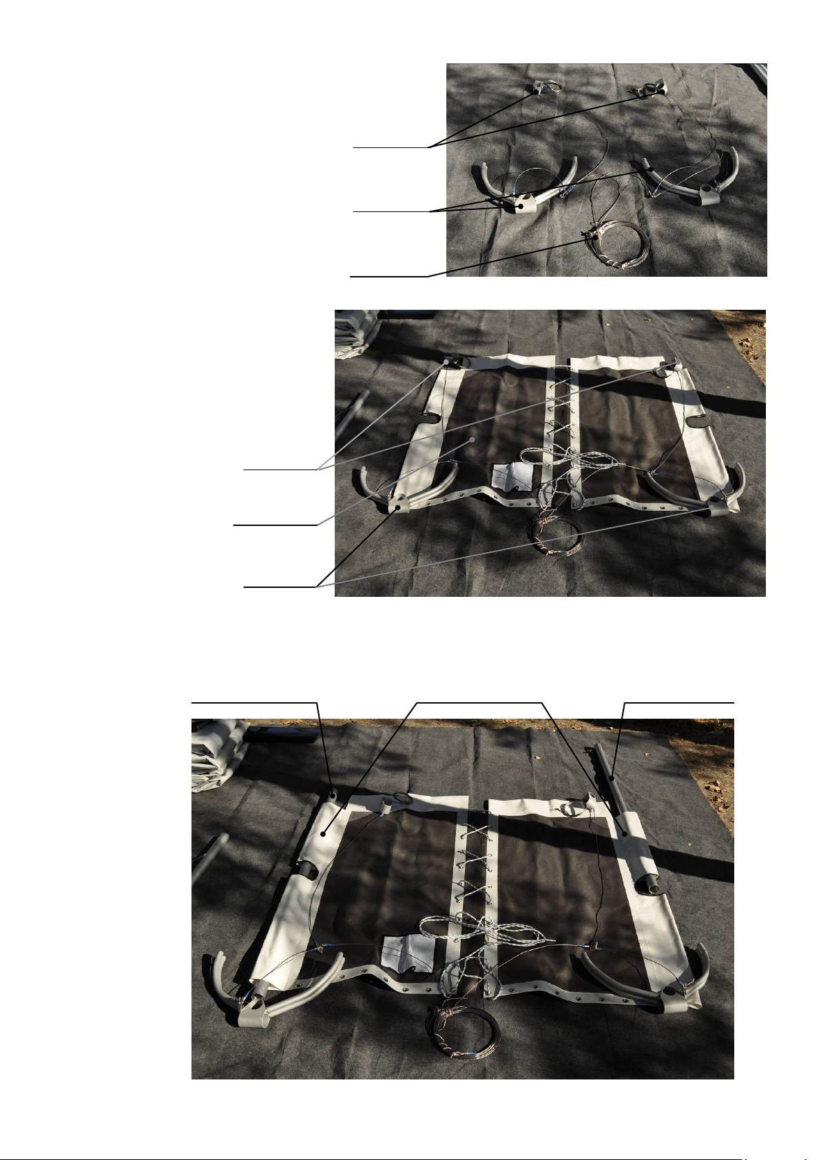
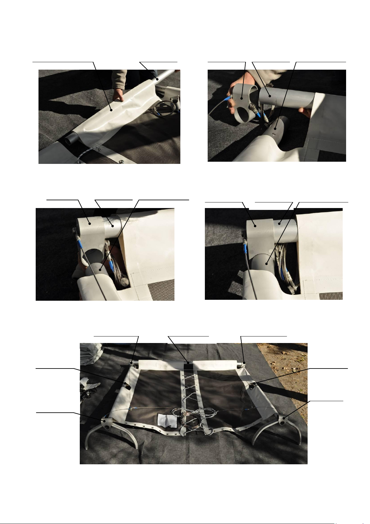
Cargo nets are made from a nylon ribbon and intended for placing of luggage and crew. Cargo
net is put on bow and stringer beams by sleeves and tensioned by lacing to the submast beam.
Bow cargo net’s sleeves are put on the bow and stringer beams and is tensioned by lacing to
submast beam. Stern cargo net’s sleeves are put on the stern and stringer beams and is
tensioned with strapping beam by lacing it at three places.
Centerboard unit consists of the centerboard and the centerboard box. The centerboard is used to
reduce the drift of catamaran when sailing upwind. The centerboard is installed into centerboard
box that attached to submast joint unit. In the operational (vertical) position the centerboard is put
by centerboard trim line and is held by the rubber expander. Expander absorbs the hitting of
underwater obstacles, thus allowing avoid the serious damage of the centerboard. In moorage
(horizontal) position centerboard is raised by halyard and held with clam cleat on the submast joint
unit.
Rudder units consist of two rudder blades, two rudder joint units, two rudder boxes, two tillers
interconnected by tiller crossbar, and two rubber expanders. Rudders are used to control the
catamaran. They are mounted in the rudder boxes, which are attached to the rudder joint units on
stringer stern parts. Rubber expanders put and hold the rudder blades in operational (vertical)
position. Expander absorbs the hitting of underwater obstacles, thus allowing avoid the serious
damage of the rudder blade. In moorage (horizontal) position rudder blades are raised by halyard
and held with clam cleat on every rudder tiller.
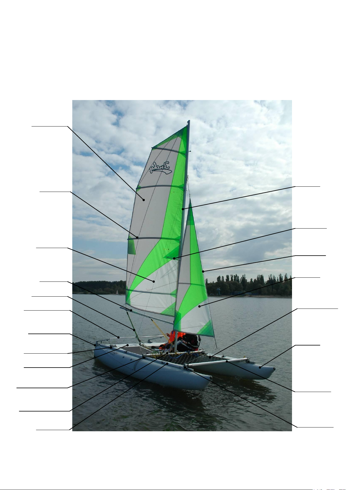
Rigging consists of the mast, sails, boom, standing and running rigging.
The mast consists of four interconnecting segments, spreader and jumper stays.
The mainsail is swayed up by halyard point with a main halyard. The main sail’s tack is fixed with a
downhaul while its clew is attached to the boom by outhaul. Mainsail has battens, which provide
the appropriate shape of sail and the inflexibility of after-leech. Boom is required for control of
mainsail and outhaul serves for sail profile tuning.
Jib is a head sail, which is raised on the mast up by halyard point with the jib halyard. The jib tack is fixed by
the jib downhaul, and the jib sheet is attached to the clew.
Standing rigging includes forestay and shrouds which hold the mast in position. The forestay and
shrouds are attached to mast with a rigging ring (forestay and shrouds are clamped by a rigging ring,
which is put on a mast hook). The shrouds are attached to bridge by guy bridle, and forestay is
attached to bridge by stay bridle. Tensioning of shrouds and forestay is done by forestay's lanyard.
Running rigging are the main-sheet and the jib-sheet.
Main-sheet is intended for a mainsail control. This tackle consists of cord and two blocks, one of
that is attached to boom, and another one with cam cleat - to the sheet beam of catamaran.
Jib-sheet is intended for a Jib control. This tackle consists of cord and two blocks with cam cleats,
which are attached to every end of submast beam.

GENERAL VIEW
Forestay
Stringer
Submast Beam
Submast Gusset
Sheet Gusset
Bow Cargo Net
Tiller Crossbar
Rudder Box
Mainsheet
Sheet Beam
Bow Beam
Float
Jib
Spreader
Mast
Batten
Sail (Main)
Boom
Shroud
Bow Gusset

Bow
Gussets
Submast
Gussets
Sheet
Gussets
Turnbuckle
Packing 1
Packing 2
Packing 3
Packing 4
Duffel Bag
with Sails
CATAMARAN ASSEMBLY
Note: Some parts of your catamaran may differ from those shown
on the photos.
A catamaran is packed into four packing. In packing 1 and 2 there are
pipes of bridge, mast, boom, rudder boxes, centerboard, cargo nets
and trampoline. In the packing 3 there are floats and rudder blades.
In packing 4 there are connecting units (gussets), standing rigging
(shrouds and forestay), centerboard box, sheets and pump. The sails
(main and jib) are packed in separate duffle bag, but, if desired,
could be added into one of the long packing.
1. Take the gussets out from the bag.
Sheet and submast gussets are interconnected by
the cables. Bow gussets are wound up separately
(the turnbuckle is attached to their cables) and are
not connected to any other gussets. At the moment
keep them aside, they will be needed later.
Spreader
Centerboard
Box
Rudder
Boxes
Sail
Stern Net with
Stringer Stern Parts
and Stern Beam
Trampoline
Tiller
Crossbar
Floats
Main-
sheet
Bow Net
and Bow
Beam
Stringer
Bow Parts
Stringer
Middle Parts
Pump
Gussets
Centerboard
Rudders
Boom
Mast

Shroud and
Forestay
Submast
Gussets
Sheet
Gussets
Submast
Gussets
Trampoline
Sheet
Gussets
Stringer Middle
Part
Stringer Middle
Part
Trampoline Side
Sleeves
2. From the rest of four
gussets find out two pairs: submast and
sheet gussets of starboard and submast
and sheet gussets of port. Every pair of
gussets is interconnected by cable (guy
bridle).
3. Roll out the trampoline.
Put gussets on trampoline in the
places where they will be installed in
future.
Make sure that the
cable connecting the
gussets, were not
twisted!
4. Insert the stringer middle parts (two pipes with diameter of 52 mm and length of 1852 mm,
which have the thrust bushings on every end) into trampoline side sleeves.

Trampoline
Transverse Sleeve
Sheet Beam
Sheet
Gusset
Sheet Beam
Stringer Middle
Part
Sheet Beam
Sheet Beam
Stringer Middle
Part
Stringer Middle
Part
Sheet
Gusset
Sheet
Gusset
Sheet Beam
Sheet Gusset
Stringer
Middle Part
Submast
Gusset
Submast
Gusset
Stringer
Middle Part
Sheet Gusset
5. Insert the sheet beam ("bare" pipe with diameter of 52 mm and length of 1950 mm) into
trampoline transverse sleeve. Join the sheet beam and the stringer middle parts with sheet gussets.

Submast
Beam
Centerboard
Box
Submast
Beam
Centerboard
Box
Centerboard
Box
Submast
Beam
Submast
Gusset
Submast Beam
Stringer Middle
Part
Submast Gusset
Submast Beam
Stringer Middle
Part
Stringer Middle
Part
Submast Gusset
6. Assembly the submast beam from two parts and
centerboard box.
7. Join the submast beam and the stringer
middle parts with submast gussets. Make sure that
straight surface end of centerboard box is oriented
towards the bow.

Stringer Bow
Part
т
Stringer Bow Part
Stringer Bow Part
8. Join the stringer bow parts with the stringer
middle parts. For doing so just fully insert the stringer bow
parts into the stringer middle parts. Stringer bow part is a
pipe with diameter of 48 mm having on one end the riveted
peace of pipe with diameter of 45 mm, which has a plastic
cap with screw.
9. Put the sleeves of bow cargo net on stringer bow parts.
Bow Cargo Net

Bow Gusset
Bow Beam
10. Fix the bow beam on stringer bow parts with bow gussets.
11. Connect the bow and stern parts of lower bridle cables. For this put the threaded bush (which is
connected to turnbuckle of bow part of lower bridle) into centerboard box and secure it with screws of stern
part of lower bridle.
Turnbuckle
Threaded Bush
Stern Part of Lower Bridle
with Screw
Centerboard Box

12. Tighten the turnbuckle to remove slack of cables. No need to make a strong tension, the mild
level will be enough! Too hard tension will adversely affect the shape of the floats.
13. Expand and inflate the floats, but not completely, about 90-95%, that in the future will facilitate
the operation of attaching floats to the bridge and lacing of trampoline and cargo net. Set the assembled
bridge on the floats.
14. Install the centerboard into the centerboard box and fix it with screw by tightening it until the
free rotation of centerboard around the screw axis. Screw is threaded into a nut welded to one of the strips
of rigid bridles. Make sure that the edges of the strips adjacent to the centerboard box are parallel, this will
facilitate the process of screwing up. Before installation, it is advisable to set the centerboard trim line in
moor position. Clam cleat to secure the tackle is on submast joint unit.
Turnbuckle
Centerboard Trim Line
Centerboard
Clam Cleat
Centerboard Trim Line
Centerboard

15. Lace up the trampoline and then the bow cargo net to the submast beam. When lacing the
cargo net up, try to make sure that the trampoline lacing and cargo net lacing are not cross each other.
Centerboard
Axle
Rigid
Bridle
Centerboard
Axle
Rigid
Bridle
Bow Cargo Net
Trampoline
Cargo Net Lacing
Trampoline Lacing
Submast Beam

16. Fix the bridge on the floats. Insert the bow parts of every stringer into the proper float pockets,
previously removed the screws from the butts. Secure the cables of float farms with screws.
17. Insert the plugs, which are on cables of float farms, into semi-archs of submast frames.
18. Secure the bridge on the floats with fastening straps, which are on floats.
Fastening strap
Fastening strap
Stringer Bow Part
Stringer Bow Part
Pocket
Bolt
Float Farm Cable
Float Farm Cable
Plug
Submast Frame
Float Farm Cable
Plug
Submast Frame

19. Put stern beam and stringer stern parts into slevees of stern cargo net.
20. Join the stern beam with stringer stern parts.
21. Join stringer stern and middle parts of starboard and port accordingly. To simplify the assembling
process, join the stringers of starboard and port simultaneously.
Stringer
Stern Part
Stern Cargo Net
Stern Beam
Stringer
Stern Part
Stringer Stern Part
Stern Beam
Stern Beam
Stringer Stern Part
Sheet Beam
Sheet Gusset
Stringer
Stern Part
Stern Beam

22. Thread the strapping beam through the stern cargo net.
23. Tension the stern cargo net by banding of strapping beam to sheet beam in three places: at the
ends and in the middle.
24. Fasten the stringer stern parts with remaining straps. Fasten the stringer stern parts with
remaining straps. Inflate the floats till the nominal pressure of 0.15 bar. To prevent the extra load of
compartment partition, do pumping of every float compartments in several steps. When the pressure in the
floats compartments will reach the nominal, further inflating with pump will be difficult.
!!! WARNING:
Do not use air compressor (auto air compressor for tires pumping) as a source of the compressed
air for inflating the floats of your catamaran. Excessive pressure can cause the break of float or
partition.
Strapping Beam
Stern Cargo Net
Sheet Beam
Strapping Beam
Strapping Beam
Sheet Beam
Sheet Beam

25. Assemble the mast. For doing so interconnect the four mast segments.
26. Unravel the jumper stays and place them along the mast. Put two rear side jumper stays on the
eccentrics, which are on the lower mast segment. Fix the central jumper stay. For this, tighten the
turnbuckle, one part of which is on the central jumper stay and another - on the mast.
Mast Segment
Mast Segment
Mast Segments
Mast Segment
Side Jumper
Stay
Side Jumper
Stay
Side Jumper
Stays
Eccentric
Central Jumper
Stay
Eccentric
Turnbuckle
Turnbuckle

27. Mount the spreader on the mast. For doing this, align the spreader spars with the corresponding
holes in the second from bottom mast section.
28. One by one, starting from side rear jumper stays, and finishing with central front jumper stay,
pull a jumper stay like bow-string and put it on spreader spar. Tighten the turnbuckle leaving about 1.5 cm of
thread on each end. So mast should be almost straight if jumper stays are strained properly. Slight bending of
mast at the mast track side is allowed. Secure each jumper stay from sliding out with the locking screw.
Attention!!! There is a high probability of biting the thread and breakage of turnbuckle if you tighten
the turnbuckle under the load when central jumper stay is already on spreader spar. First, adjust the
length of jumper stay with the turnbuckle, and only after that put it on spreader spar. If the length of
jumper stay needs to be corrected, take the jumper stay out from the spreader spar and repeat the
operation again.
Spreader
Spreader
Spars
Locking Screw
Locking Screw
Jumper Stay
Jumper Stay
Jumper Stay
Spreader Spars
Spreader Spar

29. Unravel the forestay and shrouds. Forestay should be in the center, and shrouds - by the sides.
Put the mast at the ball bearing of submast joint unit. Put a ring with shrouds and forestay on a hook, which
is located on the upper section of the mast.
30. Lift and setup the mast into working position by pulling the forestay. Make the tension of
forestay and shrouds by forestay lanyard. Secure lanyard with a bend.
Ball Bearing
Forestay
Shrouds
Forestay
Lanyard

31. Tighten the float farm cables by lanyard. Put the lanyard with several falls, tighten it and secure
with a bend.
32. Setup the rudder boxes onto rudder joint units and fix them with locking rings.
33. Setup the tiller crossbar on the rudder tillers. Fix it with tapper pins and secure it with locking
rings.
Float Farm Cable
Float Farm Cable
Lanyard
Lanyard
Rudder Box
Rudder Joint Unit
Rudder Box
Locking Ring
Tiller Crossbar
Tapper Pin
Rudder Tiller
Locking Ring
Table of contents
Other Ducky Boat manuals