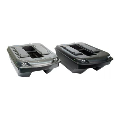
CarpMadness Phantom 2020 Operation instructions

Assemble Instructions
Carp Madness Phantom
Baitboat 2020

We are pleased, that you have chosen the construction set of a CM bait
boat.
The individual parts are selected high quality components, some of them
are specially made for these boats.
The hull is made of ABS, therefore it is very light and dimensionally stable, it can be easily
glued or repaired.
These instructions are intended to facilitate the assembly, but must be implemented by an
experienced modeler. Partly it can be that components are modified due to tolerances or
have to be installed otherwise. These instructions are only intended as a suggestion. There
are several ways to complete the boat.
All parts have been tested for their function before shipment. It is important to pay
attention to the correct connection of the individual components. In addition, the
instructions for use of the components must be read carefully and implemented right to
ensure the correct a use. or damages that are due to a non-professional use, we assume
no warranty.
Please read these instructions and later the operating instructions
carefully and completely before starting to work.
Generally, it makes sense to provide all screws with a screw lock.
But now nothing should get in the way anymore:
Assembly of the hull:
1. Installation of the jet drive and the engine
The opening for the jet engine is already pre-milled.
irst, the herb screen should be glued from the inside into the hall. As with all our bait
boats, we recommend as glue a MS polymer, special adhesive silicone available in almost
every hardware store, e.g. Sikaflex.

Apply enough glue around the opening in the hull to push in the grid. To harden it is best
to place a correspondingly large and heavy piece of wood or something similar on it.
Wet this previously with soapy water, so the silicone adheres only to the grid / hull. It's
best to let it dry for one day. Now fit in the jet. This one should be very easy to insert. If
he fits perfectly, remove it again and, as with the grid, put enough glue around the
opening. Put on the jet and let it stand out through the round opening at the back.
It is best to fix the jet (at the outlet) immediately with superglue and the counter plate
with the 2 small openings (attach externally to the flange) and guide through the two
outer openings a short piece of Bowden cable. So the jet is optimally fixed and can dry. Of
course, a straight seat is important.
After drying, it is important to check the tightness of the complete jet. To do so, immerse
the hull in water and suppress.
There must be no water in the interior of the hull. A leak can be corrected only very
difficult later.

inally, the steering and return unit has to be installed on the outside of the jet. This was
already pre-assembled by us.
irst, the 2 Bowden cables must be glued into the receptacle, greased well and then
screwed onto the steering and return unit.

So the complete jet is put on from behind and firmly screwed. (The bowden cables with
the gray cover are inserted into the 2 openings).
complete jet
.
In the picture you can see the jet with mounted engine, but for gluing you should not
screw the engine yet, only when the jet is really tight, you can screw the engine. But as a
burden for drying the glue you can put them already in the jets.
Caution: always carry out the bonds with enough glue, do not save on the glue, epoxy
resin can be made thicker with a little bit of baking soda for example. However, we
recommend Sika lex or a good adhesive silicone, e.g. Bostik MS.

Before the engine can be screwed on, it must be equipped as follows.
Glue all screws, also the threaded rods with screw locking! The connecting sleeve must
have a small distance (about 1-2 mm) to the motor.
Now you can screw the engine on the jet. It is important that it is sitting straight on the
jet shaft, to this the nuts on the two threaded rods are to tighten crosswise.
It is important that the jet shaft sits completely in the jet, this must be held against from
behind.
Now you can put on the engine and screw.
Use the enclosed piece of wood to create a guide for the 2 Bowden cables. These
correspond to the arrangement drill, attach and also stick together.
It is important to lead it as deep as possible and close to the engine (2-3 mm of air is
sufficient), otherwise the battery holder will later no longer fit. The middle bowden cable
has to sit slightly higher.
inally, the 2 bushings are sticked together and sealed from the inside. Let everything dry
again.
Check tightness again.

Now the controller is to be soldered to the engine. Solder the cables as close as possible to
the engine so that they can go up space-saving on the engine. To do this, extend the
regulator cable. The controller should later sit behind.
Prepare the servo plate with the servo.
Now adjust the servo plate with the servo's to the hull. (the supplied servos may vary in
color)

As a holder for the plate a piece of wood or something similar has to be pasted into. On
this the servo plate is later screwed or only glued.
(An adhesive bond, unlike a bolted joint, is not a rigid connection and can interfere with
the movements to a lesser extent, so we clearly prefer the adhesive bond)
Now it is important to fit the servo exactly. or this purpose, the steering unit of the jet
must be absolutely straight.
Then gently tighten the 2 Bowden cables on the servo arms. The servo's must be as
close to the engine as possible, so that the echo sounder can be installed in the front (or
retrofitted).
Please divide this plate in the middle to get 2 supports for the servo's (feeder flap and
control)

jet completely built-in

Now you should install the radio installation and plug in the receiver as follows (the
brown / black wire must be plugged in away from the receiver):
The remote control is programmed by us with an optimal program for the boat. It may
be useful to make small adjustments to the rashes of the servo's. But this doesn’t have to
be done.
1. Servo for jet steering left and right
2. Regulator / motor
3. Light dimmable
4. Servo for feeder flaps
5. Release coupling
6. nothing
B: if necessary external power supply for receiver
The 2.4 GHz system does not need an antenna on the boat. The receiver must be
taught to the transmitter as needed in accordance with the operating instructions.
It is important that the antenna of the receiver is as high as possible in height,this
menas that the antenna is later also as high as possible over the water level. As well,
no power lines may be located directly next to the receiver.
Plug an accumulator into the controller and turn on the system. (first radio installation,
then boat).
The controller is set automatically (can also be carried out analog in accordance with the
description attached to the controller). These are absolutely high quality components,
which are also responsible for a long life of the boats.
Quite the only thing they do not like is moisture and getting connected to the battery
incorrectly. By the last one mentioned they burn out immediately.
Now the Jet control can be adjusted 100% and the length of the Bowden cables
can be selected. The Servo's should never queue at full scale, but work
smoothly. The engine must run absolutely quietly, without generating any
external noise. The jet must also do its job absolutely quietly.
Lay the cables and wires as shown in the pictures above. The assembly is thus completed.

2. Fitting the feeding flaps
Put the hull upside down on the work table. Rivet or screw the hinges to the two feed
flaps. The holes are predetermined. Then attach the feeding flaps to the two outer
chambers, screw or rivet. After assembly, these have to be tested for perfect running.
If you later look at the finished boat from above, you should not be able to see the hinges.
It is important from the inside to seal the screw connection / riveting by the hull 100%.
After gluing the hull this is no longer possible. Please also test that sufficiently.
view from the inside

Triggering the two flaps:
The inner part of the Bowden cable must exercise the support function under the flaps.
Drill the hull at the correct height, the plastic part and the sheath of the Bowden cable are
to stuck in there continuously.
Position is as far forward as possible, but no further than that you can hang the battery
compartment later. It should be about 1 mm of air between the closed flap and the
Bowden cable. More is not necessary, as the cord is guided in the recess of the fuselage.
Cut the Bowden cable to the correct length after curing.
The servo is also screwed into a servo plate. The servo plate should be cut off in the
middle. Mount the inner part of the Bowden cable on the servo arm and then push the
whole thing completely into the prepared seat.
Before that it’s absolutely necessary to grease the Bowden cable. This is important for the
tightness of this control, as it is by a fully charged boat under the water surface.
In addition, we recommend using the adhesive silicone to spray a seal on the Bowden
cable so that it rests halfway on the shell half on the Bowden cable (on each side).
The fact that the Bowden cable is greased, the cured silicone adheres only to the shell and
not the Bowden cable. After complete curing it results in an optimal and durable seal.
Screw or stick on the servo plate.
The hull is ready. All functions have to be tested again. The lower shell can now be
carefully driven on the water.
The boat should be slightly tilted backwards in the unloaded state
on the ater. Good to test in the bathtub. Just balance out there. This is very important
to steer the boat later optimal. Take your time.

1. Glue the Bowden cable bushing with plastic support elements
2. Cut off the cover in the correct length
3. Preparing oft he mechanism

4. Install the servo on mounting plate
5. inally seal with sealant 100%
3. Optional echo sounder and GPS:
The echo sounder is in the front, the GPS behind at the top of the rectangle of the hull.
At the front and at the back are also the antennas to mount.
We recommend to use the main accumulators as a power source and to attach one or two
switches, depending on your personal preference.
or this purpose, a branch is to be laid in the lid so that it can be soldered to the power
supply of the echo sounder and the GPS after bonding the lid.
Also mount these live cables on the outside of the lid circumferential (see mounting cover)

Mounting of the lid:
1. At first the attached LEDs are mounted.
The diodes supplied by us are pre-assembled and ready. These diodes are designed for
12 volts and only need to be screwed into the already milled holes of the hull.
During assembly, these should still be completely seale
d. Be sure to secure the sockets after the screwing, as this area of the boat will be difficult
to reach after gluing.
We recommend to connect the diodes parallel, because then the other diodes still work, if
one fails. That means bringing all + poles together and soldering all -poles together. In
this circuit, the "dimmable light relay" has to be installed as in the parts description /
sticker.
We recommend soldering the diodes directly to the boat batteries.
To do this, install a power take-off at the supply lines of the controller.
Lay the live cables around the outside, not in the center shaft.
As well the power supply for the GPS / echo sounder. This is important because the later
receiver sits in the middle shaft and does so not sit in the slipstream of the live cables.
Of course check the function completely before gluing.
inished.

Installation of the main switch:
We recommend our illuminated switch, which replaces the small switch on the controller
after gluing the hull.
This small switch on the controller should be cut off and replaced with the main switch as
follows:

Assembly of the release coupling:
The position of the release coupling can be freely selected. We recommend at the back of
the first slope of the lid, as it is so then protected against rain. Only then you can define
the position of the servo on the subshell. Carry out white sticks and glue the servo at the
line of inside of the lid.

Assembly oft he voltage indicator:
The attached voltage indicator must be soldered between the poles of the accumulators
(in front of the controls). You can test these by for example taking a 9 V battery and
connect it.
or this, the digital display must show the voltage. Attention: the lipo's must not be driven
under 6.4 - max. 6 V, because they are destroyed then. The display can also be made
switchable if a supply line is routed via the main switch.
.

Assembly of the lid
The threaded bushes are screwed into the upper shell and secured with adhesive silicone.
The handle has to be mounted in the middle of the lid.

Sticking of the hull:
After everything works perfectly, the two pieces can be glued. Please note that the two
pieces can not be separated anymore.
It is important to pay attention to clean and grease-free adhesive surfaces. or safety,
clean the surfaces on the outside and on the inside with some solvent.
Apply the appropriate adhesive (we recommend a special adhesive silicone, as the
residues can be easily removed later) at least 5 mm even and circumferential thick. The
outer glue line is later no longer accessible.
Now press the lid onto the hull
.
In addition we recommend to rivet. It's best if the material spills out everywhere. Then the
hull is 100% tight.
Now it is essential to allow the boat to cure completely, because movements
(even in the water !!) can cause the joints to open and are only very difficult to
seal afterwards.
inally, connect the cables to the main switch, GPS or echo sounder. The battery box only
has to be hung in the opening.
CONGRATULATIONS, now everything is ready.
Pay special attention to the individual instructions of the components, such as
Lipo batteries, charger etc. and to the instructions of the boat.
You can always contact us if you have problems with the assembly.
Other CarpMadness Boat manuals