Duemmegi Domino DFANA-M/CC User manual
Domino
DFANA-M/CC
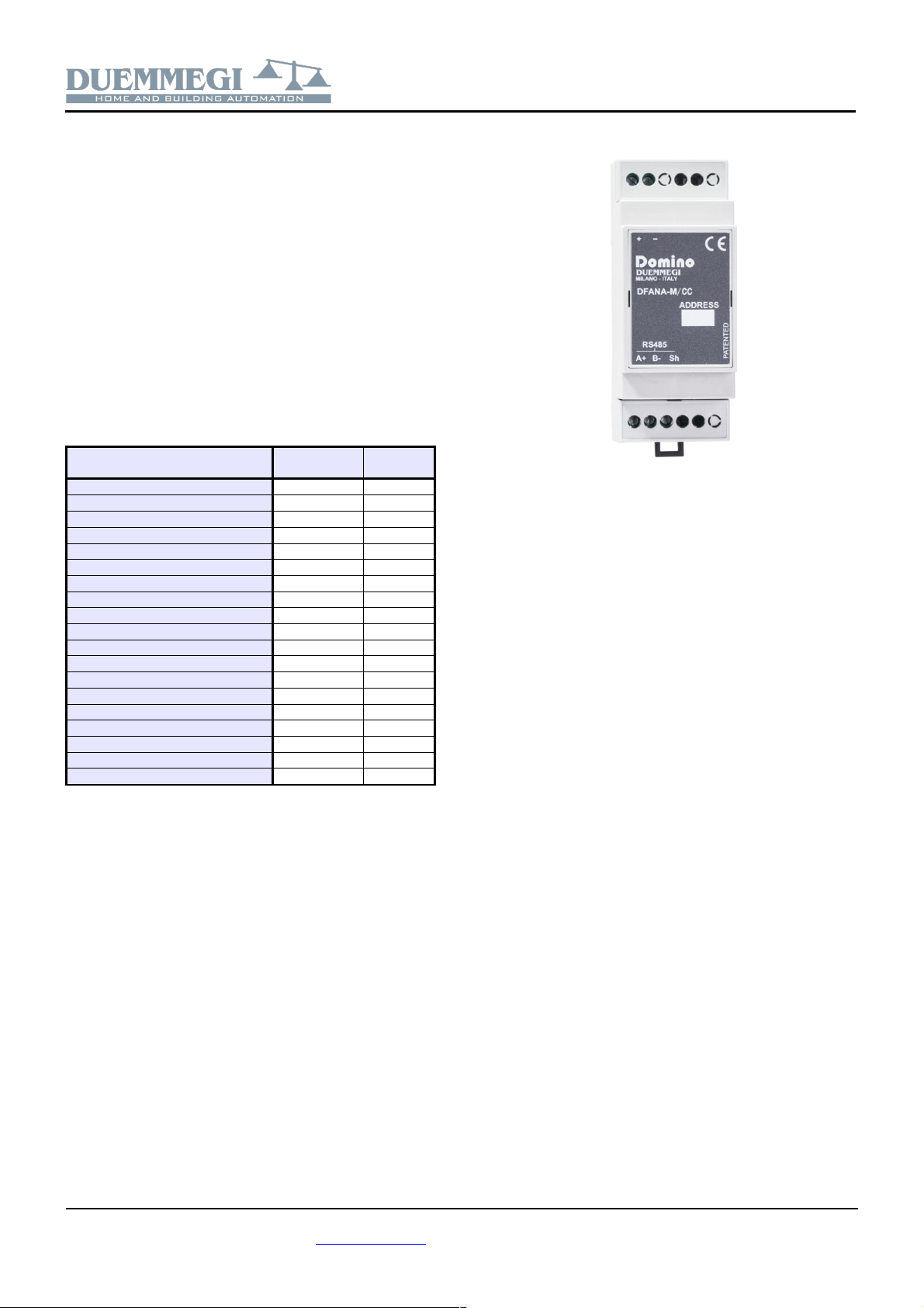
DFANA-M/CC: Load-shedding controller
for Domino bus
DFANA-M/CC and DFANA-S modules allow the measure-
ments of several electrical parameters including the man-
agement of load-shedding, both for single-phase and
three-phase networ . DFANA-M module interfaces directly
to the Domino bus, thus ma ing the measurements imme-
diately available and easy to use. The measurements are
also shown on the front panel of DFANA-S by a bac -light-
ed LCD display.
DFANA-M/CC module integrates an algorithm which, in
combination with relay output modules (e.g. DF4RI,
DF8RIT), creates a complete sequential load-shedding sys-
tem.
DFANA-M/CC reports on the Domino bus the 19 measure-
ments listed in the following table:
Measurement Symbol Measured
units
Voltage phase 1 (*) V1N [V]
Current phase 1 (**) I1 [A]
Active power phase 1 P1 [W]
Apparent power phase 1 S1 [VA]
Reactive power phase 1 Q1 [VAR]
Power factor phase 1 PF1 -
Voltage phase 2 (*) V2N [V]
Current phase 2 (**) I2 [A]
Active power phase 2 P2 [W]
Apparent power phase 2 S2 [VA]
Reactive power phase 2 Q2 [VAR]
Power factor phase 2 PF2 -
Voltage phase 3 (*) V3N [V]
Current phase 3 (**) I3 [A]
Active power phase 3 P3 [W]
Apparent power phase 3 S3 [VA]
Reactive power phase 3 Q3 [VAR]
Power factor phase 3 PF3 -
Total positive active energy (***) Wh(+) [Wh]
(*): Voltages are sent on the bus multiplied x 10
(**): Currents are sent on the bus multiplied x 100
(***): Energy can be reset via bus
DFNA-M/CC module features a 2-way fixed terminal bloc
for the connection to Domino bus and a 3-way fixed termi-
nal bloc s for the connection to DFANA-S module.
For information about terminal bloc s, connections and the
several possible settings of the measurements section of
DFANA-S module, refer to the related User's Manual
(DFANA-S_xxMIT).
Near to the bus terminal bloc , DFANA-M/CC module fea-
tures a small pushbutton and a green LED that shows the
operating status; this LED normally flashes every 2 sec-
onds about to signal that the module is properly connected
to the bus. DFANA-M/CC module is housed in a standard
2M modular box for rail mounting
Load-shedding operation
DFANA-M/CC module, as mentioned, allows to manage
the power consumption a three-phase (or single-phase)
electrical system, avoiding the intervention of the meter
protection due to the simultaneous switching on of loads
with excessive total power. DFANA-M/CC can manage up
to 24 different loads in three-phase mode and 8 loads in
single-phase mode. The module ta es into account the dir-
ection of the current, therefore it can be used in systems
equipped with a photovoltaic generator. DFANA-M/CC
module can wor both in systems with DFCP controller and
in the absence of this one.
The module continuously measures the total active power
absorbed by the connected loads and this value is com-
pared to the threshold value fixed during the setting up
through the support program BDTools or DCP Ide. If the
value exceeds the threshold, it begins to disconnect the
loads in sequence until the total power returns below the
threshold. The loads to be disconnected from the system if
the threshold is exceeded are connected to output modules
with power relays (e.g. DF4RI or DF8RIT) which, through
the Domino bus, are lin ed to the DFNA-M/CC module us-
ing equations programmed in the output modules.
If an overload occurs, the first load that is disconnected will
be number 24 (which must be with the one less important
for the user). Disconnection occurs 5 seconds after the
threshold is exceeded; in this case, if the overload condi-
tion still persists, the module will disconnect the sub-
sequent loads until the total power returns below the
threshold.
The reconnection of the last disconnected load ta es place
in any case after a maximum time from its disconnection
(parameter TOff Max), or after a shorter time if the condi-
tions established by a precise algorithm exist.
However, it is possible to prevent a load from being discon-
nected, or it is possible to reconnect it after a disconnec-
tion, by acting on the relative point of the module output ad-
dress (see following paragraphs).
DUEMMEGI s.r.l. - Via Longhena, 4 - 20139 MILANO
Tel. 02/57300377 - Fax 02/55213686 – www.duemmegi.it
Rel.: 1.0 June 2021 Page 1 of 6

Domino
DFANA-M/CC
Address programming
DFANA-M/CC module ta es the following addresses on the
Domino bus:
✗three-phase mode: 30 input addresses and 3 optional
output addresses 3 with a value equal to base ad-
dress, base address + 10 and base address + 20
✗single-phase mode: 10 input addresses and 1 optional
output address with a value equal to base address
The base address can be assigned by DFPRO program-
mer or by BDTools or DCP IDE. A white label on the front
panel allows the writing of the assigned base address for
an immediate visual identification.
Module connection
The following schematic diagram shows the connection be-
tween DFANA-M/CC, DFANA-S and and Domino bus.
A
B-
9 7 6 4 3 1 | 65 64
2 5 8 11 20 21
ENTER
L1 L2 L3 N SUPPLY
POWERVOLTAGE INPUT
L1L2L3
CURRENT INPUT
A+ B-
RS485
DUEMMEGI FANA-S
BUS _
RS485
A+ B- Sh
DUEMMEGI
MILANO-ITALY
ADDRESS
DFANA-M/CC
_
Domino
PATENTED
For details about the connection to the AC line and to the
aux power supply, refer to the related User's Manual
(DFANA-S_xxMIT.
Information reported on the bus
Input section
As already mentioned, the DFANA-M / CC module ta es,
inside the Domino bus, up to 30 input addresses reporting
the ON/OFF status of the individual loads and the mea-
surements of the various electrical parameters for each
phase; in single-phase configuration, only the first bloc of
10 addresses has to be considered. The following tables
show how the information in the 3 bloc s is mapped.
Phase 1 or single phase:
IN
Addr 16..12 11 10 9 8 7 6 5 4 3 2 1
n-S
1- - C
24
C
23
C
22
C
21
C
20
C
19
C
18
C
17
n 1 Voltage phase 1
n 2 Current phase 1
n 3 Active power phase 1
n 4 Apparent power phase 1
n 5 Reactive power phase 1
n 6 Power factor phase 1
n 7 Positive active energy Wh
n 8 Positive active energy Wh, byte LSB
n 9 Positive active energy Wh, byte MSB
Phase 2:
IN
Addr 16..12 11 10 9 8 7 6 5 4 3 2 1
n 10 -S
2- - C
16
C
15
C
14
C
13
C
12
C
11
C
10
C
9
n 11 Voltage phase 2
n 12 Current phase 2
n 13 Active power phase 2
n 14 Apparent power phase 2
n 15 Reactive power phase 2
n 16 Power factor phase 2
n 17 Positive active energy Wh
n 18 Positive active energy Wh, byte LSB
n 19 Positive active energy Wh, byte MSB
Phase 3:
IN
Addr 16..12 11 10 9 8 7 6 5 4 3 2 1
n 20 -S
3- - C
8
C
7
C
6
C
5
C
4
C
3
C
2
C
1
n 21 Voltage phase 3
n 22 Current phase 3
n 23 Active power phase 3
n 24 Apparent power phase 3
n 25 Reactive power phase 3
n 26 Power factor phase 3
n 27 Positive active energy Wh
n 28 Positive active energy Wh, byte LSB
n 29 Positive active energy Wh, byte MSB
The first input address of each one of the three bloc s (n, n
+ 10 and n + 20) report 16 digital points which, instead of
being connected to “physical contacts”, are managed by
the module itself. The first 8 points of each bloc (Cx) cor-
respond to a load; when the state of a point is 1 (ON) the
load must be connected. These “virtual” input points will
then be used as described below.
Point 11 of each bloc (S1, S2 and S3), when active, indi-
cates that at least one load of that bloc has been discon-
nected.
If the power threshold is exceeded, the disconnection se-
quence starts from the higher order load towards the lower
order one (from C24 to C17 in single-phase, from C24 to
C1 in three-phase).
DUEMMEGI s.r.l. - Via Longhena, 4 - 20139 MILANO
Tel. 02/57300377 - Fax 02/55213686 – www.duemmegi.it
Rel.: 1.0 June 2021 Page 2 of 6

Domino
DFANA-M/CC
The points in the input section at base address must be
used in the programming of Domino system to control the
loads (up to 8 in single-phase mode and up to 24 in tree-
phase mode), adding to relay output modules a simple
equation as in the following example:
O31.1 = I41.1
where O31.1 is the relay output controlling the load 1 and
I41.1 is the point 1 of DFANA-M/CC having base address
41. Of course, up to 24 equations of this type are needed,
one for each load to be controlled.
Regarding the electrical parameter measurements, the fol-
lowing considerations apply:
✗voltages are expressed in V multiplied by 10 (e.g. a
230.4V voltage will be sent on the bus as 2304)
✗currents are expressed in A multiplied by 100 (e.g. a
current 22.65A will be sent on the bus as 2265)
✗active powers (symbol P) are expressed in W and
they are given in two's complement (since they can as-
sume negative value) in the range -32768 to +32767;
e.g. if the active power is 1825W, the module will send
on the bus the value 1825. A negative value of the ac-
tive power means that the system is yielding energy
rather than consuming it (e.g. photovoltaic system).
✗apparent powers (symbol S) are expressed in VA and
they have always positive values; e.g. if the apparent
power is 2478VA, the module will send on the bus the
value 2478.
✗reactive powers (symbol Q) are expressed in VAR
and they are given in two's complement (since they
can assume negative value) in the range -32768 to
+32767; e.g. if the reactive power is 357VAR, the mod-
ule will send on the bus the value 357.
✗power factors (symbol PF) are multiplied by 1000 and
they are given in two's complement in the range -1000
to +1000; e.g. if the PF is 0,985, the module will send
on the bus the value 985. The PF is dimensionless.
The power factor is the ratio P/S (active power divided
by apparent power) and it gives an indication of the
phase shift of the voltage with respect to the current;
the sign of PF has the following meaning:
○PF positive → inductive load
○PF negative → capacitive load
✗the last 3 addresses of each bloc report the same val-
ue and they allows to calculate the total active energy
( Wh); the formula to have the value in Wh is:
65536 x V(n+9) + V(n+8) + [V(n+7) / 1000]
where V(n+9), V(n+8) and V(n+7) are the values at
the input addresses [n+9, n+8 e n+7] respectively. The
same result can be obtained by using the triplet of val-
ues at addresses [n+19, n+18 e n+17] and [n+29,
n+28 e n+27].
Output section
In addition to the input addresses already described, the
DFANA-M/CC module ta es the following optional output
addresses:
✗three-phase mode: 3 output addresses with a value
equal to base address, base address + 10 and base
address + 20
✗single-phase mode: 1 output address with a value
equal to base address
9 digital points are available on each output address n. The
first 8 allow to avoid the disconnection of the related load:
when the state of a point is 1 (ON) the load always remains
connected. Point 9, when activated, resets the Energy
counter ( Wh). The following tables show how the informa-
tion on the 3 output addresses is mapped .
Fase 1 o monofase:
OUT
Addr 16..11 10 9 8 7 6 5 4 3 2 1
n- -
Reset Energy counter
C24 always connected
C23 always connected
C22 always connected
C21 always connected
C20 always connected
C19 always connected
C18 always connected
C17 always connected
Fase 2:
OUT
Addr 16..11 10 9 8 7 6 5 4 3 2 1
n 10 - -
Reset Energy counter
C16 always connected
C15 always connected
C14 always connected
C13 always connected
C12 always connected
C11 always connected
C10 always connected
C9 always connected
Fase 3:
OUT
Addr 16..11 10 9 8 7 6 5 4 3 2 1
n 20 - -
Reset Energy counter
C8 always connected
C7 always connected
C6 always connected
C5 always connected
C4 always connected
C3 always connected
C2 always connected
C1 always connected
Note: the output section of the DFANA M/CC module can
not be programmed using equations. The listed output
points must be controlled by the supervisor by writing the
desired point, or by I/V table (see in the next pages).
DUEMMEGI s.r.l. - Via Longhena, 4 - 20139 MILANO
Tel. 02/57300377 - Fax 02/55213686 – www.duemmegi.it
Rel.: 1.0 June 2021 Page 3 of 6
Domino
DFANA-M/CC
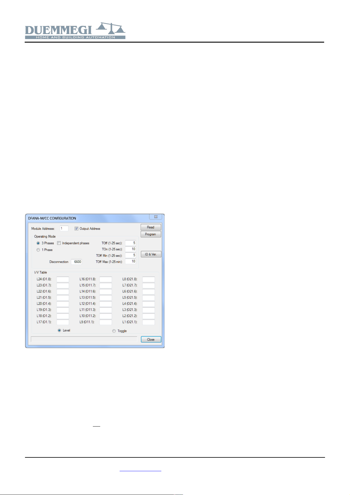
DFANA-M/CC configuration panel
The configuration panel in BDTools and DCP IDE allows to
configure DFANA-M/CC module as required.
The configuration of the module is performed through the
Domino bus as described below.
If DFCP controller is used, all DFANA-M/CC modules in-
stalled in the system must be declared in the configuration,
specifying their addresses as in the following example,
where it is assumed to have a single DFANA-M/CC config-
ured for three-phase mode with base address 22 and en-
abled output addresses:
DFANA-M/CC = ( I22, I23, I24, I25, I26,
I27, I28, I2 , I30, I31, O22 )
DFANA-M/CC = ( I32, I33, I34, I35, I36,
I37, I38, I3 , I40, I41, O32 )
DFANA-M/CC = ( I42, I43, I44, I45, I46,
I47, I48, I4 , I50, I51, O42 )
From the main menu of DCP IDE select Configuration, En-
ergy Management, and then DFANA-M/CC; the following
window will be shown:
The meaning of the several fields is described below.
Module Address: it is the base address of DFANA-M/CC
module to be configures or to be read
Output Address: enabling these parameter, the output ad-
dress (or addresses for 3-phases mode) will be activated
3-Phases / 1-Phase: operating mode selection
Independent phases: this option affects three-phase
mode only; if this option is not activated, the module will
ta e into account the total three-phase power and will per-
form the load shedding starting from load 24 to arrive to 1.
If instead this option is activated, the 3 powers of each
phase will be considered and the load disconnection will
ta e place from C24 to C17, from C16 to C9 and from C8
to C1 independently; this operating mode is equivalent to 3
DFANA-M/CC modules configured in single-phase mode
TOff (1-25 sec): it is the time that elapses between the dis-
connection of one load and the next if the power has not re-
turned below the threshold
TOn (1-25 sec): it is the time that elapses between the re-
connection of one load and the next if there is power avail-
able to do so
TOff Min (1-25 sec): it is the minimum time during which a
load remains disconnected; in other words, if the conditions
exist to reconnect the load just disconnected but this has
been disconnected for less than "TOff Min" seconds, then
one still waits for "TOff Min" seconds before reconnecting it
TOff Max (1-25 min): is the maximum time during which a
load can remain disconnected; in other words, if within “Toff
Max” minutes the measured power does not return below
the value established by the re-connection algorithm, the
load will be reconnected anyway
Disconnection (Watt): it defines the threshold for discon-
nection (Watt): the active power value (in Watt) beyond
which the load disconnection sequence begins; the discon-
nection of the first load ta es place with a maximum delay
of 5 seconds from exceeding the threshold. This value,
generally, should be set equal to the size of your counter
incremented by 10%; for example, for a 3 W meter, this
threshold could be 3300W
I/V Table: it is useful to change the states of “Cx always
connected” output points (see output sections) by acting on
switches, buttons or other connected to Domino bus input
modules. In other words, in this section you can specify the
input points (real or virtual) which, when activated, must en-
able or disable the disconnection of the corresponding load
Level / Toggle: it defines the behavior of the points de-
clared in the I/V Table . In Level mode, the output point that
disables the disconnection of the related load follows the
status of the I/V input point (therefore if the point is active
the disconnection is disabled, vice-versa if the point is dis-
abled the disconnection is enabled). In Toggle mode, the
output point that disables the disconnection of the relative
load changes state at each OFF-ON variation of the I/V in-
put point (therefore at each OFF-ON variation the discon-
nection is enabled/disabled.
Read: transfer the current configuration of DFANA-M/CC to
the configuration window
Program: transfer the configuration currently displayed in
the window to DFANA-M/CC
ID & Ver.: as to DFANA-M/CC the ID code and the
firmware version.
DUEMMEGI s.r.l. - Via Longhena, 4 - 20139 MILANO
Tel. 02/57300377 - Fax 02/55213686 – www.duemmegi.it
Rel.: 1.0 June 2021 Page 4 of 6

Domino
DFANA-M/CC
Mapping
The map of DFANA-M/CC module can be displayed by BD-
Tools or DCP IDE as shown in the following figure; this fig-
ure relates to only one of the 3 sections of the module.
The points identified IN1 .. IN8 are related to the base input
address; the status of these points is shown by a green
“dot” if the point is not active or red if the point is active.
The points identified OUT1..OUT8 and RESET Wh are re-
lated to the output address (if enabled); the status of these
points is represented by a green “square” if the point is not
active or by a red “square” if the point is active.
The central section of the symbol shows the measured val-
ues as indicated.
As usual, the bac ground of the module is shown in green
when it is connected and wor ing, otherwise the bac -
ground will be red.
Outline dimensions
90mm
35,8mm 58mm
RS485
A+ B- Sh
DUEMMEGI
MILANO-ITALY
ADDRESS
DFANA-M/CC
_
Domino
PATENTED
Technical characteristics
Power supply, bus side By specific centralized power
supply mod. DFPW2
MAX current consumption bus
side
Equivalent to 2 standard mod-
ules
Communication protocol and
parameters for DFANA-S
MODBUS RTU, slave addr.=1,
9600 baud, no parity, 8 data
bits, 2 stop bits
RS485 cable type for connec-
tion to DFANA-S
Twisted pair, shield is not need-
ed (if available, connect it to ter-
minal Sh)
RS485 cable max length 5 meters
Amount of managed loads Up to 8 in 1-phase mode and
up to 24 in 3-phase mode
Threshold for load shedding Up to 16.777.215 MAX
Available measurements for
each phase
Voltage RMS
Current RMS
Active power
Apparent power
Reactive power
Power factor
Total active energy
Operating temperature range -5 ¸ +50 °C
Recommended operating tem-
perature range
+5 ¸ +40 °C
Storage temperature -20 ¸ +70 °C
Protection degree IP20
Note: For more information about the technical characteristics of
the measurements section DFANA S, refer to the user's manual
DFANA S_xxMIT.
DUEMMEGI s.r.l. - Via Longhena, 4 - 20139 MILANO
Tel. 02/57300377 - Fax 02/55213686 – www.duemmegi.it
Rel.: 1.0 June 2021 Page 5 of 6

Domino
DFANA-M/CC
Correct disposal of this product
(Waste Electrical & Electronic Equipment)
(Applicable in the European Union and other
European countries with separate collection sys-
tems). This mar ing on the product, accessories or
literature indicates that the product should not be
disposed of with other household waste at the end
of their wor ing life. To prevent possible harm to
the environment or human health from uncontrolled waste dispos-
al, please separate these items from other types of waste and re-
cycle them responsibly to promote the sustainable reuse of materi-
al resources. Household users should contact either the retailer
where they purchased this product, or their local government of-
fice, for details of where and how they can ta e these items for en-
vironmentally safe recycling. This product and its electronic ac-
cessories should not be mixed with other commercial wastes for
disposal.
Installation and use restrictions
Standards and regulations
The design and the setting up of electrical systems must be per-
formed according to the relevant standards, guidelines, specifica-
tions and regulations of the relevant country. The installation, con-
figuration and programming of the devices must be carried out by
trained personnel.
The installation and the wiring of the bus line and the related de-
vices must be performed according to the recommendations of the
manufacturers (reported on the specific data sheet of the product)
and according to the applicable standards.
All the relevant safety regulations, e.g. accident prevention regula-
tions, law on technical wor equipment, must also be observed.
Safety instructions
Protect the unit against moisture, dirt and any ind of damage dur-
ing transport, storage and operation. Do not operate the unit out-
side the specified technical data.
Never open the housing. If not otherwise specified, install in closed
housing (e.g. distribution cabinet). Earth the unit at the terminals
provided, if existing, for this purpose. Do not obstruct cooling of the
units. Keep out of the reach of children.
Setting up
The physical address assignment and the setting of parameters (if
any) must be performed by the specific softwares provided togeth-
er the device or by the specific programmer. For the first installa-
tion of the device proceed according to the following guidelines:
Chec that any voltage supplying the plant has been removed
Assign the address to module (if any)
Install and wire the device according to the schematic dia-
grams on the specific data sheet of the product
Only then switch on the 230Vac supplying the bus power sup-
ply and the other related circuits
Applied standards
This device complies with essential requirements of the following
directives and norms:
2014/30/UE (EMC)
2014/35/UE (Low Voltage)
2011/65/UE (RoHS)
Note
Technical characteristics and this data sheet are subject to change
without notice.
DUEMMEGI s.r.l. - Via Longhena, 4 - 20139 MILANO
Tel. 02/57300377 - Fax 02/55213686 – www.duemmegi.it
Rel.: 1.0 June 2021 Page 6 of 6
This manual suits for next models
1
Table of contents
Popular Measuring Instrument manuals by other brands

Powerfix Profi
Powerfix Profi 278296 Operation and safety notes

Test Equipment Depot
Test Equipment Depot GVT-427B user manual

Fieldpiece
Fieldpiece ACH Operator's manual

FLYSURFER
FLYSURFER VIRON3 user manual

GMW
GMW TG uni 1 operating manual

Downeaster
Downeaster Wind & Weather Medallion Series instruction manual

Hanna Instruments
Hanna Instruments HI96725C instruction manual

Nokeval
Nokeval KMR260 quick guide

HOKUYO AUTOMATIC
HOKUYO AUTOMATIC UBG-05LN instruction manual

Fluke
Fluke 96000 Series Operator's manual

Test Products International
Test Products International SP565 user manual

General Sleep
General Sleep Zmachine Insight+ DT-200 Service manual


