Page 9 of 12
OPERATION
Cougar fan coils provide cooling and heating of air
when used in conjunction with chilled water and/or low
temperature hot water systems. They are designed for
mounting in a ceiling or roof void, connected to
ductwork.
When running, the fan draws air from the room and the
primary air supply, through an inlet filter and over the
finned tubes of a heating/cooling coil. The air is then
discharged through spigots, along ductwork and
through grilles or diffusers to the room space.
Alternative options include chilled water cooling only,
and intake through ductwork and spigots.
Fans normally run continuously, with an automatic
control system varying the flow rates of chilled water
and hot water through the coil (waterside control), thus
varying the cooling and heating outputs. Depending
upon the particular type of controls fitted, user control
is provided by 0-10VDC signal and/or temperature
control.
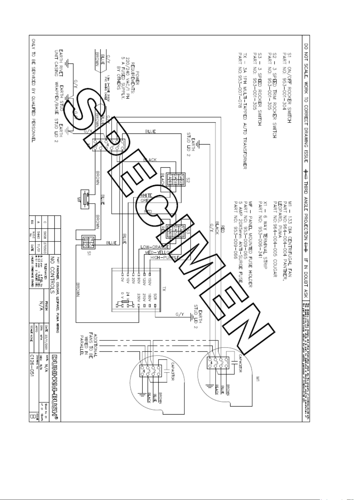
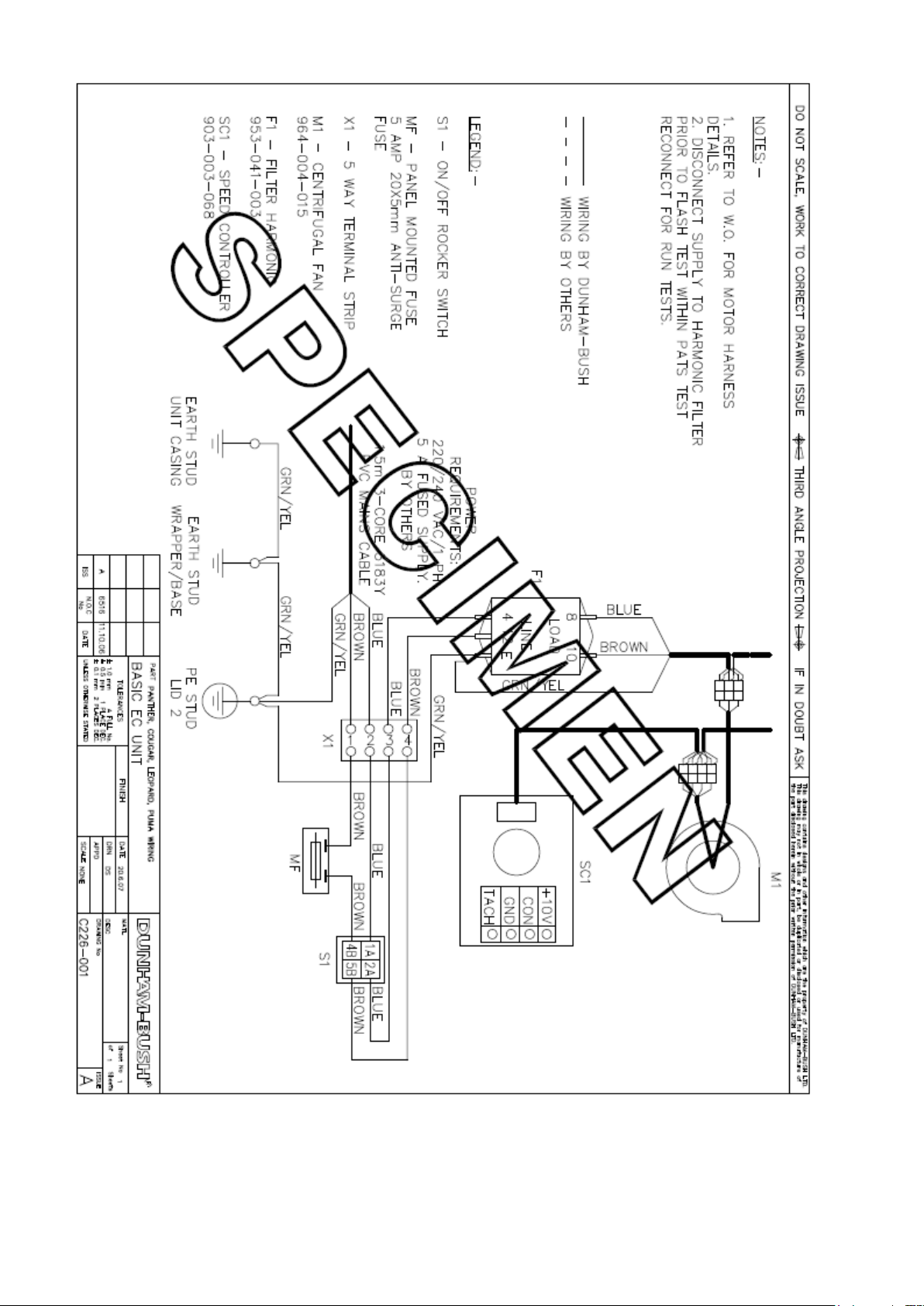
CONTROLS
Cougar fan coil units are fitted with a waterside control
system, which typically comprises the following
elements: -
Fitted fan on/off switch
Fan speed change switches (AC motor units)
Fan speed potentiometer (EC motor units)
Fan coil controller
Return air sensor
Valve actuators (Two or four port valves)
Additional optional accessories include: -
Remote room air sensor
Remote setpoint adjuster
Remote fan on/off and speed switches
Fitted relays for master/slave or BMS control
Dunham-Bush also fit non-standard controls supplied
by others; refer to the wiring diagram supplied with the
unit.
CLEANING
Cleaning and maintenance must be carried out by
competent persons
Inspection
The frequency of cleaning and inspection depends
upon the conditions in which the fan coil unit
operates. Initially, it is suggested that the air filter
and drip tray are inspected after 6-8 weeks normal
operation.
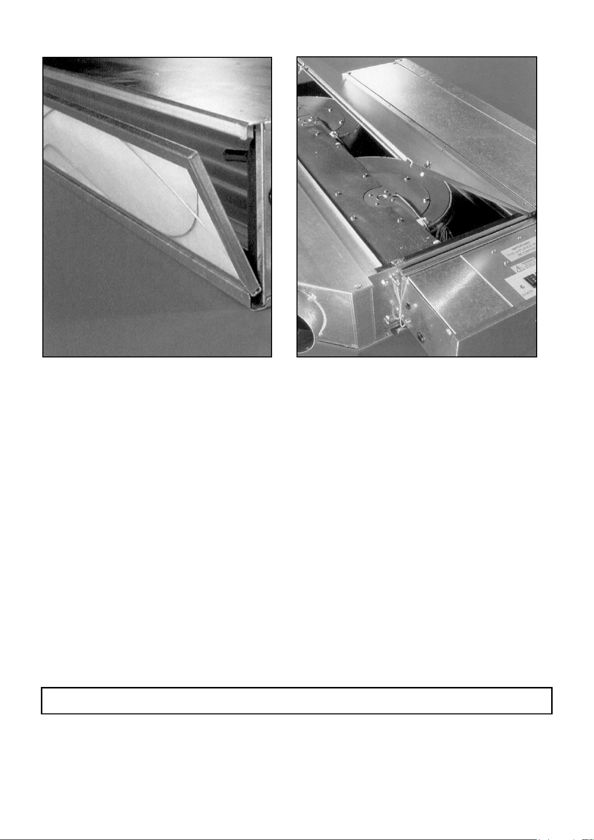
Access
There are four access panels - filter, drip tray/coil,
fans/motors and discharge plenum. All access
panels can be opened by removing screws and
turning quarter-turn fasteners.
The filter can be removed by sliding it out from its
mounting on the fan coil inlet, or from below by
removing its access panel
.
Cleaning
1. Air filters can be cleaned by tapping out
excess dust and washing in warm water (up
to 40°C), using detergent if necessary. The
filter must be rinsed and allowed to dry
naturally before replacing. Do not use a
vacuum cleaner, as it can damage the filter
media. Filters should be replaced after
approximately 20 washes.
2. The drip tray can be cleaned with warm,
soapy water. Ensure the drip tray drains
freely.
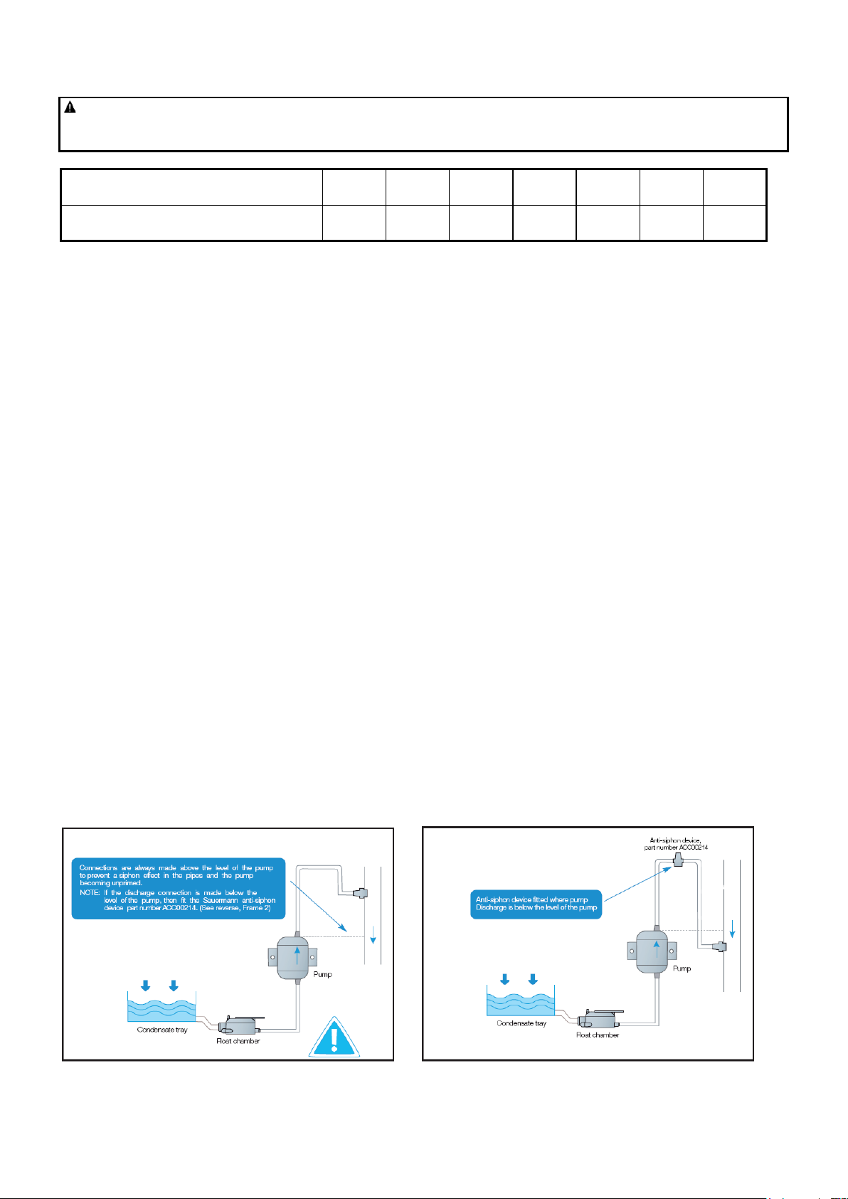
3. If a condensate pump is fitted, check any
sensors are clean and wiped dry. Test the
operation of the pump by pouring clean water
into the drip tray.
Because the air filter retains most of the dusty
particles, it will only be necessary to clean the fans,
motors and coil annually. An industrial vacuum
cleaner can be used to clean the inside of the fan
coil, in particular the coil and fans, with the air being
sucked through the coil in the opposite direction to
normal air flow. All accessible surfaces can be
cleaned with a cloth.