Dura-Max 26063 User manual

16’’ (40.6cm) REEL MOWER
TM
Item: 289516
Model: 26063
Owner's Manual
TOLL FREE HELPLINE:1 866 456-8934
IMPORTANT:
Read and follow all safety rules and operating instructions before using this product.

TABLE OF CONTENTS
………………………………………………………………………………….…………..…………………3
………………………………………………………………………….…………..…………………2
2
PRODUCT SPECIFICATIONS
SAFETY INFORMATION
………………………………………………………………………….…………..……………….4/6
ASSEMBLY INSTRUCTIONS
CUTTING HEIGHT ADJUSTMENT
BLADE ADJUSTMENT ………………………………………………………………….…………..…………....…..
………………………………………………………………….…………..…………....…....................7
7
CARE AND MAINTENANCE…………………………………………………………………………….…………..………………….3
CHECKING THE ADJUSTMENT ……………………………………………………………….…………..……………..........……8
…………………………………………………………………………….…………..……………………………
…………………………………………………………………………….…………..……………….....
…………………………………………………………………………….…………..……………………………..…
…………………………………………………………………………….…………..…………...............
…………………………………………………………………………….…………..
TWO-YEAR LIMITED WARRANTY…………………………………………………………………….…………..………………..9
PARTS DIAGRAM ……………………………………………………………………………………………….…………..……10/11
16’’ (40.6cm) REEL MOWER
Item No.
Cutting Path
Height Adjustments
Wheel Qty.
Weight
289516
16’’ (40.6cm)
1 - 2-1/8’’ (2.5-5.3cm)
2
28.4lb (12.8Kg)

3
Never place hands, fingers or feet inside the reel. Although a motor does not power this mower, when the wheels turn
the reel spins and can cut.
Never mow when grass is wet as it can be slippery.
Do not use the reel mower while barefoot or while wearing sandals.
Walk behind, never run, while using reel mower. Always make sure of your footing when using this reel mower.
Never intentionally strike or hit trees, fences, etc. This can cause injuries or severely damage the reel mower
mechanisms.
Make sure your reel mower is in a safe operating condition. Do not attempt to operate this reel mower if damaged.
Contact customer service or have the reel mower repaired by a qualified repair service provider before using.
SAFETY INFORMATION
CARE AND MAINTENANCE
1. Minimum care is required to ensure smooth operation of your mower.
2. To avoid damage to mower or cutting blades, keep area to be mowed free from debris.
3. For best results, regularly apply lubricant to mower’s cutting surfaces, cutting reel axle shaft and wheels.
WARNING:Clean any grinding compound or debris from the cutter bar
blade, reel blade, pinions and pawls.
NOTE: Clean any grinding compound or debris from the cutter bar blade, reel blade, pinions, and pawls.
NOTE: Use industrial or valve lapping compound between 100 and 240 grit. Lubricate the axle and pinion with a light film
of wheel bearing grease.
Cleaning and Storage:
1. Clean the exterior of the machine thoroughly using a soft brush and cloth before storing. Do not use water, solvents
or polishes.
2. Turn the mower on its side to clean the blade area.
WARNING: Do not place hands in the mower near blades. If grass cuttings are compacted in the blade area,
remove using a wood or plastic cleaning tool appropriate for the cleaning of the blades.
3. Store the mower in a dry place. Do not place other objects on top of the mower during storage.
Caution: Do not overtighten the adjusting screws, as this could damage the cutter bar. Tighten both screws
during final adjustment.
3. Turn the reel blades until the front edge of the cutter bar blade is polished.
Sharpening the cutting blades:
1. Spread a thin layer of lapping compound on the front edge of the reel blades.
2. Adjust the cutter bar so that the blade has light but firm contact across the full width of the cutter bar.

4
ASSEMBLY INSTRUCTIONS
1. Top handle
2. Center handle pieces
3. Left lower handle
4. Right lower handle
5. Foam grip
6.
7. Flat washer
8. Locknuts
Tools Required
(Not included)
Fig. 1
Before attempting to assemble, empty carton and compare parts with parts list below.
PACKING LIST
1-Top handle,
2-Center handle pieces,
2-Lower handle pieces,
8-Locknuts,
8-Carriage Bolts,
8-Washers,
1-Reel mower body
Note:
• Carefully remove the parts from the box.
• Inspect the parts to make sure no breakage or damage occurred during shipping.
• Do not discard the packing material until all parts are examined.
• If any parts are damaged or missing, please call 1-866-456-8934 for assistance.
•
Carriage Bolts,
10mm Wrench
Be sure to tight the lock nuts when assembled to prevent the handle from rocking.

ASSEMBLING THE HANDLE:
NOTE: Do not completely tighten bolts until assembly is complete.
1. Insert the two center handle pieces (2) into the left and right side of the top handle (1) and secure with two
(6) , flat washer (7) and Locknuts ( 8) provided. (Fig.2)
2. Connect the right lower handle (4) with the left lower handle (3) and secure with two Carriage Bolts(6), flat
washer (7) and Locknuts (8) provided. (Fig.3)
3. Attach the top handle subassembly previously assembled, to the lower handle subassembly using four
(6),flat washer (7) and Locknuts (8) provided. (Fig.4)
4. Tighten all the locknuts on the joints of the handle assembly.
Carriage Bolts
Carriage Bolts
ASSEMBLY INSTRUCTIONS
5
Fig.2
Fig.3
Fig.4
Assemble the handle less than 15 minutes.

ATTACHING THE HANDLE TO THE MOWER BASE: (Fig: 5)
6
1. Align holes (1) at the lower end of each handle arm with posts (2) extending from
the
mower base side plates. Slide lower ends of handle arms onto posts.
ASSEMBLY INSTRUCTIONS
12
Fig.5

CUTTING HEIGHT ADJUSTMENT: (Fig. 6)
OPERATION
7
Fig. 6
1. The cutting height of the 16 in. reel mower can be adjusted from 1 – 2-1/8 in. (2.5-5.3cm) with 4 positions for
adjustment height, using the roller assembly.
2. For the highest cutting, position the adjustment knobs through the top hole which is on the side frame. (position A)
The Highest cutting position
position A
position B
The Lowest cutting position
The Height adjustment knob
4. Other cutting heights are achieved by moving the adjustment knobs to any stop between the highest and lowest
positons.
3. For the lowest cutting, position the adjustment knobs through the bottom hole which is on the side frame. (position B)

MOWER BLADE ADJUSTMENT: (Fig. 7)
WARNING: BLADES ARE EXTREMELY SHARP. TO AVOID INJURY, DO NOT TOUCH BLADES WHEN
MAKING ADJUSTMENT.
Note: Blades are factory adjusted.
1. Turn mower upside down.
2. Insert a piece of paper between cutter bar and reel blades, and slowly turn wheel by hand.
3. All blades should slice the paper evenly, along the entire length of the cutter bar while the reel turns smoothly.
4. If mower has an intermittent cut, adjustment should be made to the appropriate side of blades to attain proper
cutting action.
WARNING:Do not overtighten as this could damage
cutter bar. Both screws must be tight on final adjustment.
CHECKING THE ADJUSTMENT
Fig. 7
8
• Misalignment can occur, often caused by blades being too loose or too tight. This can cause an uneven cut
or difficulty pushing the mower.
• Each end of the cutting bar is adjusted separately.
• To move the cutting bar closer to the blades turn the adjustment clockwise. To move the cutting bar away
blades turn the adjustment counterclockwise.
OPERATION
Adjustment screw
CAUTION:Αdjusting the screws for blade adjustments is a very sensitive procedure. A turn of 1/16 is considered a
adjustment. Βefore tightening one adjusting screw, make sure to loosen the opposite screw an equal amount.major
adjustment screw
from the

TWO-YEAR LIMITED WARRANTY
The manufacturer warranties that this product is free from defects in material and workmanship for
two (2) years from the date of the original purchase by the original purchaser only.
THIS WARRANTY IS NOT TRANSFERABLE AND DOES NOT COVER:
Products sold damaged or incomplete, sold “as is”, sold reconditioned or used as rental
equipment.
Delivery, installation or normal adjustments explained in the owner’s manual.
Damage or liability caused by shipping, improper handling, improper installation, incorrect
voltage or improper wiring, improper maintenance, improper modification, or the use of
accessories and/or attachments not specifically recommended.
Repairs necessary because of operator abuse or negligence, or the failure to install, operate,
maintain and store the product according to the instructions in the owner’s manual.
Damage caused by cold, heat, rain, excessive humidity, corrosive environments and materials,
or other contaminants.
Expendable items that become worn during normal use.
Cosmetic defects that do not interfere with tool functionality.
Freight costs from customer to vendor.
Repair and transportation costs of products or parts determined not to be defective.
ANY INCIDENTAL, INDIRECT OR CONSEQUENTIAL LOSS, DAMAGE, OR EXPENSE THAT
MAY RESULT FROM ANY DEFECT, FAILURE OR MALFUNCTION OF THE PRODUCT.
Some states do not allow the exclusion or limitations on how long an implied warranty lasts, so
the above limitations may not apply to you. This warranty gives you specific legal rights, and
you may have other rights that vary from state to state.
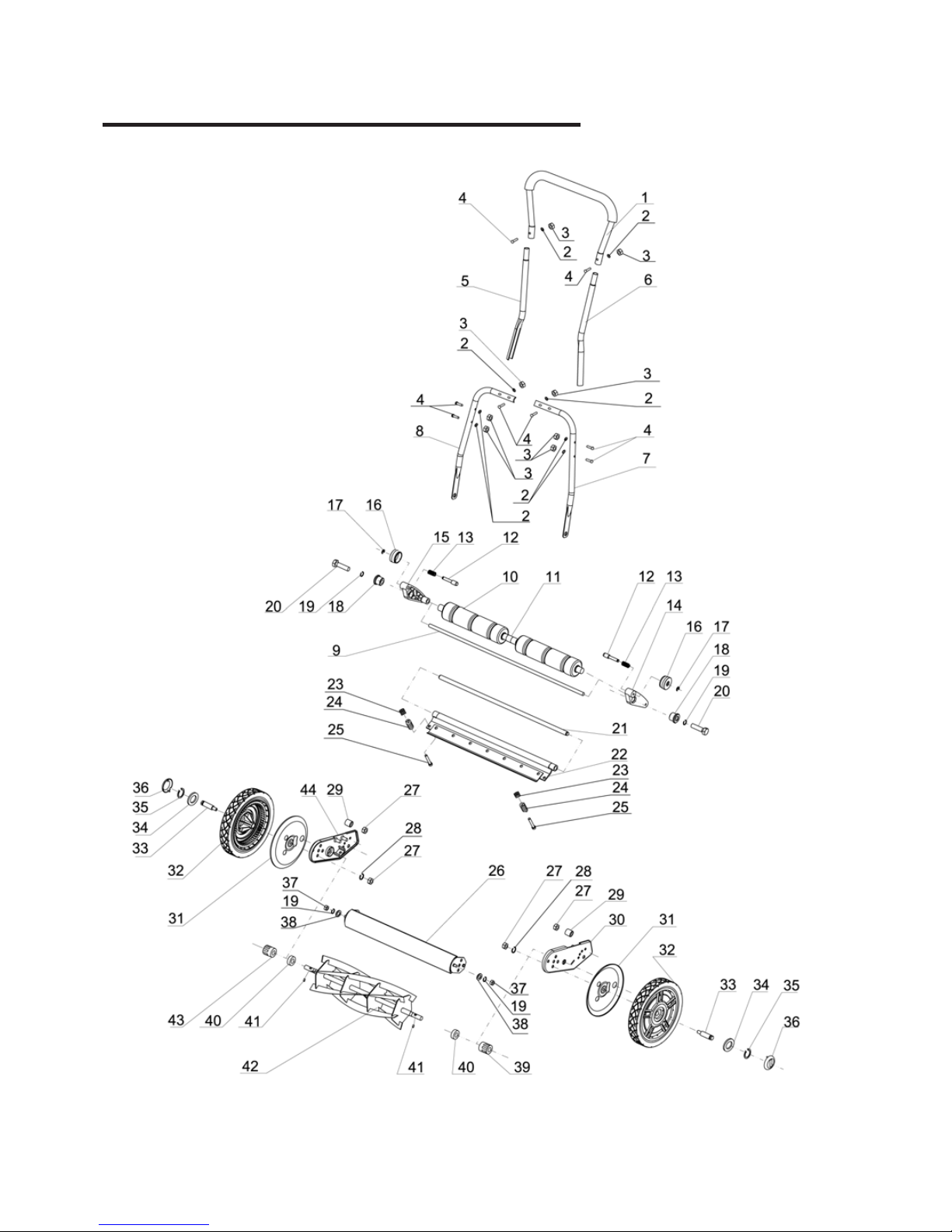
WARRANTY REPLACEMENT PARTS are available by calling the toll free number, 1-866-456-8934
9
8:30 a.m.-5:00 p.m.,EST, Monday-Friday.

PARTS DIAGRAM
10

PARTS DIAGRAM LIST
Item Description Qty
11
1
2
3
4
5
6
7
8
9
10
11
12
13
14
15
16
17
18
19
20
21
22
23
24
25
26
27
28
29
30
31
32
33
34
35
36
37
38
39
40
41
42
43
44
Top handle
Washer Ø6
Locknuts 1/4 X 20
Carriage Bolts 1/4 X 1-3/8’’
Middle handle(R)
Middle handle(L)
Bottom handle(L)
Bottom handle(R)
Roller shaft
Roller
Roller spacer
Height adjustment pin
Height adjustment bracket (L)
Height adjustment bracket (R)
Spring
Height adjustment knob
C-clip
Sleeve
Spring washer Ø8
Hex. Bolt M8X30
Cutting bar pivot rod
Cutting bar assembly
Blade adjustment nut M8
Blade adjustment Spring
Blade adjustment bolt
Housing
Nut M10
Spring washer Ø10
Rubber bomper
Support (L)
Wheel support board
Wheel
Wheel shaft
Washer Ø16
C-clip for shaft
Wheel cover
Nut M8
Washer Ø8
Gear(L)
Ball bearing 6002RS
Pin
Reel cylinder
Gear(R)
Support (R)
1
8
8
8
1
1
1
1
2
2
2
2
1
1
2
2
2
2
2
1
1
2
2
2
1
2
2
2
1
2
2
2
2
2
2
2
2
1
2
2
1
1
1
1
Table of contents
Other Dura-Max Lawn Mower manuals