Durapac HP-35A User manual

ABSOLUTE EQUIPMENT PTY LTD –2/186 Granite Street, GEEBUNG QLD 4034 –Australia
sales@absoluteequipment.com.au –Phone: +61 7 3865 4006 –Fax: +61 7 3102 6288
Maximum Operating Pressure –360 bar
Instruction Manual
35 Ton H-Frame Press
Model –HP-35A

Instruction Manual
HP-35A Press - V1.0 www.durapac.com Page 2 of 11
This is a safety alert symbol. It is used to alert you to potential personal injury hazards.
Obey all safety messages that follow this symbol to avoid injury or death
1.0 Product Information
DURAPAC –H-Frame Presses are engineered to meet International Standards for Performance and
Safety. The HP-35A model is a 35 ton air and hand press that can operate up to 360 bar. Presses can
exert extremely high forces at moderate hydraulic pump pressure. If you have any questions
concerning how much force is exerted at a given pressure, contact a Durapac representative.
Special skill, knowledge and training may be required for a specific task and the product may not be
suitable for all jobs. The user must ultimately make the decision regarding suitability of the product
for any given task and assume the responsibility of safety for all in the work area. Contact a Durapac
representative if you are unsure of your press’ suitability for a particular application.
2.0 Receiving Instructions
It is recommended prior to use that an inspection be done by qualified personnel and that any
missing or damaged parts, decals, warning/safety labels or signs are replaced with Durapac
authorised replacement parts only. Any press that appears to be damaged in any way, is worn,
leaking or operates abnormally should be removed from service immediately until such time as
repairs can be made. Any press that has been or suspected to have been subject to a shock load
should be removed from service immediately until inspected by a Durapac authorised service centre.
Owners and operators of this equipment should be aware that the use and subsequent repair of this
equipment may require specialised training and knowledge.
Locate the press in an isolated area, or shield the press to minimize danger to others.
Hydraulic pressure can cause materials to break, possibly resulting in personal injury
3.0 Safety
Save these instructions. For your safety, read and understand the information contained within. The
owner and operator should have an understanding of this product and safe operating procedures
before attempting to use this product. Instructions and safety information should be conveyed in the
operator's native language before use of this product is authorised. Make certain that the operator
thoroughly understands the inherent dangers associated with the use and misuse of the product. If
any doubt exists as to the safe and proper use of this product as outlined in this factory authorised
manual, remove from service immediately.
DANGER:
To avoid personal injury keep hands and feet away from work area during operation
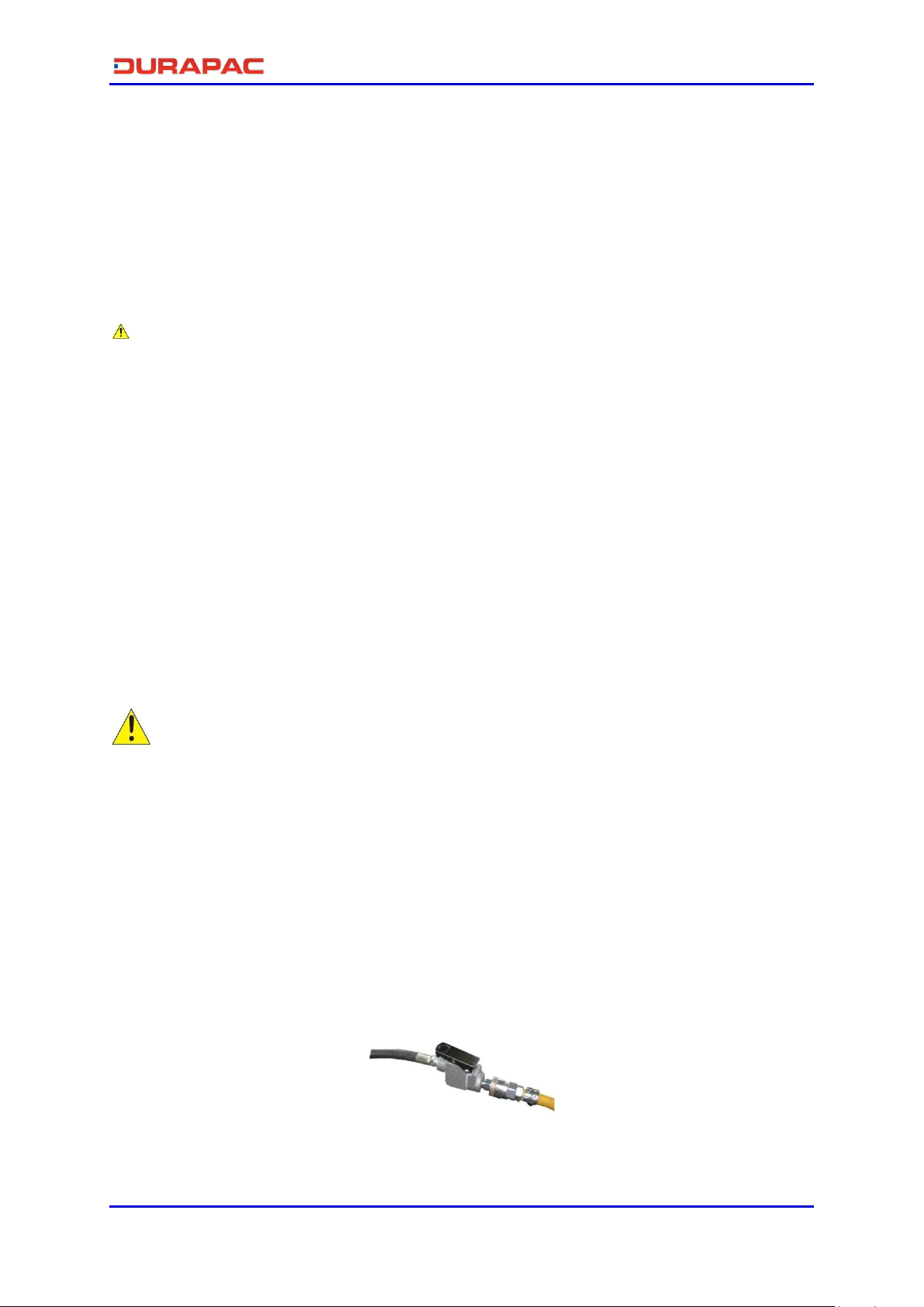
Do NOT handle pressurized hoses. Escaping oil under pressure can penetrate the skin
causing serious injury. If oil is injected under the skin, see a doctor immediately
Stay clear of loads supported by hydraulics. A cylinder, when used as a load lifting
device, should never be used as a load holding device. After the load has been raised
or lowered, it must always be blocked mechanically

Instruction Manual
HP-35A Press - V1.0 www.durapac.com Page 3 of 11
WARNING:
The system operating pressure must not exceed the pressure rating of the lowest
rated component in the system. Install pressure gauges in the system to monitor
operating pressure. It is your window to what is happening in the system
Always wear protective gear when operating hydraulic equipment. The operator must
take precaution against injury due to failure of the tool or work piece(s)
Do NOT hold or stand directly in line with any hydraulic connections while pressurising
Do NOT attempt to disconnect hydraulic connections under pressure. Release all line
pressure before disconnecting hoses
All personnel must be clear before lowering load or depressurising the system
Do NOT attempt to lift a load weighing more than the capacity of the cylinder
IMPORTANT:
If at any stage, the safety related decals become hard to read, these must be replaced
Minimum age of the operator must be 18 years. The operator must have read and
understood all instructions, safety issues, cautions and warnings before starting to
operate the equipment. The operator is responsible for this activity towards other
persons
This device is not suitable for use as a support device! As the system load is lifted, use
blocking and cribbing to guard against a falling load
Do NOT lift hydraulic equipment by the hoses or couplers. Use the carrying handle or
other means of safe transport
Hydraulic equipment must only be serviced by a qualified hydraulic technician. For
repair service, contact the Durapac authorised service centre in your area. To protect
your warranty, use only high quality hydraulic oil
CAUTION:
KEEP HYDRAULIC EQUIPMENT AWAY FROM FLAMES AND HEAT. Hydraulic fluid can
ignite and burn. Excessive heat will soften packings and seals, resulting in fluid leaks.
Heat also weakens hose materials and packings. For optimum performance do not
expose equipment to temperatures of 65°C (150°F) or higher. Protect all equipment
from weld spatter
No alteration should be made to this device
3.1 Hydraulic Presses
To avoid personal injury and possible equipment damage, make sure all hydraulic
components withstand the maximum pressure of 360 bar (5,220psi)
Work pieces must be well supported and aligned so when pressure is exerted;
parts being pressed do not slip out or break
To prevent accidental slippage, do not place work pieces on the press bed, or
apply hydraulic force until all bolster pins are in place and all tension has been
removed from the bolster lift cables
Do NOT overload equipment. Overloading can cause equipment failure and
possible personal injury. The presses are designed for a maximum pressure of 360
bar (5,220psi)
Do NOT stress adapters beyond their capacities. Any pushing or pulling adapters
used with this press must have a maximum tonnage rating equal to, or higher
than, the maximum tonnage rating of the press, or breakage can occur

Instruction Manual
HP-35A Press - V1.0 www.durapac.com Page 4 of 11
It is impossible for Durapac to provide practical “all purpose” shielding because
this is a general all-purpose press that can be used in many different applications.
The owner of the press must supply shielding that is practical and necessary for
each application. Some safety can be provided by wrapping the piece in a
protective blanket before applying pressure
FAILURE TO HEED THESE WARNINGS MAY RESULT IN PERSONAL INJURY AS WELL AS PROPERTY DAMAGE.
4.0 Installation
Do NOT adjust safety valve pressure –safety valve pressure is set at 360 bar (5,220 psi)
4.1 Familiarise yourself with the specifications and illustrations in this owner’s manual.
Know your press, its limitations and how it operates before attempting to use. If in
doubt, contact Durapac.
4.2 Remove all banding from the press and shipping pallet and remove all cartons. Stand
the press upright and attach feet to the press.
4.3 Check all hydraulic connections.
4.4 Check oil level and change drilled bolt to vent cap/plug in the reservoir before
operating the pump.
4.5 Air from the System. Air can accumulate in the hydraulic system during the initial setup
or after prolonged use, causing the cylinder to respond slowly or in an unstable
manner. Should removal of air from pump be required, please follow the steps in 6.2 –
Bleeding Air from the System in the Maintenance Section.
5.0 Operation
IMPORTANT:
It is mandatory that the operator has a full understanding of all instructions, safety
regulations, cautions and warnings, before starting to operate any of this high force
tool equipment
To reduce the risk of personal injury and/or property damage, hydraulic connections
must be securely fastened before building pressure in the system. Release all system
pressure before loosening any hydraulic connection in the system
Always monitor pressure, load or position using suitable equipment. Pressure may be
monitored by means of a manifold and gauge. Correct application position can only be
determined by the operator of the equipment
Do NOT operate the press while the cables are under tension
5.1 Before using - check the air pressure range is between 7-10 kgf/cm2 (Figure 1).
Figure 1

Instruction Manual
HP-35A Press - V1.0 www.durapac.com Page 5 of 11
5.2 Positioning the Work bed:
5.2.1 Lower Bolster (Figure 2):
5.2.1.1 Put a small amount of tension on the cable by cranking the winch
(Figure 3) up, which will then take the weight off the pins. This will
free the pins in the end of the bolster, next to the winch (or the right
hand side of the press). Pull the loose pins out.
Winch
Figure 2 Figure 3
5.2.1.2 Crank the winch, in either direction (up or down) to get movement
of the work bed.
5.2.1.3 When the bolster is in position and the support pins are inserted
completely, turn the winch handle slightly to release the cable.
5.2.2 Upper Bolster (Figure 4):
5.2.2.1 Use the handle to move the plunger left or right.
Figure 4
5.3 Process - If the bolster is at its highest point and the object still
does not reach, use the wheel (Figure 5) to extend the plunger. It
is recommended that the supplied V-Blocks are used to reduce
the distance of the plunger and the object, to avoid putting the
plunger under too much pressure.
Figure 5
5.4 After using –retract plunger completely.
6.0 Maintenance
IMPORTANT:
Use only good quality hydraulic fluid. Never use brake fluid, transmission fluid, turbine
oil, motor oil, alcohol, glycerine etc. Use of anything other than good quality hydraulic
oil will void warranty and damage the press. We recommend Durapac Hydraulic Oil or
equivalent
Equipment must only be serviced by a qualified hydraulic technician. For repair service,
contact your local Durapac authorised service centre
Do NOT exceed oil temperature above 60oC
Keep all hydraulic components clean

Instruction Manual
HP-35A Press - V1.0 www.durapac.com Page 6 of 11
Inspect hoses and connections daily. Replace damaged components immediately
Cables must run on the pulleys easily, and the pulleys must be free to turn. Careful
cable maintenance will help prevent cable breakage
Maintenance is required when wear or leakage is noticed. Periodically inspect all components to
detect any problem that may require service and maintenance
6.1 Adding Hydraulic Fluid
Check oil level regularly.
WARNING: Always add oil with cylinders fully retracted (or extended, if pull cylinders) or
the system will contain more oil than the reservoir can hold
6.1.1 Depressurise and disconnect hydraulic hose from application/cylinder.
6.1.2 Remove plug/bolt(3) and o-ring (2) from the tank assembly (1) Please refer
to 8.2 –Oil Tank/Path Assembly in the Parts Breakdown and List Section for
the part illustrations and corresponding numbers.
6.1.3 Use a small funnel to fill the oil to 20mm from the top of the tank.
6.1.4 Wipe up any spilled fluid and reinstall oil plug.
6.2 Bleeding Air from the System
6.2.1 Repeat all the steps shown in 6.1 –Adding Hydraulic Fluid (above).
6.2.2 Extend and retract the cylinder several times without putting a load on the
system. Air will be released into the pump reservoir.

Instruction Manual
HP-35A Press - V1.0 www.durapac.com Page 7 of 11
7.0 Troubleshooting
Problem
Cause
Solution
Cylinder moves but does not
maintain pressure
Leaking connection
Clean, reseal with thread
sealant and tighten
connection
Leaking cylinder seals
Replace worn seals
Check for excessive
contamination or wear
Replace contaminated fluid as
necessary
Pump/valve malfunctioning
Check pump or valve
operating instructions
Cylinder leaks hydraulic fluid
Worn or damaged seals
Replace worn seals
Check for excessive
contamination or wear
Replace contaminated fluid as
necessary
Loose connections
Clean, reseal with thread
sealant and tighten
connection
Cylinder will not retract or
retracts slower than normal
Closed pump release valve
Open pump release valve
Loose couplers
Tighten couplers
Blocked hydraulic lines
Clean and flush
Weak or broken retraction springs
Send to service centre for
repair
Internally damaged cylinder
Send to service centre for
repair
Pump reservoir too full
Drain hydraulic fluid to
correct level
Erratic Action
Air in the system or pump
cavitation
Add fluid, bleed air and check
for leaks as described in the
Maintenance Section
External leakage
Replace worn packings
Check for excessive
contamination fluid as
necessary
Sticking or binding cylinder
Check for dirt or leaks
Check for bent, misaligned,
worn parts or defective
packings
Cylinder does not move
Loose couplers
Tighten couplers
Faulty coupler
Verify that female coupler is
not locked up (ball wedged
into seat)
Replace both male and female
couplers
Improper valve position
Close release valve or shift to
new position
Low or no hydraulic fluid in pump
reservoir
Fill and bleed the system as
described in the Maintenance
Section

Instruction Manual
HP-35A Press - V1.0 www.durapac.com Page 8 of 11
Problem
Cause
Solution
Air-locked pump
Prime pump as described in
6.2 –Bleeding Air from the
System in the Maintenance
Section
Pump not operating
Check the Operation Section
for the pump’s operating
instructions
Load is above the capacity of the
system
Use the correct equipment
Cylinder extends only partially
Low or no hydraulic fluid in pump
reservoir
Fill and bleed the system as
described in the Maintenance
Section
Load is above the capacity of the
system
Use the correct equipment
Sticking or binding cylinder
Check for dirt or leaks
Check for bent, misaligned,
worn parts or defective
packings
Cylinder moves slower than
normal
Loose couplers
Tighten couplers
Restricted hydraulic line or fitting
Clean and replace if damaged
Pump not operating correctly
Check the Operation Section
for the pump’s operation
instructions
Leaking cylinder seals
Replace worn seals
Check for excessive
contamination or wear
Replace contaminated fluid as
necessary

Instruction Manual
HP-35A Press - V1.0 www.durapac.com Page 9 of 11
8.0 Parts Breakdown and List
8.1 Lower Bolster Assembly
8.2 Oil Tank/Path Assembly
Item Description Qty
1 Lower Bolster - Front 1
2 Lower Bolster - Back 1
3 Lower Stud 4
4 Nut 8
5 Reel 1
6 Frong Bush - Long 1
7 Cable Wire Wheel 2
8 Bolt 2
9 Cable Wire Winch 1
10 Back Bush - Short 1
11 Nut 2
12 Bolt 2
13 Up / Down Adjust Bar 1
14 Fix Plate 1
15 Ohm Bar 1
16 Bolt 2
17 Ohm Gear 1
18 Bolt 2
Item Description Qty
1 Tank Assembly 1
2 O - Ring 1
3 Bolt 1
4 Bolt 2
5 Nut 2
6 Oil Path Assembly 1
7 Handle Insert 1
8 Insert Long Plug 2
9 C - Ring 5
10 Shaft 1
11 Strut Plate 1
12 Back - Up Ring 2
13 O - Ring 2
14 Steel Ball 2
15 Channel Spring 2
16 Inlet Bolt 2
17 O - Ring 1
18 Release Valve Bolt 1
19 Release Valve Button 1
20 Spring Plug 1
21 Bolt 4
22 U - Plate 1
23 Plug 1

Instruction Manual
HP-35A Press - V1.0 www.durapac.com Page 10 of 11
8.3 Hydraulic System
Item Description Qty
1 Cylinder Base 1
2 Cylinder 1
3 Plunger 1
4 O-Ring 1
5 Back-Up Ring 1
6 Piston 1
7 Back-Up Ring 2
8 O-Ring 2
9 O-Ring 1
10 Lower Screw 1
11 O-Ring 1
12 Bolt 4
13 Bolt 4
14 Wheel Fixing 2
15 Wheel 1
16 Spiral Bar 1
17 Bolt 1
18 Spring Plug 1
19 O-Ring 1
20 Saddle 1
21 Bolt 2
22 U Fixing 2
23 Bolt 4
24 Nut 4
25 Bolt 2
26 Up - Plate 1
27 Roller 4
28 Bolt 4
29 S - Spring 2
30 Gauge Accessory 1
31 Street Elbow 1
32 Coupling 1
33 Pressure Gauge 1

Instruction Manual
HP-35A Press - V1.0 www.durapac.com Page 11 of 11
8.4 Frame
Items marked with a * are contained within the standard Repair Kit - Serial number and model number
need to be quoted when ordering parts.
Item Description Qty
1 Upper Bolster - Front 1
2 Upper Stud (M20*290) 3
3 Upper Bolster - Back 1
4 Nut 11
5 Spiral Bar 1
6 Bolt 4
7 Fix Block 20 1
8 Spiral Nut Assembly 1
9 Fix Block 16 1
10 Nut 1
11 Low Bolster Assembly 1
12 Fix Pin 2
13 Frame 4
14 Bolt 4
15 Internal Thread Bar 4
16 Bolt 4
17 Small Angle Steel 1
18 Bolt 4
19 Frame Plate 2
20 Big Angle Steel 2
21 Nut 8
22 Bolt 8
23 Upper Stud 2
24
Upper Stud (M20 one line thread) 1
Table of contents
Other Durapac Power Tools manuals
Popular Power Tools manuals by other brands

Würth
Würth AKP 12 COMPACT Translation of the original operating instructions

Stanley
Stanley EB35PB user manual

GMC
GMC R1020 instruction manual

Makita
Makita DHR243Y1J instruction manual

Drill Master
Drill Master Drill Doctor 500X user guide

Gude
Gude GDS 16 PRO Translation of original operating instructions