Durapac HP-10 User manual

ABSOLUTE EQUIPMENT PTY LTD –2/186 Granite Street, GEEBUNG QLD 4034 –Australia
sales@absoluteequipment.com.au –Phone: +61 7 3865 4006 –Fax: +61 7 3102 6288
Maximum Operating Pressure –700 bar
Instruction Manual
10 Ton Hydraulic Bench Press
Model –HP-10

Instruction Manual
HP-10 Bench Press - V1.4 www.durapac.com Page 2 of 13
This is a safety alert symbol. It is used to alert you to potential personal injury hazards.
Obey all safety messages that follow this symbol to avoid injury or death
1.0 Product Information
DURAPAC –Hydraulic Bench Presses are engineered to meet Industrial Standards for Performance
and Safety. The HP-10 unit incorporates a two speed hydraulic hand pump with force gauge, hose
and a 10 ton 152 mm stroke spring return cylinder. The HP-10 bench press is ideal for workshop
pressing jobs such as the installation or removal of bearings and gears, repair of electric motors or
other press fit parts.
10 ton hydraulic cylinder with 152 mm stroke. Longer stroke cylinders available on request
Press plate set and bushing allows for greater pressing flexibility
Steel frame provides maximum strength and rigidity
Press bed has multiple working positions
2 speed hand pump with force gauge and 2 metre hose set
Note –DPR-15R air/hydraulic power unit with remote pendant can also be used to operate the HP-
10 press.
Special skill, knowledge and training may be required for a specific task and the product may not be
suitable for all jobs. The user must ultimately make the decision regarding suitability of the product
for any given task and assume the responsibility of safety for all in the work area. Contact a Durapac
representative if you are unsure of your bench press’ suitability for a particular application.
2.0 Receiving Instructions
It is recommended prior to use that an inspection be done by qualified personnel and that any
missing or damaged parts, decals, warning/safety labels or signs are replaced with Durapac
authorised replacement parts only. Any bench press that appears to be damaged in any way, is
worn, leaking or operates abnormally should be removed from service immediately until such time
as repairs can be made. Any bench press that has been or suspected to have been subject to a shock
load should be removed from service immediately until inspected by a Durapac authorised service
centre. Owners and operators of this equipment should be aware that the use and subsequent
repair of this equipment may require specialised training and knowledge.
3.0 Safety
Save these instructions. For your safety, read and understand the information contained within. The
owner and operator should have an understanding of this product and safe operating procedures
before attempting to use this product. Instructions and safety information should be conveyed in the
operator's native language before use of this product is authorised. Make certain that the operator
thoroughly understands the inherent dangers associated with the use and misuse of the product. If
any doubt exists as to the safe and proper use of this product as outlined in this factory authorised
manual, remove from service immediately.
DANGER:
To avoid personal injury keep hands and feet away from work area during operation

Instruction Manual
HP-10 Bench Press - V1.4 www.durapac.com Page 3 of 13
Do NOT handle pressurised hoses. Escaping oil under pressure can penetrate the skin
causing serious injury. If oil is injected under the skin, see a doctor immediately
Stay clear of loads supported by hydraulics. A cylinder, when used as a load lifting
device, should never be used as a load holding device. After the load has been raised
or lowered, it must always be supported mechanically
WARNING:
The system operating pressure must not exceed the pressure rating of the lowest
rated component in the system. Install pressure gauges in the system to monitor
operating pressure. It is your window to what is happening in the system
Always wear appropriate personal protective equipment (PPE) when operating
hydraulic equipment. The operator must take precaution against injury due to failure
of the tool or work piece(s)
Do NOT hold or stand directly in line with any hydraulic connections while pressurising
Do NOT attempt to disconnect hydraulic connections under pressure. Release all line
pressure before disconnecting hoses
All personnel must be clear before lowering load or depressurising the system
Do NOT attempt to lift a load weighing more than the capacity of the cylinder
IMPORTANT:
If at any stage, the safety related decals become hard to read, these must be replaced
Minimum age of the operator must be 18 years. The operator must have read and
understood all instructions, safety issues, cautions and warnings before starting to
operate the equipment. The operator is responsible for this activity towards other
persons
Do NOT lift hydraulic equipment by the hoses or couplers. Use the carrying handle or
other means of safe transport
Hydraulic equipment must only be serviced by a qualified hydraulic technician. For
repair service, contact the Durapac authorised service centre in your area. To protect
your warranty, use only high quality hydraulic oil
CAUTION:
KEEP HYDRAULIC EQUIPMENT AWAY FROM FLAMES AND HEAT. Hydraulic fluid can
ignite and burn. Excessive heat will soften packings and seals, resulting in fluid leaks.
Heat also weakens hose materials and packings. For optimum performance do not
expose equipment to temperatures of 65°C (150°F) or higher. Protect all equipment
from weld spatter
No alteration should be made to this device
3.1 Hydraulic Presses
Work pieces must be well supported and aligned so when pressure is exerted; parts
being pressed do not slip out or break

Instruction Manual
HP-10 Bench Press - V1.4 www.durapac.com Page 4 of 13
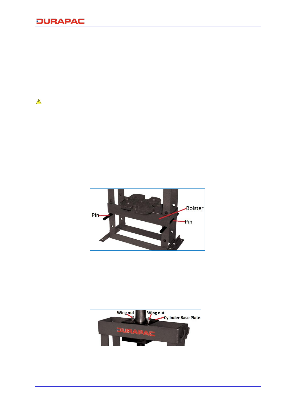
To prevent accidental slippage, do not place work pieces on the press bed, or apply
hydraulic force until all bolster pins are in place and all tension has been removed
from the bolster lift cables
Do NOT overload equipment. Overloading can cause equipment failure and possible
personal injury. The presses are designed for a maximum pressure of 700 bar
Do NOT stress adapters beyond their capacities. Any pushing or pulling adapters used
with this press must have a maximum tonnage rating equal to, or higher than, the
maximum tonnage rating of the press, or breakage can occur
It is impossible for Durapac to provide practical “all purpose” shielding because this is
a general all-purpose press that can be used in many different applications. The owner
of the press must supply shielding that is practical and necessary for each application.
Some safety can be provided by wrapping the piece in a protective blanket before
applying pressure
3.2 Hydraulic Hoses & Fluid Transmission Lines
Avoid short runs of straight line tubing. Straight line runs do not provide for
expansion and contraction due to pressure and/or temperature changes
Reduce stress in tube lines. Long tubing runs should be supported by brackets or
clips. Before operating the pump, connections should be tightened securely and
leak-free. Over tightening can cause premature thread failure or high pressure
fittings to burst
Should a hydraulic hose ever rupture, burst or need to be disconnected,
immediately shut off the pump and release all pressure. Never attempt to grasp a
leaking pressurised hose with your hands. The force of escaping hydraulic fluid can
inflict injury
Do NOT subject the hose to potential hazard such as fire, sharp objects, extreme
heat or cold or heavy impact
Do NOT allow the hose to kink, twist, curl, crush, cut or bend so tightly that the fluid
flow within the hose is blocked or reduced. Periodically inspect the hose for wear
Hose material and coupler seals must be compatible with the hydraulic fluid used.
Hoses also must not come in contact with corrosive materials such as battery acid,
creosote-impregnated objects and wet paint. Never paint a coupler or hose
FAILURE TO HEED THESE WARNINGS MAY RESULT IN PERSONAL INJURY AS WELL AS PROPERTY DAMAGE.
4.0 Installation
Locate the press in an isolated area, or shield the press to minimize danger to others. Hydraulic
pressure can cause materials to break, possibly resulting in personal injury
Do NOT adjust safety valve pressure –safety valve pressure is set at 700 bar
4.1 Familiarise yourself with the details and illustrations in this owner’s manual. Know your
bench press, its limitations and how it operates before attempting to use. If in doubt,
contact a Durapac representative.

Instruction Manual
HP-10 Bench Press - V1.4 www.durapac.com Page 5 of 13
4.2 Check all system fittings and connections to be sure they are tight and leak free.
4.3 Check oil level in reservoir before operating pump.
4.4 Remove air from the system –Air can accumulate in the hydraulic system during the
initial setup or after prolonged use, causing the cylinder to respond slowly or in an
unstable manner. Should removal of air from pump be required, please follow the
steps in 6.2 –Bleeding Air from the System in the Maintenance Section.
5.0 Operation
Presses can exert extremely high forces at moderate hydraulic pump pressure. Ensure the
included force gauge is closely monitored during all pressing operations
5.1 Positioning the Work bed
5.1.1 Vertical Positioning of the Bolster:
5.1.1.1 Manually support the bolster.
5.1.1.2 Remove pins from frame.
5.1.1.3 Lift or lower bolster until desired position has been reached.
5.1.1.4 Reinsert pins into frame.
Figure 1 –Vertical Positioning
5.1.2 Horizontal Positioning of the Cylinder:
5.1.2.1 Undo wing nuts on the cylinder base plate, slide left or right to
adjust position.
5.1.2.2 Tighten wing nuts once desired position has been reached.
Figure 2 –Positioning the Cylinder Base

Instruction Manual
HP-10 Bench Press - V1.4 www.durapac.com Page 6 of 13
5.2 Pump operation
IMPORTANT:
Do NOT add extensions to the pump handle. Extensions cause unstable pump
operation
In certain situations the pump handle can "kick back". Always keep your body to the
side of the pump, away from the line of force of the handle
Do NOT operate a pump that is disconnected from application. If operated in this
condition, the hose and connections will become pressurised. This increases burst
hazard. Damage may occur to pump and its components
The pump may be operated in a horizontal or in a vertical position with the head pointing
down as shown.
Figure 3 –Hand Pump Operation
5.2.1 Before Using the Pump
5.2.1.1 Check all system fittings and connections to be sure they are tight
and leak free.
5.2.1.2 Check oil level in reservoir before operating pump.
5.2.2 Using a Two-Speed Pump
This pump provides 2-stage flow. Under no-load, the pump operates in the
high flow first stage for rapid advance. When the load is contacted, the
pump automatically shifts to the second stage for building pressure. After
the pump shifts, pumping takes less effort.
Note: To reduce handle effort at high pressure, take short strokes.
Maximum leverage is obtained in the last 5° of stroke. For best
performance, operate pump handle at moderate speed during the high flow
first stage. Rapid handle speed in the first stage will prevent the pump from
delivering full volume of oil.
5.2.3 Advance and Retraction of Single-Acting Applications
5.2.3.1 Turn the pump’s release valve clockwise to a closed position.
IMPORTANT: Only hand tighten the valve. Applying too much force to
the valve may damage the valve stem.

Instruction Manual
HP-10 Bench Press - V1.4 www.durapac.com Page 7 of 13
5.2.3.2 Work the pump handle up and down to send oil through the hose to
the cylinder, causing the piston to extend to the work piece.
5.2.3.3 Monitor the pressure gauge while completing the application.
Note: The pump is equipped with an overload valve that will bypass oil back
into the pump reservoir in an overload situation (when the system meets
maximum pressure). In this case, continued pumping will have no effect on
the system. If an overload situation commonly occurs, a higher capacity set
is needed.
5.2.3.4 To release pressure, slowly turn the release valve counter clockwise.
The release speed is controlled by how fast the valve is opened.
5.2.4 Relief Valve Adjustment
All pumps contain a factory set relief valve to prevent over-pressurisation of
the system.
6.0 Maintenance
IMPORTANT:
Check oil level regularly
Use only good quality hydraulic fluid. Do NOT use brake fluid, transmission fluid,
turbine oil, motor oil, alcohol, glycerine etc. Use of anything other than good quality
hydraulic oil will void warranty and damage the press. We recommend Durapac
Hydraulic Oil or equivalent
Cables must run on the pulleys easily, and the pulleys must be free to turn. Careful
cable maintenance will help prevent cable breakage
Maintenance is required when wear or leakage is noticed. Periodically inspect all
components to detect any problem that may require service and maintenance.
6.1 Adding Hydraulic Fluid
WARNING: Always add oil with cylinders fully retracted (or extended, if pull cylinders) or
the system will contain more oil than the reservoir can hold
6.1.1 Depressurise and disconnect hydraulic hose from application/cylinder.
6.1.2 Put the pump in a vertical position (pump head face down); remove oil filler
plug located on rear of the pump reservoir.
6.1.3 Use a small funnel to fill the reservoir to approximately 75 mm from the top of
the oil filler hole.
6.1.4 Bleed air from system if necessary.
6.1.5 Wipe up any spilled fluid and reinstall the air vent plug/reservoir cap.

Instruction Manual
HP-10 Bench Press - V1.4 www.durapac.com Page 8 of 13
6.2 Bleeding Air from the System
6.2.1 Repeat Steps 6.1.1 to 6.1.3 (above), if required.
6.2.2 Invert cylinder and place at a lower level than the pump reservoir.
6.2.3 Extend and retract the cylinder several times without putting a load on the
system. Air will be released into the pump reservoir.
6.2.4 Recheck oil level after removing air.
6.3 Changing Hydraulic Fluid
For best results, change fluid once a year or every 300 hours of use
6.3.1 Repeat Steps 6.1.1 to 6.1.2 (above).
6.3.2 Pour used fluid into a sealable container.
6.3.3 Repeat Steps 6.1.3 to 6.1.5 (above).
6.3.4 Dispose of fluid in accordance with local regulations.
6.4 Lubrication
To extend pump life and improve performance, lubricate the beam pin (A), cross pin
(B), and piston head (C) regularly, using roller bearing grease.
Figure 4 - Lubrication
6.5 Storage
6.5.1 When not in use, depressurise and disconnect the hydraulic pump from the
application.
6.5.2 Wipe clean thoroughly and store in a clean, dry environment. Avoid
temperature extremes.
6.5.3 Shield pump with a protective cover.

Instruction Manual
HP-10 Bench Press - V1.4 www.durapac.com Page 9 of 13
7.0 Troubleshooting
Problem
Cause
Solution
Cylinder moves but does not
maintain pressure
Leaking connection
Clean, reseal with thread
sealant and tighten
connection
Leaking cylinder seals
Replace worn seals
Check for excessive
contamination or wear
Replace contaminated fluid
as necessary
Pump/valve malfunctioning
Check pump or valve
operating instructions
Pump does not reach rated
capacity
Low fluid level in reservoir
Check fluid level
Leaking system components
Repair or replace as
necessary
Fluid leaking past inlet or outlet
checks
Repair inlet or outlet
checks
Replace high pressure
piston seal
Pump handle has a “spongy”
feel
Air trapped in system
Refer to 6.2 –Bleeding Air
from the System
Too much fluid in reservoir
Check fluid level
Cylinder leaks hydraulic fluid
Worn or damaged seals
Replace worn seals
Check for excessive
contamination or wear
Replace contaminated fluid
as necessary
Loose connections
Clean, reseal with thread
sealant and tighten
connection
Cylinder will not retract or
retracts slower than normal
Closed pump release valve
Open pump release valve
Loose couplers
Tighten couplers
Blocked hydraulic lines
Clean and flush lines
Weak or broken retraction
springs
Send to a Durapac
authorised service centre
for repair
Internally damaged cylinder
Send to a Durapac
authorised service centre
for repair
Pump reservoir too full
Drain hydraulic fluid to
correct level
Low fluid level in pump
reservoir
Fill and bleed the system as
described in the
Maintenance Section
Erratic Action
Air in the system or pump
cavitation
Add fluid, bleed air and
check for leaks as
described in the
Maintenance Section

Instruction Manual
HP-10 Bench Press - V1.4 www.durapac.com Page 10 of 13
Problem
Cause
Solution
External leakage
Replace worn packings
Check for excessive
contamination fluid as
necessary
Sticking or binding cylinder
Check for dirt or leaks
Check for bent, misaligned,
worn parts or defective
packings
Cylinder does not move
Loose couplers
Tighten couplers
Faulty coupler
Verify that female coupler
is not locked up (ball
wedged into seat)
Replace both male and
female couplers
Improper valve position
Close release valve or shift
to new position
Low or no hydraulic fluid in
pump reservoir
Fill and bleed the system as
described in the
Maintenance Section
Air-locked pump
Prime pump as described in
6.2 –Bleeding Air from the
System in the Maintenance
Section
Pump not operating
Check the Operation
Section for the pump’s
operating instructions
Load is above the capacity of
the system
Use the correct equipment
Cylinder extends only partially
Low or no hydraulic fluid in
pump reservoir
Fill and bleed the system as
described in the
Maintenance Section
Load is above the capacity of
the system
Use the correct equipment
Sticking or binding cylinder
Check for dirt or leaks
Check for bent, misaligned,
worn parts or defective
packings
Cylinder moves slower than
normal
Loose couplers
Tighten couplers
Restricted hydraulic line or
fitting
Clean and replace if
damaged
Pump not operating correctly
Check the Operation
Section for the pump’s
operation instructions
Leaking cylinder seals
Replace worn seals
Check for excessive
contamination or wear
Replace contaminated fluid
as necessary

Instruction Manual
HP-10 Bench Press - V1.4 www.durapac.com Page 11 of 13
8.0 Parts Breakdown and List
8.1 Hydraulic Press Assembly
Item
Description Part No. Qty Item Description Part No. Qty
1 Frame assembly ZAL1475 1 12 Bolster ZAL1486 1
2 Upper cylinder fixed base ZAL1476 1 13 Hydraulic cylinder HP-10R 1
3 Lower cylinder fixed base ZAL1477 1 14 Hand pump P-260 1
4 Screw ZAL1478 2 15 Gauge adapter FGA-1 1
5 Washer ZAL1479 2 16 Quick coupler ZAL1487 1
6 Wing nut ZAL1480 2 17 Quick coupler ZAL1488 1
7 Frame feet ZAL1481 2 18 Gauge ZAL1403 1
8 Screw ZAL1482 4 19 Hose ZAL1326 1
9 Spring washer ZAL1483 4 20 Reaction plate ZAL1491 1
10 Nut ZAL1484 4 21 Load cap ZAL1490 1
11 Pin ZAL1485 2 Reaction plate & load cap set ZAL1489 1

Instruction Manual
HP-10 Bench Press - V1.4 www.durapac.com Page 12 of 13
8.2 Pump Assembly –Model P-260 ***Supersedes all previous versions***
Item Description Part No. Qty Item Description Part No. Qty Item Description Part No. Qty
1 Pump housing ZAL1010 1 15 L.P. piston ZAL1103 1 28 Valve cover screw ZAL1286 2
2 O-ring* ZAL1210 1 16 Yoke ZAL1176 1 29 Steel ball ZAL1370 2
3 Air release screw ZAL1285 1 17 Piston pin ZAL1108 1 30 Spring end cap ZAL1096 2
4 Steel ball ZAL1366 4 18 Yoke pin ZAL1095 1 31 L.P. spring ZAL1350 1
5 Screw ZAL1284 3 19 Retaining ring ZAL1327 1 32 Screw ZAL1175 2
6 O-ring ZAL1229 1 20 Yoke cover ZAL1226 1 33 Set screw ZAL1294 2
7 Nipple ZAL1264 1 21 Handle ZAL1066 1 34 H.P. spring ZAL1346 1
8 Set screw ZAL1297 1 22 Handle grip ZAL1263 1 35 Oil seal ZAL1224 1
9 O-ring* ZAL1272 1 23 Steel ball ZAL1367 2 36 Washer ZAL1351 1
10 Back-up ring* ZAL1209 1 24 Spring ZAL1344 2 37 Release nut ZAL1291 1
11 H.P. piston ZAL1406 1 25 Steel ball ZAL1368 2 38 Release valve screw ZAL1292 1
12 Snap ring ZAL1329 1 26 Spring ZAL1339 2 39 Release valve ZAL1388 1
13 O-ring* ZAL1277 1 27 Washer ZAL1340 2 40 Screw ZAL1290 1
14 Back-up ring* ZAL1225 1 Repair kit ZAL1396 1

Instruction Manual
HP-10 Bench Press - V1.4 www.durapac.com Page 13 of 13
Items marked with a * are contained within a standard Repair Kit.
Serial number, model and part number need to be quoted when ordering parts.
8.3 Cylinder –Model HP-10R
Item Description Part No. Qty Item Description Part No. Qty
1 Cylinder base ZAL1455 1 12 Spring ring ZAL1465 1
2 O-ring* ZAL1456 1 13 Piston rod ZAL1466 1
3 Cylinder ZAL1457 1 14 Spring ring ZAL1467 1
4 Screw ZAL1458 1 15 Fasten nut ZAL1468 1
5 Spring ZAL1459 1 16 Cylinder sleeve ZAL1469 1
6 Nut ZAL1460 1 17 Spacer ZAL1470 1
7 Snap ring ZAL1328 1 18 Pin ZAL1471 1
8 Washer ZAL1461 1 19 Coupler ZAL1472 1
9 U-cup seal* ZAL1462 1 20 Set screw ZAL1297 1
10 Back-up ring* ZAL1463 1 Repair kit ZAL1474 1
11 Brass bushing ZAL1464 1
Table of contents
Other Durapac Power Tools manuals