DURASTAR.COM
4
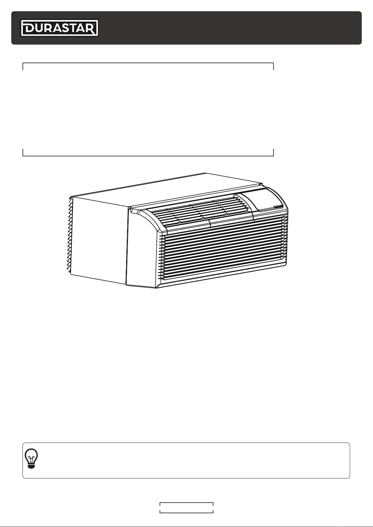
IMPORTANT SAFETY PRECAUTIONS
Improper handling can cause serious damage or injury. Please read the following safety
information in its entirety.
Operation, Cleaning, and Maintenance Safety Precautions
• Children and people with reduced physical, sensory, or mental capabilities, or lack of
experience and knowledge, should only use this air conditioner if they are given supervision or
instructions concerning use of the air conditioner in a safe way and understand the hazards
involved.
• Children should not play with the air conditioner.
• Never stick fingers or any other body parts into the air conditioner openings. The internal fan
may be rotating at high speeds, and may result in injury.
• After removing the filter, do not touch the fins in order to avoid injury.
• Maintenance must be performed by qualified professionals. Otherwise, you may experience
personal injury or damage to the air conditioner and surrounding property.
• Do not repair the air conditioner by yourself. It may cause electric shock or damage. Please
contact a qualified service representative when you need to repair the air conditioner.
• Do not block the air outlet or air inlet. This could cause a malfunction.
• If the below problems occur, please turn off the air conditioner and disconnect power at the
circuit breaker immediately. Then contact your dealer or a qualified professional for service.
• The power cord is overheating or damaged.
• There is an abnormal sound during operation.
• The circuit breaker trips frequently.
• The air conditioner gives off a burning smell.
• The indoor unit is leaking.
• If the air conditioner operates under abnormal conditions, it may cause malfunctions, electric
shock, or fire hazard.
• Do not step on the top panel of the unit, or put heavy objects on the top panel. This could
cause damage or personal injury.
• Cleaning and user maintenance should not be performed by children without supervision.
• Do not spray water on the indoor unit. This could cause electric shock or a unit malfunction.
• Do not use flammable materials such as hair spray, lacquer, or paint near the air conditioner as
they may catch fire.
• Do not operate the air conditioner in places near combustible gases. Emitted gases may
collect around the air conditioner and cause an explosion.
• Do not use fire or a hair dryer to dry the filter. This could cause a deformation or fire hazard.
• Do not wash the air conditioner with water as this could cause an electric shock.
• Disconnect the power supply by turning it off at the circuit breaker when cleaning the air
conditioner. Otherwise, you could risk electric shock.