3.INSTALLATION AND CONNECTION
8
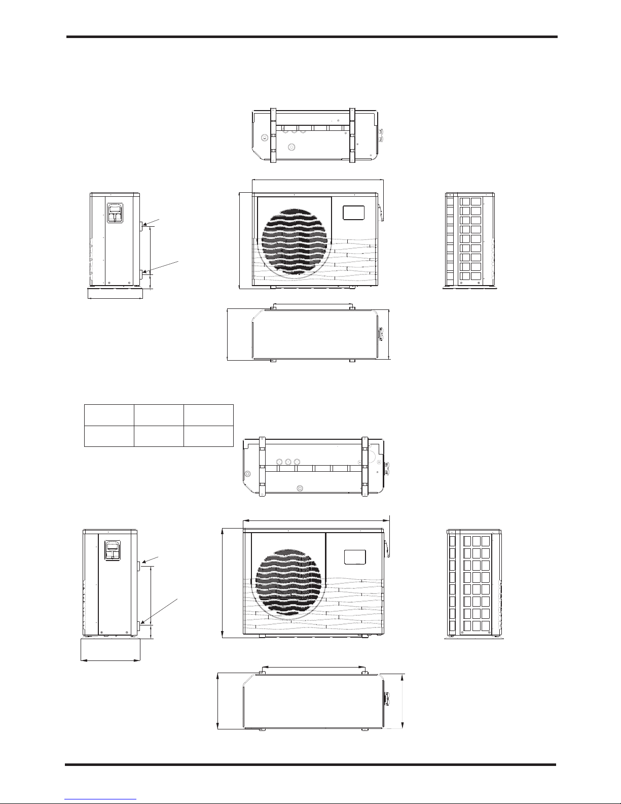
3.4 Swimming Pool Heat Pumps Plumbing
Location: Connect the unit in the pool pump discharge (return) line downstream of all filter
and pool pumps, and upstream of any chlorinators, ozonators or chemical pumps.
Standard model have slip glue fittings which accept 32mm or 50 mm PVC pipe for
connection to the pool or spa filtration piping. By using a 50 NB to 40NB you can plumb 40NB
Give serious consideration to adding a quick coupler fitting at the unit inlet and outlet to allow
easy draining of unit for winterizing and to provide easier access should servicing be
required.
Condensation: Since the Heat pump cools down the air about 4 -5℃, water may condense on
the fins of the horseshoe shaped evaporator. If the relative humidity is very high, this could
be as much as several litres an hour. The water will run down the fins into the basepan and
drain out through the barbed plastic condensation drain fitting on the side of the basepan.
This fitting is designed to accept 20mm clear vinyl tubing which can be pushed on by hand
and run to a suitable drain. It is easy to mistake the condensation for a water leak inside the
unit.
NB: A quick way to verify that the water is condensation is to shut off the unit and keep the
pool pump running. If the water stops running out of the basepan, it is condensation. AN
EVEN QUICKER WAY IS to TEST THE DRAIN WATER FOR CHLORINE - if the is no chlorine
present, then it's condensation.
To pool
From pump
PVC COUPLER
RECOMMENDED(Provided)
CONDENSATION
DRAIN
BARB FTG
The Swimming Pool Heat Pumps exclusive rated flow titanium heat exchanger requires no
special plumbing arrangements except bypass(please set the flow rate according to the
nameplate). The water pressure drop is less than 10kPa at max. Flow rate. Since there is no
residual heat or flame Temperatures, The unit does not need copper heat sink piping. PVC
pipe can be run straight into the unit.
7
3.INSTALLATION AND CONNECTION
The unit will perform well in any outdoor location provided that the following three factors are
presented:
1. Fresh Air - 2. Electricity - 3. Pool filter piping
The unit may be installed virtually anywhere outdoors. For indoor pools please consult the
supplier. Unlike a gas heater, it has no draft or pilot light problem in a windy area.
DO NOT place the unit in an enclosed area with a limited air volume, where the units
discharge air will be re-circulated.
DO NOT place the unit to shrubs which can block air inlet. These locations deny the unit of a
continuous source of fresh air which reduces it efficiency and may prevent adequate heat
delivery.
3.2 Swimming Pool Heat Pumps Location
Normally, the pool heat pump is installed within 7.5 metres of the pool. The longer the
distance from the pool, the greater the heat loss from the piping. For the most part ,the piping
is buried. Therefore, the heat loss is minimal for runs of up to15 meters(15 meters to and from
the pump = 30 meters total), unless the ground is wet or the water table is high. A very rough
estimate of heat loss per 30 meters is 0.6 kW-hour,(2000BTU) for every 5 ℃ difference in
temperature between the pool water and the ground surrounding the pipe, which translates to
about 3% to 5% increase in run time.
3.3 How Close To Your Pool?
Air inlet
Air outlet
300mm
700mm
300mm
500mm
700mm