Led Display Indicators
The following is a list of possible indicators that may appear on the indoor unit's display panel. Not
all the display indicators may be available on the unit purchased.
Feature Indicator Notes
TIMER ON,
SWING, TURBO,
SILENCE
ON Displays for 3 seconds when the TIMER ON feature is set or the
SWING, TURBO, or SILENCE feature is turned on. If the unit is off,
ON will continue to be shown if the TIMER ON feature is set.
TIMER OFF,
SWING, TURBO,
SILENCE
OF Displays for 3 seconds when the TIMER OFF feature is set or the
SWING, TURBO, or SILENCE feature is turned off.
SELF CLEAN SC Displays when the SELF CLEANING feature is on.
FP FP Displays when the FP feature is on.
FORCED
COOLING
FC Displays when the FORCED COOLING mode is selected with the
manual control button. See Manual Operation section.
ANTI-COLD AIR
FLOW
cF The unit is designed not to blow cold air in HEAT mode. When
HEAT mode is selected the unit will display "cF" until the set
temperature is reached and the unit can blow warm air.
DEFROST dF Displays when unit is defrosting. This may last 5-10 minutes
depending on the outdoor temperature and the amount of frost
buildup on the outside unit.
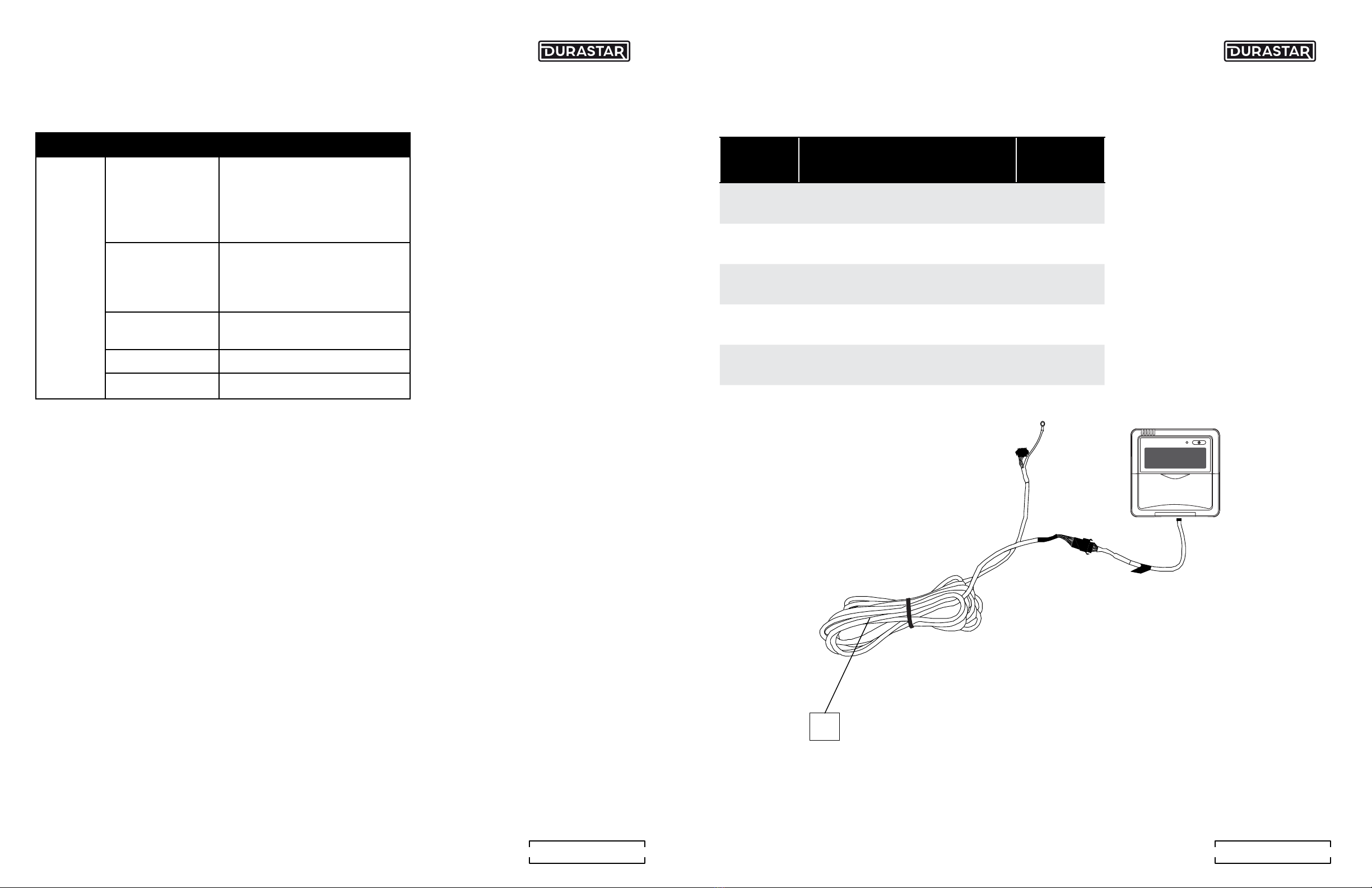
Manual Operation (Use Without Thermostat)
The optional plug-in display control panel DRPDRAD09F1A16 is intended for testing purposes and
emergency operation in cases such as the DRAD units, where the indoor unit does not have its
own manual operation. Please do not use the optional control panel, unless the wired thermostat
is unresponsive and it is absolutely necessary. The unit must be turned off before manual
operation.
To operate your unit manually:
1. Locate the MANUAL button on the optional display panel.
2. Press the MANUAL button one time to activate FORCED AUTO mode.
3. Press the MANUAL button again to activate FORCED COOLING mode.
Panel
MANUAL buton
Optional Display Control Panel
ISSUE POSSIBLE CAUSES
The fan speed cannot
be changed
Check whether Auto mode is
selected.
In AUTO mode, the fan speed is
set automatically and cannot be
changed.
Check whether DRY mode is
selected.
In DRY mode, the FAN SPEED
button is ineffective.
The fan speed can only be changed in
COOL, FAN and HEAT mode.
The temperature display is off. Check whether FAN
mode is selected.
In FAN mode, the temperature
cannot be adjusted.
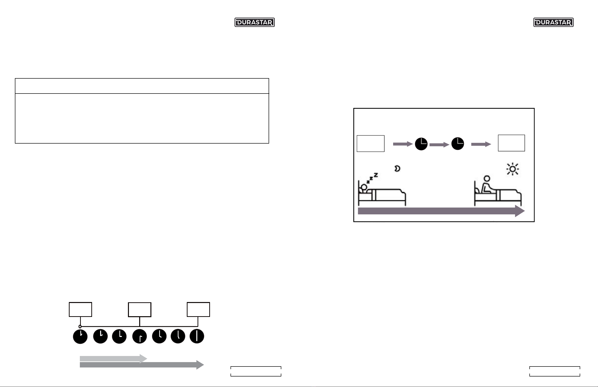
The TIMER OFF disappears
after a period of time.
If the TIMER OFF function
was activated, the operation
may have finished.
The air conditioner will
automatically stop at the set
time and the indicator light will
turn off.
The TIMER ON indicator
disappears after a period of
time.
If the TIMER ON function
was activated,the operation
may have finished.
The air conditioner will
automatically start at the set
time and the indicator light will
turn off.
Unit does not turn on when
pressing ON/OFF button
The unit has a 3-minute protection feature that prevents the unit from
overloading. The unit cannot be restarted within three minutes of being turned
off.
The unit changes from COOL/
HEAT mode to FAN mode
The unit may change its setting to prevent frost from forming on the unit.
Once the temperature increases, the unit will start operating in the previously
selected mode again.
The set temperature has been reached, at which point the unit turns off the
compressor. The unit will continue operating when the temperature fluctuates
again.
Troubleshooting
16 17
D UR A STA R.CO M D UR A STA R.CO M