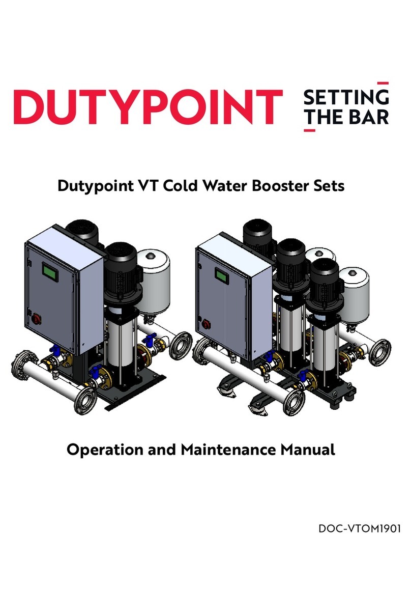
Dutypoint VR2 User manual

VR (VASCO) Cold Water Booster Sets
Operation and Maintenance Manual
DOC-VRVOM1701

Operation and Maintenance Manual
2
Table of Contents
Operation and Maintenance Manual
VR2, VR3 and VR4 Cold Water Booster Sets Equipped with VASCO Inverter Drives
Dutypoint Limited
Shepherd Road
Gloucester
GL2 5EL
United Kingdom
1. Important Safety Information..............................................................................................................................................3
2. Operating Limits........................................................................................................................................................................5
3. VR Booster Set Components.................................................................................................................................................6
4. Control Panel Overview..........................................................................................................................................................7
5. Control Panel Wiring Diagrams...........................................................................................................................................8
6. Commissioning.......................................................................................................................................................................12
7. User Maintenance .................................................................................................................................................................16
8. Operating the Pump Set .....................................................................................................................................................17
9. Pressure Vessel.......................................................................................................................................................................19
10. Troubleshooting ..................................................................................................................................................................21
Appendix A: Lowara e-SV Pumps O&M Manual .............................................................................................................26
Appendix B: VASCO O&M Manual .......................................................................................................................................55

Important Safety Information
3
1 Important Safety Information
1.1 Health & Safety at Work Act 1974
Section 6(a) of this Act requires manufacturers to advise their customers on the safety and the handling precautions to be observed
when installing, operating, maintaining and servicing their products. The user’s attention is therefore drawn to the following:
– The appropriate sections of this manual must be read before working on the equipment.
– Installation, operating and maintenance must only be carried out by suitably trained/qualified personnel.
– Normal safety precautions must be taken and appropriate procedures observed to avoid accidents.
Refer to Dutypoint for any technical advice or product information. It is the responsibility of the customer and/or the contractor:
– To ensure that anyone working on the equipment is wearing all necessary protective gear/clothing;
– Is aware of appropriate health & safety warnings and to read the information in this manual.
1.2 Mechanical Device Servicing
– Familiarise yourself with the relevant contents of this manual
– Installation, maintenance and repair work must only be carried out by trained, skilled and suitably qualified personnel.
– Disconnect or lock-out the power source to ensure that the item(s) will remain inoperative. Locking out the equipment by
switching off the release mechanism or set value WILL NOT prevent accidental starting.
– Allow the item(s) to cool if over-heated.
– CLOSE the isolating valves on the suction and discharge connections of the affected item(s).
– If working on pump, VENT slowly and cautiously – Refer to the relevant section of this manual.
– DRAIN the pump(s).
1.3 Pump Hand Control Mode (Where Fitted)
In the 'HAND' position the pump(s) controlled by the switch will normally run at full speed and completely independently of any
control devices, and can result in pump(s) running against a closed valve head if there is no draw. This can cause the system to be
maintained at the maximum pressure produced by the pump plus any incoming pressure and additional pressure caused by water
surge and can potentially damage the pump and other parts of the system.
The 'HAND' option should only be used with a competent operator in attendance, or when there is a continued demand sufficient
to provide constant flow through the pumps to maintain the running pressure of the system to an acceptable level.
1.4 Electrical Safety - High Voltages
This information is especially applicable when Variable Speed Controllers (Inverters) are fitted to pumps.
When the inverter variable speed drive head is connected to the power supply the components of the power unit as well as certain
components of the master control unit – are also connected to the power supply.
TOUCHING THESE COMPONENTS CAN SERIOUSLY ENDANGER LIFE!
— Before removing the frequency inverter cover, the system must be disconnected from the power supply
— After switching off the power supply wait at least 5 minutes before starting work on or in the inverter drive head - the
capacitors in the intermediate circuit must be given time to discharge completely via the discharge restors.
UP TO 800V CAN BE PRESENT - IF THERE ARE FAULTS THIS CAN BE HIGHER
— All work carried out when the frequency inverter is open must be performed only by suitably qualified and properly
authorised personnel.

Important Safety Information
4
THE SYSTEM MUST ONLY BE OPERATED WHEN IT HAS BEEN CORRECTLY EARTHED AND PIPES BONDED TO EARTH IN
ACCORDANCE WITH IEE REGULATIONS
— When connecting external control wires care must be taken not to short circuit adjacent components. Bare cable ends
which are not in use must be insulated.
1.5 Electronic Safety Devices
– Inverter drives contain electronic safety devices which switch off the control element in the event of a fault developing.
– A motor can also be stopped by ‘mechanical blocking’
– If it is switched off electronically, the motor is disconnected from the mains voltage supply via the electronics in the inverter
drive.
– Voltage fluctuation and power failures (temporary outages) can cause the motor to switch itself off.
A MOTOR WILL HAVE ZERO CURRENT BUT WILL REMAIN ENERGISED AS IT STOPS
— Take necessary precautions - the motor is not voltage-free in the circuit itself
REPAIR OF FAULTS CAN CAUSE ITEMS TO START UP AGAIN UNEXPECTEDLY
— Ensure the motor is isolated before commencing any work
HIGH VOLTAGE TESTS OF INVERTERS MAY DAMAGE THE ELECTRICAL COMPONENTS.
— Bridge before the incoming/outgoing terminals L-L2-L3 and U-V-W.
— To avoid incorrect metering by capacitors incorporated in the electronic circuits, isolate the motor from the inverter drive
head.

Operating Limits
5
2 Operating Limits
Operating limits for standard Dutypoint pump sets
Type of pumped liquids Water with no gas or aggressive substances
Maximum pumped liquids temperature +23°C domestic uses (EN 60335-2-41), +40°C other purposes
Minimum pumped liquid temperature +1°C to avoid icing
Operating ambient temperature +5°C to 40°C for indoor installation. (CEI EN 60439-1)
Relative humidity Max 50% at 40°C
Air impurities The air must be clean and free of acid vapours, corrosive gases and excessive amounts
of dust
Storage temperature +5°C to 50°C
Suction conditions Minimum positive pressure 0.1 Bar. Maximum positive pressure 0.5 Bar.

VR Booster Set Components
6
3 VR Booster Set Components
Discharge manifold
(connections either or both ends)
Suction manifold
(connections either or both ends)
Control Panel
Pressure Vessels
Inverter Drives
Pump Motor
Pump
Isolation Valves
Non-Return Valve
Anti-vibration mounts

Control Panel Overview
7
4 Control Panel Overview
The Dutypoint control panel for booster sets provides external user control, internal protection and fault monitoring circuitry.
4.1 External Features
Externally the panel provides:
– An overall (main) isolator, single phase or three phase as appropriate
– A separate isolator for each inverter drive, used to independently switch each controller and its pump on or off
– A white indicator light to show ‘power on’ status
– An amber indicator light to show a ‘fault condition’ warning
– (Optional) hand/off/auto switch per pump
Figure 1: Control Panel External Layout
4.2 Internal Features
The internal circuitry provides the following protection and monitoring:
– Power feed via D-type rated magnetic circuit breakers (MCBs) giving overload current protection for each inverter/ pump.
– A low water detection relay triggered by the system low level float switch. This sets the fault indicator on the front of the
panel and sends a control signal to each inverter controller.
– A system volt free (Ov) alarm line link which is broken in the event of any failure
– A routing to connect the RS485 link between the inverter controllers to allow them to fully interact with each other
– A 24V supply for the protection and indicator circuitry
Fault Indicator
Power On Indicator
Inverter Drive Isolators
(1 Per Pump)
Main Isolator

Control Panel Wiring Diagrams
8
5 Control Panel Wiring Diagrams
5.1 Twin Pump Wiring Diagrams
Figure 2: Twin Pump, Single Phase
Figure 3: Twin Pump, Three Phase
DrawingNoDrawnby
Checkedby
JobNo
SheetNoDate
Key
COIL N/O CONTACT
BUZZERN/C CONTACT
BEACONN/O TIMER
N/C TIMER
LAMP
HEATERFLOAT
FUSELINK
OUTGOINGTERMINAL
INTERNALTERMINAL
RevNoDescriptionDate RevNoDescriptionDateRevNoDescriptionDate RevNoDescriptionDate
T.B.
K.C.
15/09/09
P090784
1/1
BN
BE
LOWLEVELRELAY
,19(57(5 1 FAILED RELAY
,19(57(5 2 FAILED RELAY
FAULTLAMP
POWERONLAMP
230
ISOLATOR
24
13
14
1
0
L1
N1
MCB1
16A
IS1
25A
L2
N2
MCB2
16A
IS2
25A
CCB2
4A
CCB1
4A
LOW LEVEL
FLOAT
FAILED SIGNAL FROM
,19(57(5 1
FAILED SIGNAL FROM
,19(57(5 2
LLR
FR1
FR2
T1
FR2
FR1
LLR
AMB
WHT
12
3
4
1
1
5
VOLTFREESIGNAL
FORCOMMONFAULT
LLR
FR1
FR2RS485LINK
FROM
,19(57(5 1
RS485LINK
FROM
,19(57(5 2
RS485LINKS
LOW WATER SIGNAL TO
,19(57(5 1
20
LLR
21
LOW WATER SIGNAL TO
,19(57(52
22
LLR
23
2425
101112101112
,19(57(5 1
L1N1EL2N2E12131410111210111220212223
,19(57(5 2 LOW
LEVEL
FLOAT
12
FAILEDSIGNAL
FROM ,19(57(56
,19(57(5 1 ,19(57(5 2
RS485LINKS
FROM
,19(57(56
VOLTFREE
CONNECTIONS
2425
,19(57(5 1
T1
2829
,19(57(5 2
T1
3031
SLOW START CONTACTS TO ,19(57(56
ONPOWERUPSTARTUPCONTACTSWILLCLOSEIMMEDIATELY
STAYCLOSEDFORSETTIMETHENOPEN
TIMER=STM-103SETTOFUNCTION'B'
28293031
STARTUP
CONNECTIONS
,19(57 2
,19(57 1
SOFTSTARTTIMER
DrawingNoDrawnby
Checkedby
JobNo
SheetNoDate
Key
COIL N/O CONTACT
BUZZERN/C CONTACT
BEACONN/O TIMER
N/C TIMER
LAMP
HEATERFLOAT
FUSELINK
OUTGOINGTERMINAL
INTERNALTERMINAL
RevNoDescriptionDateRevNoDescriptionDate RevNoDescriptionDate RevNoDescriptionDate
T.B.
K.C.
22/06/09
1/2
BN
GY
LOWLEVELRELAY
,19(57(5 1 FAILED RELAY
,19(57(5 2 FAILED RELAY
FAULTLAMP
SOFTSTARTTIMER
POWERONLAMP
415
ISOLATOR
24
13
15
1
0
BK
U1
V1
W1
MCB1
20A
IS1
33A
U2
V2
W2
MCB2
20A
IS2
33A
CCB2
2A
CCB1
4A
LOW LEVEL
FLOAT
FAILED SIGNAL FROM
,19(57(5 1
FAILED SIGNAL FROM
,19(57(5 2
LLR
FR1
FR2
T1
FR2
FR1
LLR
AMB
WHT
12
3
4
1
1
14
5
VOLTFREESIGNAL
FORCOMMONFAULT
LLR
FR1
FR2RS485LINK
FROM
,19(57(5 1
RS485LINK
FROM
,19(57(5 2
RS485LINKS
LOW WATER SIGNAL TO
,19(57(51
20
LLR
21
LOW WATER SIGNAL TO
,19(57(5 2
22
LLR
23
2425
101112101112
,19(57(5 1
U1V1W1EU2V2W2E12131410111210111220212223
,19(57(5 2 LOW
LEVEL
FLOAT
12
FAILEDSIGNAL
FROM ,19(57(56
,19(57(5 1 ,19(57(5 2
RS485LINKS
FROM
,19(57(56
VOLTFREE
CONNECTIONS
2425
,19(57(5 1
T1
2829
,19(57(5 2
T1
3031
SLOW START CONTACTS TO,19(57(56
ONPOWERUPSTARTUPCONTACTSWILLCLOSEIMMEDIATELY
STAYCLOSEDFORSETTIMETHENOPEN
TIMER=
STM-103SETTOFUNCTION'B'
28293031
STARTUP
CONNECTIONS
,19(57 2
,19(571

Control Panel Wiring Diagrams
9
5.2 Three Pump Wiring Diagrams
Figure 4: Three Pump, Single Phase
DrawingNoDrawnby
Checkedby
JobNo
SheetNoDate
Key
COIL N/O CONTACT
BUZZERN/C CONTACT
BEACONN/O TIMER
N/C TIMER
LAMP
HEATERFLOAT
FUSELINK
OUTGOINGTERMINAL
INTERNALTERMINAL
RevNoDescriptionDateRevNoDescriptionDate RevNoDescriptionDateRevNoDescriptionDate
T.B.
K.C.
28/07/09
1/2
BN
BE
LOWLEVELRELAY
,19(57(5 1 FAILED RELAY
,19(57(5 2 FAILED RELAY
FAULTLAMP
SOFTSTARTTIMER
POWERONLAMP
230
ISOLATOR
24
13
14
1
0
L1
N1
MCB1
10A
IS1
25A
L2
N2
MCB2
10A
IS2
25A
CCB2
2A
CCB1
4A
LRX
FR1
FR2
T1
FR2
FR1
LLR
AMB
WHT
12
3
4
1
1
6
FR3
,19(57(5 3 FAILED RELAY
LOW LEVELFLOAT
FAILED SIGNAL FROM
,19(57(5 1
FAILED SIGNAL FROM
,19(57(5 2
FAILED SIGNAL FROM
,19(57(5 3
FR3
5
1
L3
N3
MCB3
10A
IS3
25A
LRXLOWLEVELAUXRELAY
Drawing No Drawn by
Checked by
Job No
Sheet No Date
Key
COIL N/O CONTACT
BUZZER N/C CONTACT
BEACON N/O TIMER
N/C TIMER
LAMP
HEATER FLOAT
FUSE LINK
OUTGOING TERMINAL
INTERNAL TERMINAL
Rev No Description Date Rev No Description Date Rev No Description Date Rev No Description Date
T.B.
K.C.
28/07/09
2 / 2
VOLT FREE SIGNAL
FOR COMMON FAULT
LLRX
FR1
FR2
VOLT FREE CONNECTIONS
RS485 LINK
FROM
,19(57(5 1
RS485 LINK
FROM
,19(57(5 2
RS485 LINKS
LOW WATER SIGNAL TO
,19(57(5 1
20
LLR
21
FAILED WATER SIGNAL TO
,19(57(5 2
22
LLR
23
26 27
10 11 12 10 11 12
,19(57(5 1
L1 N1 EL2 N2
12131410 11 12 10 11 12 20 21 22 23 26 27
,19(57(5 2
LOW
LEVEL
FLOAT
12
FAILED SIGNAL
FROM ,19(57(RS
,19(57(5 1 ,19(57(5 2
RS485 LINKS
FROM ,19(57(RS
VOLT FREE
CONNECTIONS
LOW WATER SIGNAL TO
,19(57(5 3
24
LLR
25
FR3
15
3
RS485 LINK
FROM
,19(57(5 3
10 11 12
10 11 12
,19(57(5 3
24 25
EL3 N3 E
,19(57(5 3
,19(57(5 1
T1
28 29
,19(57(5 2
T1
30 31
,19(57(5 3
T1
32 33
SLOW START CONTACTS TO,19(57(RS
ON POWER UP START UP CONTACTS WILL CLOSE IMMEDIATELY
STAY CLOSED FOR SET TIMETHEN OPEN
TIMER = STM-103 SET TO FUNCTION 'B'
28 29 32 33
30 31
START UP CONNECTIONS
,19(57 3
,19(57 2
,19(57 1

Control Panel Wiring Diagrams
10
Figure 5: Three Pump, Three Phase
DrawingNoDrawnby
Checkedby
JobNo
SheetNoDate
Key
COIL N/O CONTACT
BUZZERN/C CONTACT
BEACONN/O TIMER
N/C TIMER
LAMP
HEATERFLOAT
FUSELINK
OUTGOINGTERMINAL
INTERNALTERMINAL
RevNoDescriptionDateRevNoDescriptionDateRevNoDescriptionDateRevNoDescriptionDate
T.B.
K.C.
15/09/09
1/2
BN
GY
LOWLEVELRELAY
,19(57(5 1 FAILED RELAY
,19(57(5 2 FAILED RELAY
FAULTLAMP
SOFTSTARTTIMER
POWERONLAMP
415
ISOLATOR
24
13
15
1
0
BK
U1
V1
W1
MCB1
20A
IS1
25A
U2
V2
W2
MCB2
20A
IS2
25A
CCB2
2A
CCB1
4A
LRX
FR1
FR2
T1
FR2
FR1
LLR
AMB
WHT
12
3
4
1
1
14
6
FR3
,19(57(5 3 FAILED RELAY
LOW LEVEL
FLOAT
FAILED SIGNAL FROM
,19(57(5 1
FAILED SIGNAL FROM
,19(57(5 2
FAILED SIGNAL FROM
,19(57(5 3
FR3
5
1
U3
V3
W3
MCB3
20A
IS3
25A
LRXLOWLEVELAUXRELAY
DrawingNoDrawnby
Checkedby
JobNo
SheetNoDate
Key
COIL N/O CONTACT
BUZZERN/C CONTACT
BEACONN/O TIMER
N/C TIMER
LAMP
HEATERFLOAT
FUSELINK
OUTGOINGTERMINAL
INTERNALTERMINAL
RevNoDescriptionDateRevNoDescriptionDate RevNoDescriptionDate RevNoDescriptionDate
T.B.
K.C.
15/09/09
2/2
VOLTFREESIGNAL
FORCOMMONFAULT
LLRX
FR1
FR2
VOLTFREECONNECTIONS
RS485LINK
FROM
,19(57(5 1
RS485LINK
FROM
,19(57(5 2
RS485LINKS
LOW WATER SIGNAL TO
,19(57(51
20
LLR
21
FAILED WATER SIGNAL TO
,19(57(5 2
22
LLR
23
2627
101112101112
,19(57(5 1
U1V1W1EU2V2W2E
121314101112101112202122232627
,19(57(5 2
LOW
LEVEL
FLOAT
12
FAILEDSIGNAL
FROM ,19(57(56
,19(57(5 1 ,19(57(5 2
RS485LINKS
FROM ,19(57(56
VOLTFREE
CONNECTIONS
LOW WATER SIGNAL TO
,19(57(5 3
24
LLR
25
FR3
15
3
RS485LINK
FROM
,19(57(5 3
101112
101112
,19(57(5 3
2425
U3V3W3E
,19(57(5 3
,19(57(5 1
T1
2829
,19(57(5 2
T1
3031
,19(57(5 3
T1
3233
SLOW START CONTACTS TO ,19(57(56
ONPOWERUPSTARTUPCONTACTSWILLCLOSEIMMEDIATELY
STAYCLOSEDFORSETTIMETHENOPEN
TIMER=STM
-103SETTOFUNCTION'B'
28293233
3031
STARTUPCONNECTIONS
,19(573
,19(57 2
,19(571

Control Panel Wiring Diagrams
11
5.3 Four Pump Wiring Diagrams
Figure 6: Four Pump, Three Phase
'UDZLQJ1R 'UDZQE\
&KHFNHGE\
-RE1R
6KHHW1R 'DWH
7,7/(
)285
,19(57(5
6833/<81,7
Y
.H\
&2,/ 12&217$&7
%8==(5 1&&217$&7
%($&21 127,0(5
1&7,0(5
/$03
+($7(5 )/2$7
)86( /,1.
287*2,1*7(50,1$/
,17(51$/7(50,1$/
5HY1R 'HVFULSWLRQ 'DWH 5HY1R 'HVFULSWLRQ 'DWH 5HY1R 'HVFULSWLRQ 'DWH 5HY1R 'HVFULSWLRQ 'DWH
&&%
$
Y
Y
7%
,62/$725
%52:1
*5(<
//5
)5
92/7)5((6,*1$/
)25&20021)$8/7
&&%
$
)5
//5
/2::$7(56,*1$/
72,19(57(51R
//5
/2::$7(56,*1$/
72,19(57(51R
56/,1.)520
,19(57(51R
56/,1.)520
,19(57(51R
'87<32,17/7'
6+(3+(5'5G
&2/($9(18(
*/28&(67(5
*/(/
2)
5566//,,11..))552200
,19(57(511RR
)5
//5
/2::$7(56,*1$/
72,19(57(51R
0&% ,62
9
:
8
+<'529$51R
0&% ,62
9
:
8
+<'529$51R
0&% ,62
9
:
8
+<'529$51R
%/$&.
0&% ,62
9
:
8
+<'529$51R
//5
/2::$7(56,*1$/
72,19(57(51R
)5
56/,1.)520
,19(57(51R
Y6833/<
726+((7
8 9: ( 8 9
+<'529$5
1R
+<'529$5
1R
: ( 8
+<'529$5
1R
9 : (
8 9: (
,19
12
)$,/('
/2:
/(9(/
)/2$7
,19
12
)$,/('
,19
12
)$,/('
+<'529$5
1R
,19
12
)$,/('
/2:
:$7(5
6,*1$/
72
,19
12
/2:
:$7(5
6,*1$/
72
,19
12
/2:
:$7(5
6,*1$/
72
,19
12
/2:
:$7(5
6,*1$/
72
,19
12
9/7
)5((
6,*1$/
)25
&20
)$8/7
56/,1.)520
,19(57(51RV
6/2:67$57&217$&76
72+<'529$56
*/
'UDZLQJ1R 'UDZQE\
&KHFNHGE\
-RE1R
6KHHW1R 'DWH
7,7/(
)285,19(57(5
6833/<81,7Y
H\
&2,/ 12&217$&7
%8==(5 1&&217$&7
%($&21 127,0(5
1&7,0(5
/$03
+($7(5 )/2$7
)86( /,1.
287*2,1*7(50,1$/
,17(51$/7(50,1$/
5HY1R 'HVFULSWLRQ 'DWH 5HY1R 'HVFULSWLRQ 'DWH 5HY1R 'HVFULSWLRQ 'DWH 5HY1R 'HVFULSWLRQ 'DWH
7%
/2:/(9(/
)/2$7
//5
//5
)5
)5
ZKW
)5
'87<32,17/7'
6+(3+(5'5G
&2/($9(18(
*/28&(67(5
*/(/
2)
//5
)5
)5
)5
)$,/('6,*1$/)520,19(57(51R
)5
)5 DPE )$8/7/$03
,19(57(51R
)$,/('5(/$<
,19(57(51R
)$,/('5(/$<
,19(57(51R
)$,/('5(/$<
,19(57(51R
)$,/('5(/$<
,19(57(5
7
,19(57(5
7
,19(57(5
7
6/2:67$57&217$&7672,19(57(56
2132:(58367$5783&217$&76:,//&/26(,00(',$7(/<
67$<&/26(')256(77,0(7+(123(1
7,0(5 81,06(772)81&7,21+
,19(57(5
7
7
32:(521/$03
/2:/(9(/5(/$<
/2:/(9(/$8;
5(/$<
6/2:67$577,0(5
*/

Commissioning
12
6 Commissioning
6.1 Installation and Commissioning Overview
Before shipment, all Dutypoint pump sets are pre-commissioned. Whilst important procedures such as venting and rotational
direction checks need to be carried out on site, initial parameters including pressure settings and delay timers will be adjusted to
suit the site conditions previously advised to Dutypoint.
In practice, a system can almost invariably be made to perform more efficiently if further re-commissioning is carried out on site.
Please note that engineer visits by Dutypoint are priced at one visit to commission one pump set. If there are multiple units on a
site, special terms can be negotiated. To arrange a commissioning visit, please call the Technical Service Help line 01452 300590.
The following checks should be carried out at the initial installation before any run tests are performed.
WARNING
— Ensure that you have read and understood Important Safety Information.
6.2 Pipework and mechanical components
1) Ensure that the mounting area and any associated groundwork provides adequate support for the pump set.
2) Ensure all supports/brackets are in place and secure.
3) Verify all pipe joints are sealed and tight.
6.3 Electrical
WARNING
— These checks MUST be carried out by a competent electrician.
— Ensure that the power source is sufficient to allow the running of two (twin pump sets) or three (triple pump sets) pumps
together.
1) Check the motor voltage and frequency information on all the motor nameplates and on controllers etc. correspond with
that of the source power supply.
2) Check that all electrical connections are correctly made and secure. Pay particular attention to Earth and bonding connec-
tions.
3) Carry out specific checks for Earth bonding.
4) Carry out NICEIC certification checks as required for the installation, e.g Earth Loop Impedance, Insulation Tests, etc.
5) Carry out any other pre-start checks recommended by the pump manufacturer. Refer to the pump manual in the Appendix
of this manual. DO NOT POWER UP AT THIS STAGE.
6.4 Low Level Float Switch Wiring (Optional)
Terminal 1 and 3 require a normally closed contact in order to allow the pump set to operate. To facilitate this the unit will be
supplied with a wire loop between 1 and 2. To install a low level float switch this loop has to be removed and the float switch wired
to operate as an open on fail scenario.
If 2 or more float switches are required (due to twin compartment or multiple tanks) all float switches are wired into terminals 1
and 2 in parallel.

Commissioning
13
Figure 7: Terminal Wiring
6.5 Final Checks Before Commissioning
1) Re-check all equipment for any accidental damage caused during installation.
2) Carry out the pre-charging and venting procedures described next.
6.6 Pressure Vessel Pre-Charging
Figure 8: Pressure Vessel Pre-charge
Before commissioning starts the pre-charge of the pressure vessels should be checked.
On variable speed systems the pre-charge air pressure for vessels should be 90% of the maximum pressure generated by the pump
in the pipework system
e.g: If the maximum pressure generated by the pump in a system is 6 bar, this will require a pre-charge pressure of 6 × 90% = 5.4
bar.
To verity the pre-charge pressure:
1) First check that the expansion or pressure vessel(s) are totally drained of water, and that the system is switched off and no
electrical parts are live.
2) Locate the charging valve on each vessel, accessed by removing the plastic cover on the top of the vessel.
3) Connect a portable pressure gauge with a measuring range compatible with the expected pressures in your application,
which has a flexible hose and Schrader-type connector to the charging valve.
4) Check the pre-charge pressure above the diaphragm in each pressure vessel correspond to criteria given in the text above.
5) If necessary, release or add additional air to correct.
6.7 Venting Pumps
It is important to bleed all air from the pump body before initial start-up.
6.8 Procedure for flooded suction
Flooded Suction is defined as the condition where there is positive pressure on the suction (inlet) side of the pump(s) as is the case
where the storage tank water level is at the same or higher level than the pump bleed point.
If installing a Dutypoint FS-series float switch,
the following terminals should be used:
BROWN: Terminal 1
BLACK: Terminal 2
BLUE: Not used - terminate safely
111234
LOW
LEVEL
FLOAT FAILED SIGNAL
FROM INVERTERS
12
1
32 45678910
132456789
Required Pressure (bar)
Pre-Charge Pressure (bar)

Commissioning
14
This procedure should be carried out individually for each pump in the pump set.
1) Open all valves on the suction (inlet) side of the pump.
2) Using the vent screw at the top of the pump (refer to Appendix to locate), allow any air in the pump body and suction pipe-
work to vent to atmosphere.
3) When water (under pressure from the storage tank feeding the pump on the suction side) escapes through the vent screw
hole - and no more air bubbles can be seen - close the vent screw.
4) Switch on the electrical supply to the pump motor and start the pump in AUTO mode. As each motor starts verify that the
direction of rotation correctly corresponds with the direction of the arrow shown on the body of the pump. If rotation is back-
ward STOP, switch off the pump and investigate.
5) Slowly open the valve on the discharge manifold outlet to the system allowing water to be pumped into the system.
6) Switch off, re-close the discharge valve and repeat steps 3 to 6 several times to ensure that all air is released from the pump
body and local pipework.
The above procedure should be carried out individually for each pump in the pump set.
6.9 Procedure for Lift Suction
Lift Suction is defined where the water storage tank is at a lower level than the pump set. In this case a negative pressure condition
may exist at the pump suction.
WARNING: THE "LIFT SUCTION" MODE OF OPERATION REQUIRES SPECIFIC VENTING PROCEDURES.
— Please call Dutypoint Systems Technical Support on +44 (0)1452 300590 for advice before attempting to vent the
pump(s).
The advised procedure should then be carried out individually for each pump in the pump set.
6.10 Programming the Controller
Dutypoint Systems fit a design of Inverter/Controller that is most suitable for the design duty of the pump set.
Manufacturer’s information for them is detailed in the Appendices to this manual.
Carefully follow the appropriate step-by-step setting-up procedures contained in the manual, ensuring that any data required to be
entered by the end user is accurately inserted where requested.
If in doubt please call Dutypoint Systems Technical Support on 01452 300590 for advice.
6.11 Operation and Performance Tests
Having checked that the pump set is installed, pre-charged, vented in accordance with the procedures set out earlier, carry out the
following running tests before handing over the pump set for operational use.
1) Run each pump by selecting HAND (Manual) control.
2) Re-select to AUTO mode.
3) Create the conditions for a normal start and run and allow the selected ‘Duty’ pump to run. Whilst running observe the pres-
sure values. Verify the pump motor speeds up / slows down in accordance with the desired control philosophy.
6.12 Duty/Standby Twin Pump Sets
1) On Duty/Standby sets, wait for a normal stop to take place (or create the conditions where this would happen) and check
that the ‘Duty’ pump stops. Whilst stopped simulate a fault by inhibiting the ‘Duty’ pump and then recreate the conditions
for a normal start to take place. Check that the ‘Standby’ Pump now starts and runs in place of the inhibited ‘Duty’ pump
and observe the pressure values. Verify that the pump motor speeds up / slows down in accordance with the desired control
philosophy.
2) Wait for a normal stop to take place (or create the conditions where this would happen) and check the ‘Standby’ pump stops.
Whilst stopped undo the inhibit to the ‘Duty’ pump which should now return to normal.

Commissioning
15
6.13 Duty/Assist Twin Pump Sets
1) For ‘Duty/Assist’ applications, run the system up to pressure using the ‘Duty’ Pump only, then deliberately create the condi-
tion(s) which will require the ‘Assist’ Pump to operate as well. (e.g: open taps to reduce the pressure in the system to a point
where one pump only cannot maintain the required output. Verify that the ‘Assist’ Pump starts and runs together with the
‘Duty’ Pump and that the desired pressure is duly restored and maintained.
2) Close the taps again (thereby reducing the demand) and check the ‘Assist’ Pump slows down and stops, allowing the ‘Duty’
Pump to continue on its own.
6.14 Commissioning/Handover Check
1) Record any indicated voltage / amperage / pressure data / controller passwords for future reference.
2) Re-check all isolating valves are fully open and replace any cover(s).
3) With all the isolators ON and the switches and/or control programs set to AUTO, the pump set is now fully operational in
automatic control mode.
NOTE: No manual operation or attendance is required other than for routine servicing and maintenance checks.
Other than for maintenance purposes, the supply to the Controller(s) and the Pump motor(s) should never be
switched off.

User Maintenance
16
7 User Maintenance
Routine user maintenance for Dutypoint pump sets.
Dutypoint pump sets have been designed to keep major maintenance requirements to a minimum. Planned maintenance of the
pumps and other principal components should therefore be undertaken at the intervals recommended in the manuals referenced
below.
It is essential that a full test following the Pre-Commissioning procedure on is carried out on an annual basis.
In addition, the operator in charge should routinely make visual checks of the equipment during use, noting particularly any unusual
noises or vibrations. This will give an immediate indication of any irregularity in the operation of the system.
DANGER: DO NOT COMMENCE ANY MAINTENANCE WORK UNTIL:
— You have read Important Safety Information
— You have the appropriate personal protective equipment
— You have all necessary safety equipment to hand
Refer to the appropriate manufacturer’s information that is provided in the appendices of this manual for the equipment being
serviced.
Table 1: Periodic User Checks for Pump Sets
Timing Checks
Weekly 1) Visually check the complete pump set
2) Observe the running of the pump(s) and note any unusual vibrations or sounds.
Quarterly
1) Visually check the complete pump set
2) Observe the running of the pump(s) and note any unusual vibration, etc.
3) Check the cooling fan and vents on the Control Unit(s) and clear any dust or other obstructions
4) Operate each manual isolating valve three times to ensure continued efficient working
6-monthly The pressure vessel should be drained and the pre-charge pressure checked. See Pressure Vessel
Pre-Charge Instructions for more details.
12-monthly (essential) Carry out the full pre-commissioning procedure to verify safe operation - see Commissioning.

Operating the Pump Set
17
8 Operating the Pump Set
8.1 VASCO Display
The display screen on the VASCO is a back-lit LCD displaying 2 rows of 16 digits each. Alarms are indicated by an audible signal.
Figure 9: VASCO Control Panel
Figure 10: Display shown when first powering VASCO
NOTE: One pump/VASCO combination will have been set as master (display name 00) and others as slaves
(e.g. display name 01). The term “INV:” will be replaced by the appropriate display name, “00:” or “01:” etc.
Various messages are then displayed.
The first row of the display gives the pump status as follows:
– Inv: ON XXX.X Hz - VASCO is powered and is powering the motor, showing its frequency
– Inv: ON Mot: OFF - VASCO is powered but motor is not running (i.e. motor/pump was stopped due to minimum frequency
being reached).
– Inv: OFF Mot: OFF - VASCO is not powered.
The following end user messages are displayed on the second row by pushing the scroll buttons:
START Motor
STOP Motor Enter
Scroll Up/Down
Release of display software
Release of inverter software

Operating the Pump Set
18
Table 2: VASCO End User Messages
WARNING: ADVANCED PARAMETERS. IMPROPER SETTINGS CAN COMPROMISE THE INTEGRITY AND LIFE OF THE
CONTROLLER AND PUMP
— You should only access and adjust parameters if you are trained to do so
— All full description of the advanced parameters is available in the appendix of this manual
— For further assistance, call the Dutypoint Technical Service line of 01452 300590.
Pressing ENTER when you are in the initial display will show the following menus:
Table 3: VASCO Menus
To exit the Menu level and return to the initial display, press STOP button.
Full details of the controller units are provided in the appendix to this manual.
Inv: ON/OFF Mot: ON/OFF
p = XX.X [bar]
p is the pressure value read by the pressure transducer. By pressing ENTER the pressure set vale
is displayed
Inv: ON/OFF Mot: ON/OFF
f = XXX [Hz]
f value is the supply frequency to the motor. On fox frequency control mode, by pressing ENTER
you can change the f value manually (word “set” is displayed), press ENTER again to exit
parameter setting (word “set” disappears).
Inv: ON/OFF Mot: ON/OFF
V_in = XX.X [V] I=XX.X
V_in is the line voltage. This value is displayed only if motor is OFF. If motor is NO, A value equal
to the absorbed motor current.
Inv: ON/OFF Mot: ON/OFF
cosphi = XXX cosphi index means the angle phi between the voltage and current absorbed by the motor
Inv: ON/OFF Mot: ON/OFF
P = XXXXX [W] P is the power in Watts supplied to the pump
Inv: ON/OFF Mot: ON/OFF
STATUS: NORMAL
NORMAL status means no alarms. If an alarm occurs, a message blinks on the display and an
audible signal is activated.
Pressing ENTER accesses: VASCO lifetime, PUMP lifetime, consumption statistic, alarm list.
To return to previous views, press ENTER.
Inverter Life
xxxxx h : xx m
Motor Life
p = XX.X [bar]
%f 25 50 75 100
%h XX XX XX XX
XXXXXXXXXXXXXXX
XXXXXXXX h : XX m
MENU’
Motor param. Installer password required to enter level 1 (default 001)
MENU’
Control. param. Advanced password required to enter level 2 (default 002)
MENU’
IN/OUT. param. Installer password required to enter level 1 (default 001)
MENU’
Connect. param. Installer password required to enter level 2 (default 001)
MENU’
Change init.set. param. Advanced password required to enter level 2 (default 002)

Pressure Vessel
19
9 Pressure Vessel
The pressure vessel supplied as part of your Dutypoint product is used to absorb and conserve the potential energy of
pressurised liquid. Stored energy from liquid under pressure is transferred to the water system when required.
9.1 Installation Safety Notes
These notes are taken from the pressure vessel installation manual:
– This product is designed to hold water up to +110°C
– Never exceed the maximum working pressure and temperature of the expansion tank; ensure appropriate controls are
installed for this purpose.
– During installation prepare adequate systems for drainage to limit damage caused by leakage from the tank, draining and
venting.
– During installation the installer should account for external stress such as traffic, wind and earthquakes.
– Always install the appliance in conformity to current legislation.
– This product must be installed and regularly inspected by qualified personnel only.
– The manufacturer shall not be held liable for any personal or material damage caused by the product if installed and/or used
improperly or in way anyhow diversely from manufacturer’s specifications.
– Exceeding temperature and pressure limits specified by the manufacturer will give cause to cancel any guarantee covering
the product as well as any manufacturer’s liability.
– For fluids other than water, check compatibility before installing.
– The appliance must be installed in a safe place with access for authorized personnel only.
– The appliance must be protected by an appropriate earthing systems or isolated from the system by a dielectric joint.
9.2 Periodic Maintenance
Periodic maintenance is recommended at least twice a year and should be carried out by authorised specialised personnel only.
1) First check that the expansion or pressure tank is totally drained of water, and that the system is switched off and no elec-
trical parts are live.
2) Check and, if necessary reset the pre-charge pressure, using the instruction in Pressure Vessel Pre-Charging. Ensure that the
pressure does not exceed the value specified in the procedure.
9.3 General Maintenance and Repair
Disconnect all electrical equipment before starting on any maintenance jobs or checking the installation pressure and temperature.
The pre-charge pressure should be checked and if necessary corrected during any maintenance work.
9.4 Pressure Vessel Pre-Charge Instructions
1) First check that the expansion or pressure tank is totally drained of water, and that the system is switched off and no elec-
trical parts are live.
2) Refer to Pre-Charging a Pressure Vessel. Remove the air vent cover.
3) Unscrew the air valve cap.
4) Connect a pressure gauge. Verify that the pre-charge pressure is correct. If it is low then the vessel pre-charge must be
corrected by additional inflation of the diaphragm.
5) When the pre-charge pressure is correct replace the air valve cap and vent cover.

Pressure Vessel
20
Figure 11: Pre-Charging a Pressure Vessel
9.5 Diaphragm Replacement
To replace a diaphragm:
1) Empty the expansion tank
2) Remove the pre-charging by releasing the air vent.
3) Loosen the M8 screws fastening the flange
4) Remove the flange
5) Extract the diaphragm and replace it
9.6 Installing a Replacement Vessel
Read these instructions carefully before installing the product:
1) Make sure the product is in good condition. If the product is damaged do not start on installation but take it back to the seller
for immediate replacement.
2) The product must be installed in the position (vertical or horizontal) specified in the technical specifications.
3) While the system is cold, measure the static pressure with a gauge, at the point where the tank has to be installed.
4) Set the pre-charge pressure, using the procedure earlier in this section. Ensure that the pressure does not exceed the value
specified in the procedure.
5) The appliance must be supplied with efficient and sufficient safety and control facilities, in particular the safety valve must
be connected to the appliance and be free from interference and must be gauged to the quantity of fluid to be discharged.
The safety valve should also be designed to ensure that the pressure does not permanently exceed the maximum tolerated
pressure (a temporary pressure peak, limited to 10% of the maximum tolerated pressure, is allowed).
6) Make sure the cap of the valve is fitted tightly after pre-loading and that there is no leakage.
23
4
This manual suits for next models
3
Table of contents
Other Dutypoint Extender manuals