Dutypoint VT Series User manual

Dutypoint VT Cold Water Booster Sets
Operation and Maintenance Manual
DOC-VTOM1901

About us.
Applied knowledge.
Shared know-how.
Fearless innovation.
Together, we are Dutypoint. Since 1976, we’ve been building up industry-defining expertise in fluid
technology.
This knowledge means we solve complex challenges with straightforward solutions that are built
around meeting and exceeding our clients’ needs. We approach everything with the same
philosophy: how will we go above and beyond?
Our commitment to collaboration and sharing knowledge galvanises and cements robust
relationships. Relationships that are built to last, because our clients are our partners.
Our focus for the future? Innovation. We want to be the future of our industry, globally. Where we
benchmark thought leadership, expertise and customer care.
We set the bar.
Contact details.
T: +44(0)1452 300592
Registered Office:
Dutypoint Limited
Shepherd Road
Gloucester
GL2 5EL
United Kingdom

Table of Contents
© 2019 Dutypoint Limited
Dutypoint is a trading name of Dutypoint Limited, a company registered in England and Wales No 9045694
Important Safety Information ........................................................................................................ 4
System Specifications.........................................................................................................................12
System Control Panel User Guide...............................................................................................16
Commissioning......................................................................................................................................26
User Maintenance................................................................................................................................30
Booster Set Troubleshooting........................................................................................................ 32
Vertical Multistage Pumps..............................................................................................................34
Pressure Vessel...................................................................................................................................... 53
Control Panel Wiring Diagrams................................................................................................... 57
Controls and Inverters Reference Guide.............................................................................103
Dutypoint Standard Warranty..................................................................................................... 113
EC Declaration of Conformity..................................................................................................... 115

1. Important Safety Information
4
1. Important Safety Information
1.1 Health & Safety at Work Act 1974
Section 6(a) of this Act requires manufacturers to advise their customers on the safety and the handling precautions
to be observed when installing, operating, maintaining and servicing their products. The user’s attention is therefore
drawn to the following:
• The appropriate sections of this manual must be read before working on the equipment.
• Installation, operating and maintenance must only be carried out by suitably trained/qualified personnel.
• Normal safety precautions must be taken and appropriate procedures observed to avoid accidents.
Refer to Dutypoint for any technical advice or product information. It is the responsibility of the customer and/or the
contractor:
• To ensure that anyone working on the equipment is wearing all necessary protective gear/clothing;
• Is aware of appropriate health & safety warnings and to read the information in this manual.
1.2 Safety Messages and Hazard Statement
Table 1.1: Hazard Notice Definitions
1.3 Qualified Personnel
WARNING
This product is intended for operation by qualified personnel only
• Only qualified personnel are allowed to install or operate this equipment
• Qualified personnel are defined as trained staff, who are authorised to install, commission and maintain
equipment, systems and circuits in accordance with relevant laws and regulations. Personnel must be
familiar with the instructions and safety procedures described in this document.
• This product should not be used by anyone with mental disabilities, or anyone without the relevant
experience and knowledge, unless they have received instructions on using the equipment and on the
associated risks, or are supervised by a responsible person.
• Children must be supervised to ensure they do not play on or around the equipment.
1.4 Environmental Protection
All local regulations and codes regarding emissions and waste disposal must be followed. This may include:
• Reporting of emissions to appropriate authorities
Message Level Definition
DANGER A hazardous situation which, if not avoided, will result in death or serious injury
WARNING A hazardous situation which, if not avoided, could result in death or serious injury
CAUTION A hazardous situation which, if not avoided, could result in minor injury or
moderate injury
ELECTRICAL HAZARD Risks associated with electricity will cause hazards if not properly avoided
Note A situation which may arise resulting in undesirable conditions and/or will not
cause direct hazards to persons

1. Important Safety Information
5
• Sorting, recycling and disposal of solid or liquid waste
• Clean-up of spills
• Separate disposal of electrical components from domestic waste
1.5 Mechanical Device Servicing
• Familiarise yourself with the relevant contents of this manual
• Installation, maintenance and repair work must only be carried out by trained, skilled and suitably qualified
personnel.
• Disconnect or lock-out the power source to ensure that the item(s) will remain inoperative. Locking out the
equipment by switching off the release mechanism or set value WILL NOT prevent accidental starting.
• Allow the item(s) to cool if over-heated.
• CLOSE the isolating valves on the suction and discharge connections of the affected item(s).
• If working on pump, VENT slowly and cautiously – Refer to the relevant section of this manual.
• DRAIN the pump(s).
1.6 Pump Hand Control Mode (Where Fitted)
In the 'HAND' position the pump(s) controlled by the switch will normally run at full speed and completely
independently of any control devices, and can result in pump(s) running against a closed valve head if there is no
draw. This can cause the system to be maintained at the maximum pressure produced by the pump plus any
incoming pressure and additional pressure caused by water surge and can potentially damage the pump and other
parts of the system.
The 'HAND' option should only be used with a competent operator in attendance, or when there is a continued
demand sufficient to provide constant flow through the pumps to maintain the running pressure of the system to an
acceptable level.
1.7 Personal Protective Equipment
Use personal safety equipment according to the site conditions and employer regulations. This may include, but may
not be limited to:
• Hard hat
• Safety goggles with side shields
• Protective footwear
• Protective gloves
• Respirator
• Ear protection
• First aid kid
• Safety devices
1.8 Precautions Before Commencing Work
Ensure that the following safety precautions are complied with before commencing work:
• Provide a suitable barrier around the work area
• Ensure all safety guards and in place and secure
• Ensure you have a clear path of exit
• Ensure that the product cannot roll or fall over and cause damage to persons or property
• Ensure all lifting equipment is in good condition and rated for the intended task
• Use a lifting harness, safety line and respirator as required
• Allow hot components to cool before handling them
• Ensure that product has been thoroughly cleaned
• Disconnect and lock out power supply, ensuring that it cannot be accidentally re-connected

1. Important Safety Information
6
• Check for any risk of explosion before using hand tools
1.9 Precautions During Work
• Never work alone
• Always wear protective clothing and hand protection
• Stay clear of suspended loads
• Always use appropriate lifting devices
• Beware of risks of sudden starts of any automated equipment such as level control
• Beware of starting jerks of electric motors - these can be powerful
• Do not exceed the stated operating limits of equipment
• Do not remove vent plugs from a pressurised system - ensure pressurised components are relieved of
pressure before disassembly
• Ensure guards are in place during operation
1.10 Hazardous Fluids and Chemicals
If hazardous chemicals come into contact with skin or eyes, use the following procedures:
1.11 Electrical Safety - High Voltages
This information is especially applicable when Variable Speed Controllers (Inverters) are fitted to pumps.
When the inverter variable speed drive head is connected to the power supply the components of the power unit as
well as certain components of the master control unit – are also connected to the power supply.
DANGER!
Touching these components can seriously endanger life!
• Before removing the frequency inverter cover, the system must be disconnected from the power supply
• After switching off the power supply wait at least 5 minutes before starting work on or in the inverter drive
head - the capacitors in the intermediate circuit must be given time to discharge completely via the discharge
restors.
ELECTRICAL HAZARD
Up to 800V can be present - if there are faults this can be higher
• All work carried out when the frequency inverter is open must be performed only by suitably qualified and
properly authorised personnel.
Condition Action
Chemicals or
hazardous fluids in
eyes
1) Hold your eyelids apart forcibly with your fingers
2) Rinse the eyes with eyewash or running water for at least 15 minutes
3) Seek medical attention
Chemicals or
hazardous fluids on
skin
1) Remove contaminated clothing
2) Wash the skin with soap and water for at least 1 minute
3) Seek medical attention

1. Important Safety Information
7
ELECTRICAL HAZARD
THE SYSTEM MUST ONLY BE OPERATED WHEN IT HAS BEEN CORRECTLY EARTHED AND PIPES
BONDED TO EARTH IN ACCORDANCE WITH IEE REGULATIONS
• When connecting external control wires care must be taken not to short circuit adjacent components. Bare
cable ends which are not in use must be insulated.
1.12 Electronic Safety Devices
• Inverter drives contain electronic safety devices which switch off the control element in the event of a fault
developing.
• A motor can also be stopped by ‘mechanical blocking’
• If it is switched off electronically, the motor is disconnected from the mains voltage supply via the electronics
in the inverter drive.
• Voltage fluctuation and power failures (temporary outages) can cause the motor to switch itself off.
WARNING
A motor will have zero current but will remain energised as it stops
• Take necessary precautions - the motor is not voltage-free in the circuit itself
WARNING
Repair of faults can cause items to start up again unexpectedly
• Ensure the motor is isolated before commencing any work
WARNING
High voltage tests of inverters may damage the electrical components.
• Bridge before the incoming/outgoing terminals L-L2-L3 and U-V-W.
• To avoid incorrect metering by capacitors incorporated in the electronic circuits, isolate the motor from the
inverter drive head.
1.13 Spare Parts
WARNING
Use of non-genuine spare parts may cause damage to equipment, damage to property and voiding of
warranty
• Use genuine, Dutypoint-approved spare parts only
• If in doubt, contact Dutypoint Service on 01452 300590.

1. Important Safety Information
8
1.14 Transportation and Lifting
WARNING: LIFTING HAZARDS
• Stay clear of suspended loads
• Observe accident prevention regulations in force
• Do not damage the cables during transports; so not squeeze, bend or dray the cable
• Always keeps the cable ends dry
• Secure the unit against tipping over and slipping until it is mounted and fixed in its final location
• Lift and handle the product carefully, using suitable lifting equipment (stacker, crane, crane mounting device,
lifting blocks, sling ropes, etc.)
• Always lift the unit by its lifting handle
• This equipment has not been designed to lift people, and should not be used in this way.
WARNING: ASSEMBLED SYSTEMS ARE HEAVY
• This equipment has been designed to be lifted by crane
• Failure to properly lift and support this equipment can result in serious physical injury and/or equipment
damage,
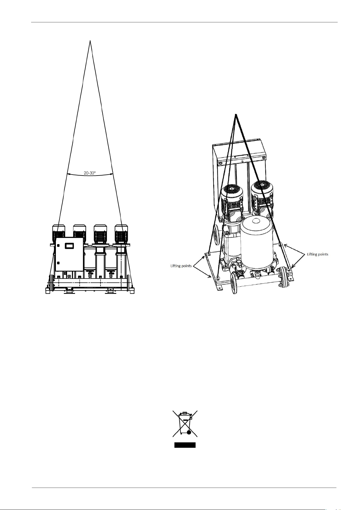
• Lift equipment only at the specifically identified lifting points.
• Lifting devices such as eye bolts, slings and spreaders must be rated, selected and used for the entire load
being lifted
• Select the appropriate lifting points
• Slings should be sized in accordance with the gross weight of the product that is being lifted.
• To minimise tension in legs a sling angle of 20-30° is recommended & appropriate lifting shackles should
be used. See Figure 1.1: Lifting best practice (p. 9).
1) Inspect the package
a) Inspect the package for damage or missing items upon delivery
b) Note any damaged or missing items on the shipping paperwork and contact Dutypoint immediately
c) File a claim with the shipping company if anything is out of order
d) If the product has been picked up at a distributor, file a claim with the distributor
2) Inspect the unit
a) Remove packing materials from the product
b) Dispose of all packing materials in accordance with local regulations
c) Inspect the product to determine if any parts have been damaged or are missing
d) If applicable, unfasten the product by removing any screw, bolts or straps. For your personal safety, be
careful when you handle nails and straps.
e) Contact Dutypoint if you have any issues.
3) Attach appropriate lifting equipment
1. Important Safety Information
9
Figure 1.1: Lifting best practice
1.15 Storage
The product must be stored in a covered and dry location free from heat, dirt and vibrations.
NOTE: Protect the product against humidity, heat sources and mechanical damage
NOTE: Do not place heavy weights on the packed product
1.16 Disposal
At the end of its working life, this product should not be disposed of with standard household waste, but rather
dropped off at a collection point for the disposal of Waste Electrical and Electronic Equipment (WEEE) for recycling.
Figure 1.2: Waste Symbol
This is confirmed by the Waste Symbol found on the product, user manual or packaging.

1. Important Safety Information
10
Defending on their characteristics the materials may be recycled. Through recycling and other forms of processing
Waste Electrical and Electronic Equipment, you can make a significant contribution towards helping to protect the
environment.
Please contact your local authorities for information on the collection point nearest you.
1.17 Potable Water Safety
According to HSE guidance, all water systems should be cleaned, flushed and disinfected as specified in BS EN 806
and BS 8558.
A risk assessment should be performed before commissioning to identify and take into account the potential for
stagnation as this may lead to microbial growth where buildings are not to be fully occupied immediately.
WARNING
The temperature of stored water must be kept below 23° to prevent bacteria growth.
• Storage cisterns should be regularly checked for signs of stagnation or microbial growth
• See HSE guidance for more details: www.hse.gov.uk/legionnaires
This manual suits for next models
4
Table of contents
Other Dutypoint Extender manuals

Popular Extender manuals by other brands


foxunhd
foxunhd SX-AEX01 operating instructions

TERK Technologies
TERK Technologies LFIRX2 owner's manual

Devolo
Devolo Audio Extender supplementary guide

Edimax
Edimax EW-7438RPn V2 instructions

Shinybow USA
Shinybow USA SB-6335T5 instruction manual

SECO-LARM
SECO-LARM ENFORCER EVT-PB1-V1TGQ installation manual