E-flight Blade CX3 MD 520N RTF User manual

Specifications
Length.......................16.4in(415mm)
Height .......................7.2 in (180mm)
Main Rotor Diameter .............13.6 in (345mm)
Weight RTF w/Battery ............8.0 oz (227 g)
Main Motor . . . . . . . . . . . . . . . . . . . . 180 (2 installed)
Battery .......................2S 7.4V 800mAh Li-Po (included)
Transmitter ....................2.4GHz DSM2 5-channel (included)
On-Board Electronics .............3-in-1/mixer/ESC/heading lock gyro (installed)
Servos . . . . . . . . . . . . . . . . . . . . . . . S60 Super Sub-Micro (2 installed)
Receiver ......................Spektrum™6100e (installed)
© 2008 Horizon Hobby, Inc.
4105 Fieldstone Road
Champaign, Illinois 61822
(877) 504-0233
Horizon Hobby UK
Units 1-4 Ployters Rd
Staple Tye
Harlow, Essex
CM18 7NS
United Kingdom
Horizon Hobby Deutschland GmbH
Hamburger Strasse 10
25335 Elmshorn
Germany
Patents pending
DSM and DSM2 are trademarks or registered trademarks of Horizon Hobby, Inc. The Spektrum trademark is
used with permission of Bachmann Industries, Inc. Spektrum radios and accessories are exclusively available from
Horizon Hobby, Inc.
MD 520N®is a registered trademark or trademark of MD Helicopters Inc. and is used under license to
Horizon Hobby, Inc.
SEAHAWK and the Seahawk helicopter design are trademarks of Sikorsky Aircraft Corporation. They are licensed
throughout the world to Horizon Hobby, Inc.
Bell and Jet Ranger are either registered trademarks or trademarks of Textron Innovations Inc. in the USA and/or
other countries, used under license.
www.E-fliteRC.com
Revised 11/08 14475.1

3
4
Table of Contents
Specifications............................................................................................................................................. 2
Introduction................................................................................................................................................ 4
Warning ..................................................................................................................................................... 4
Note on Lithium Polymer Batteries ............................................................................................................... 4
FCC Statement .......................................................................................................................................... 4
Instructions for Disposal of WEEE by Users in the European Union.................................................................. 4
Additional Safety Precautions and Warnings.................................................................................................. 5
Blade CX3 MD 520N RTF Contents .............................................................................................................. 5
Additional Required Equipment..................................................................................................................... 6
Preparing for the First Flight Checklist.......................................................................................................... 6
Flying Checklist .......................................................................................................................................... 6
Battery Warnings and Guidelines.................................................................................................................. 7
Battery Charging ........................................................................................................................................ 9
Charge Errors and Indications.................................................................................................................... 12
Installing the Transmitter Batteries ............................................................................................................. 12
Installing the Flight Battery ........................................................................................................................ 13
Center of Gravity ...................................................................................................................................... 14
Transmitter Control Identification................................................................................................................ 15
Control Test ............................................................................................................................................. 16
3-in-1 Control Unit Description, Arming and Motor Control Test..................................................................... 22
Installing the Optional Training Gear............................................................................................................ 25
Understanding the Controls ....................................................................................................................... 28
Choosing a Flying Area.............................................................................................................................. 32
Flying the Blade CX3 MD 520N.................................................................................................................. 32
Main Motor Proportional Mix Trimmer Pot Description and Adjustment .......................................................... 34
Gyro Gain Trimmer Pot Description and Adjustment..................................................................................... 36
Upper Main Rotor Blade Tracking Adjustment.............................................................................................. 37
Channel 5 Knob Description and Function ................................................................................................... 39
Transmitter and Receiver Binding and Fail-Safe ........................................................................................... 40
Main Motor Care and Installing the Optional Main Motor Heat Sink ................................................................ 42
2008 Official AMA National Model Aircraft Safety Code................................................................................ 43
Replacement Parts List ............................................................................................................................. 45
Optional Parts List .................................................................................................................................... 45
Replacement and Optional Parts .............................................................................................................. 46
Exploded View Parts Listing....................................................................................................................... 47
Exploded View.......................................................................................................................................... 48
Warranty Period........................................................................................................................................ 49
Limited Warranty ...................................................................................................................................... 49
Damage Limits ......................................................................................................................................... 49
Safety Precautions.................................................................................................................................... 49
Questions, Assistance, and Repairs............................................................................................................ 49
Inspection or Repairs ................................................................................................................................ 50
Warranty Inspection and Repairs................................................................................................................ 50
Non-Warranty Repairs ............................................................................................................................... 50
Product Registration ................................................................................................................................. 50
United States ........................................................................................................................................... 51
United Kingdom........................................................................................................................................ 51
Germany.................................................................................................................................................. 51
Declaration of Conformity.......................................................................................................................... 52
Introduction
The Blade®CX3 MD 520N®takes the beginner-friendly flight stability of the Blade CX2 and combines it with
Spektrum™2.4GHz DSM2™technology that lets you fly anywhere, anytime without having to worry about
interference. The CX3 combines the stability and Spektrum DSM2 technology of the CX2 with a stunning new scale
body and ups the ante by including a heading lock gyro .
The Blade CX3 MD 520N is truly a Ready-for-Anyone-to-Fly micro class electric helicopter. Its coaxial counter-
rotating blades cancel out the rotational torque that makes hovering a conventional helicopter so difficult, while
providing unsurpassed stability in all other phases of flight. And whether you are a first-time or an experienced
helicopter pilot, you’ll enjoy many of the outstanding features that have the Blade CX3 MD 520N flying in no time.
Some of these features include: factory installed main motors, 3-in-1 control unit with mixer, ESCs and heading lock
gyro, and S60 Super Sub-Micro Servos. With the included 5-channel transmitter, 2-cell 800mAh Li-Po battery pack,
DC charger and AC adapter, you’ll have precise control for hovering, forward flight and more with flight times of up
to 10–15 minutes per charge.
While the Blade CX3 MD 520N is ready-to-fly right from the box, please take the time to read through this manual
completely for tips on battery safety and charging, control checks, flying and more. Please check out our website
at www.e-fliterc.com for helpful tips and more information about our products.
Warning
An RC helicopter is not a toy! If misused, it can cause serious bodily harm and damage to property. Fly only in open
areas, preferably at AMA (Academy of Model Aeronautics) approved flying sites, following all instructions. Keep
loose items that can get entangled in the rotor blades away for the main and tail blades, including loose clothing, or
other objects such as pencils and screwdrivers. Especially keep your hands away from the rotor blades.
Note on Lithium Polymer Batteries
Lithium Polymer batteries are significantly more volatile than alkaline or Ni-Cd/Ni-MH batteries used in RC
applications. All manufacturer’s instructions and warnings must be followed closely. Mishandling of Li-Po
batteries can result in fire. Always follow the manufacturer’s instructions when disposing of Lithium
Polymer batteries.
FCC Statement
This device complies with part 15 of the FCC rules. Operation is subject to the following two conditions: (1) This
device may not cause harmful interference, and (2) this device must accept any interference received, including
interference that may cause undesired operation.
This product contains a radio transmitter with wireless technology which has been tested and found to be compliant
with the applicable regulations governing a radio transmitter in the 2.400 GHz to 2.4835 GHz frequency range.
The associated regulatory agencies of the following countries recognize the noted certifications for this product as
authorized for sale and use:
Instructions for Disposal of WEEE by Users in the European Union
This product must not be disposed of with other waste. Instead, it is the user’s responsibility to dispose
of their waste equipment by handing it over to a designated collection point for the recycling of waste
electrical and electronic equipment. The separate collection and recycling of your waste equipment at
the time of disposal will help to conserve natural resources and ensure that it is recycled in a manner that
protects human health and the environment. For more information about where you can drop off your waste
equipment for recycling, please contact your local city office, your household waste disposal service or
where you purchased the product.
UK DE DK NO SE FI EE
LV LT PL CZ SK HU RO
SI AT IT ES PT IE NL
LU MT CY GR

5
6
Additional Safety Precautions and Warnings
As the user of this product, you are solely responsible for operating it in a manner that does not endanger yourself
and others or result in damage to the product or the property of others.
This model is controlled by a radio signal that is subject to interference from many sources outside your control.
This interference can cause momentary loss of control so it is advisable to always keep a safe distance in all
directions around your model, as this margin will help to avoid collisions or injury.
• Neveroperateyourmodelwithlowtransmitterbatteries.
• Alwaysoperateyourmodelinanopenareaawayfromcars,trafc,orpeople.
• Avoidoperatingyourmodelinthestreetwhereinjuryordamagecanoccur.
• Neveroperatethemodeloutintothestreetorpopulatedareasforanyreason.
• Carefullyfollowthedirectionsandwarningsforthisandanyoptionalsupportequipment(chargers,rechargeable
battery packs, etc.) that you use.
• Keepallchemicals,smallpartsandanythingelectricaloutofthereachofchildren.
• Moisturecausesdamagetoelectronics.Avoidwaterexposuretoallequipmentnotspecicallydesignedand
protected for this purpose.
• Neverlickorplaceanyportionofyourmodelinyourmouthasitcouldcauseseriousinjuryorevendeath.
Blade CX3 MD 520N RTF Contents
Item Description
Not Available Separately Blade CX3 MD 520N RTF Airframe
EFLH1055 LP5DSM 5-Channel Transmitter, DSM 2.4GHz
EFLB0990 7.4V 800mAh 2-Cell Li-Po, JST/Balance
EFLC3110 2-3 Cell Li-Po Balancing Charger, 0.65A
EFLC4000 AC to 12VDC, 1.5-Amp Power Supply
EFLH1209 Mounting Accessories & Screwdriver
EFLH1022 Bind Plug
FUG4 (Optional) 4 AA batteries
EFLH2009 (Optional) MD520N LED Navigation Light Upgrade Set
Additional Required Equipment
No additional equipment is required to complete your Blade CX3 MD 520N.
Preparing for the First Flight Checklist
Please note this checklist is not intended to be a replacement for the content included in this instruction manual.
Although it can be used as a quick start guide, we strongly suggest reading through this manual completely before
proceeding.
qRemove and inspect contents
qCharge the flight battery
qInstall the 4 included AA batteries in the transmitter
qInstall the flight battery in the helicopter (once it has been fully charged)
qCheck the Center of Gravity of the helicopter
qTest the controls
qInstall the optional Training Gear Set (EFLH1205; strongly recommended if this is your first helicopter model)
qFamiliarize yourself with the controls
qFind a suitable area for flying
Flying Checklist
Please note this checklist is not intended to be a replacement for the content included in this instruction manual.
Although it can be used as a quick start guide, we strongly suggest reading through this manual completely before
proceeding.
qAlways turn the transmitter on first
qPlug the flight battery into the 3-in-1 control unit
qAllow the 3-in-1 control unit to arm properly
qFly the model
qLand the model
qUnplug the flight battery from the 3-in-1 control unit
qAlways turn the transmitter off last

7
8
Battery Warnings and Guidelines
While the 7.4V 800mAh 2-cell Lithium Polymer Battery Pack (EFLB0990) included with your
Blade CX3 MD 520N features Charge Protection Circuitry and Balance Charging via the included
2- to 3-Cell Lithium Polymer Balancing Charger (EFLC3110) to help ensure a safe charge every
time, you MUST read the following safety instructions and warnings before handling, charging or
using the Li-Po battery pack.
Note: Lithium Polymer batteries are significantly more volatile than the alkaline, Ni-Cd or
Ni-MH batteries used in RC applications. All instructions and warnings must be followed exactly.
Mishandling of Li-Po batteries can result in fire.
By handling, charging or using the included Li-Po battery you assume all risks associated with lithium
batteries. If you do not agree with these conditions, return your complete Blade CX3 MD 520N model in
new, unused condition to the place of purchase immediately.
• Youmustchargetheincluded7.4V800mAh2-cellLi-Pobatterypackinasafeareaawayfromammable
materials.
• Donotchargethebatterywheninstalledinthehelicopter.
• Neverchargethebatteryunattended.Whenchargingthebatteryyoushouldalwaysremaininconstant
observation to monitor the charging process and react to potential problems that may occur.
• Afteright,thebatterymustbecooledtoambienttemperaturebeforecharging.
• You MUST use the included 2-3 Cell 7.4-11.1V Li-Po Balancing Charger ONLY. Failure to do so may
result in a fire causing personal injury and/or property damage. DO NOT use a Ni-Cd or Ni-MH charger.
•If at any time during the charge or discharge process the battery begins to balloon or swell,
discontinue charging or discharging immediately. Quickly and safely disconnect the battery, then
place it in a safe, open area away from flammable materials to observe it for at least 15 minutes.
Continuing to charge or discharge a battery that has begun to balloon or swell can result in a fire. A
battery that has ballooned or swollen even a small amount must be removed from service completely.
• Intheeventofacrash,youmustquicklyandsafelydisconnectandremovethebatteryfromthemodel,then
place it in a safe, open area away from flammable materials to observe it for at least 15 minutes.
• Storethebatteryatroomtemperatureandapproximately½charge(3.8Vpercell;7.6Vfora2-cellbatterypack)
for best results.
• Whentransportingortemporarilystoringthebattery,thetemperaturerangeshouldbefrom40–120degrees
Fahrenheit. Do not store the battery or model in a car or direct sunlight whenever possible. If stored in a hot car,
the battery can be damaged or even cause a fire.
• Donotover-dischargethebattery.Dischargingthebatterytoolowcancausedamagetothepack
resulting in reduced performance and duration.
Li-Po cells should not be discharged to below 3V each under load. In the case of the 2-Cell
Li-Po packs used for the Blade CX3 MD 520N, you will not want to allow the battery to fall
below 6V during flight.
The Blade CX3 MD 520N 3-in-1 control unit does not feature a voltage cutoff of any type, so we
suggest that you be extremely aware of the power level of the Li-Po battery pack during flight. If at
any time the helicopter begins to require more throttle than typical to maintain hover or flight, or
has lost significant power, you must land the helicopter and power the motors down IMMEDIATELY to
prevent over-discharge of the Li-Po battery pack. If you continue to run the motors after noticing a
loss in power, it is possible to discharge the Li-Po battery pack too far, causing permanent damage to
the pack.
Over-discharge of the Li-Po battery pack can result in shortened flight times, loss of power output or
failure of the pack entirely.
If you have any further questions or concerns regarding the handling, charging and/or use of the included Li-Po
battery pack, please contact the Horizon Support Team at 877-504-0233.

9
10
Battery Charging
It is important that you only charge the included 7.4V 800mAh 2-cell Li-Po Battery Pack (EFLB0990)
with the included 2-3 Cell 7.4-11.1V Li-Po Balancing Charger (EFLC3110). Your battery pack is
equipped with special Charge Protection Circuitry and a Balance Charge Lead with connector that is
only compatible with this charger. Attempting to charge the pack using another Li-Po charger or a
charger that is not compatible with Li-Po batteries could result in serious damage. Please familiarize
yourself thoroughly with the warnings and guidelines (pages 7–8) before continuing.
The included 2-3 Cell 7.4-11.1V Li-Po Balancing Charger will charge a near fully discharged (not over-discharged)
7.4V 800mAh 2-cell Li-Po Battery Pack in approximately 1.2–1.5 hours. In some cases the charge time may be
shorter depending on the actual amount of capacity left in the pack after a flight. NEVER charge the battery
unattended.
Note: The Li-Po battery pack included with your Blade CX3 MD 520N will arrive partially charged. For this reason
the initial charge may only take approximately 30–50 minutes.
The charger requires up to 1.5-amps of 11.5- to 15-volt DC input power that can be supplied by the included AC to
12V DC, 1.5-Amp Power Supply (EFLC4000) for convenient charging anywhere an AC outlet is available.
NEVER attempt to power the charger from an AC outlet without the use of a proper AC to DC adapter/
power supply.
Note: When using the AC to DC adapter/power supply, the charger is protected to prevent damage if the alligator
clips touch. However, please take care to ensure that the alligator clips do not cause shorting of the battery,
adapter/power supply, etc. by keeping them clear.
Input power for the charger can also be supplied from a small 12V gel cell or car battery.
The charger is equipped with two LED indicators marked RED and GREEN on the label. These LEDs indicate the
following (also found on the label of the charger):
• Red Flashing LED Only: Input power with no battery connected
• Red and Green Solid LED: Battery connected and charging
• Red Solid LED Only: Charge complete
• Red and Green Flashing LED: Charge error
11
12
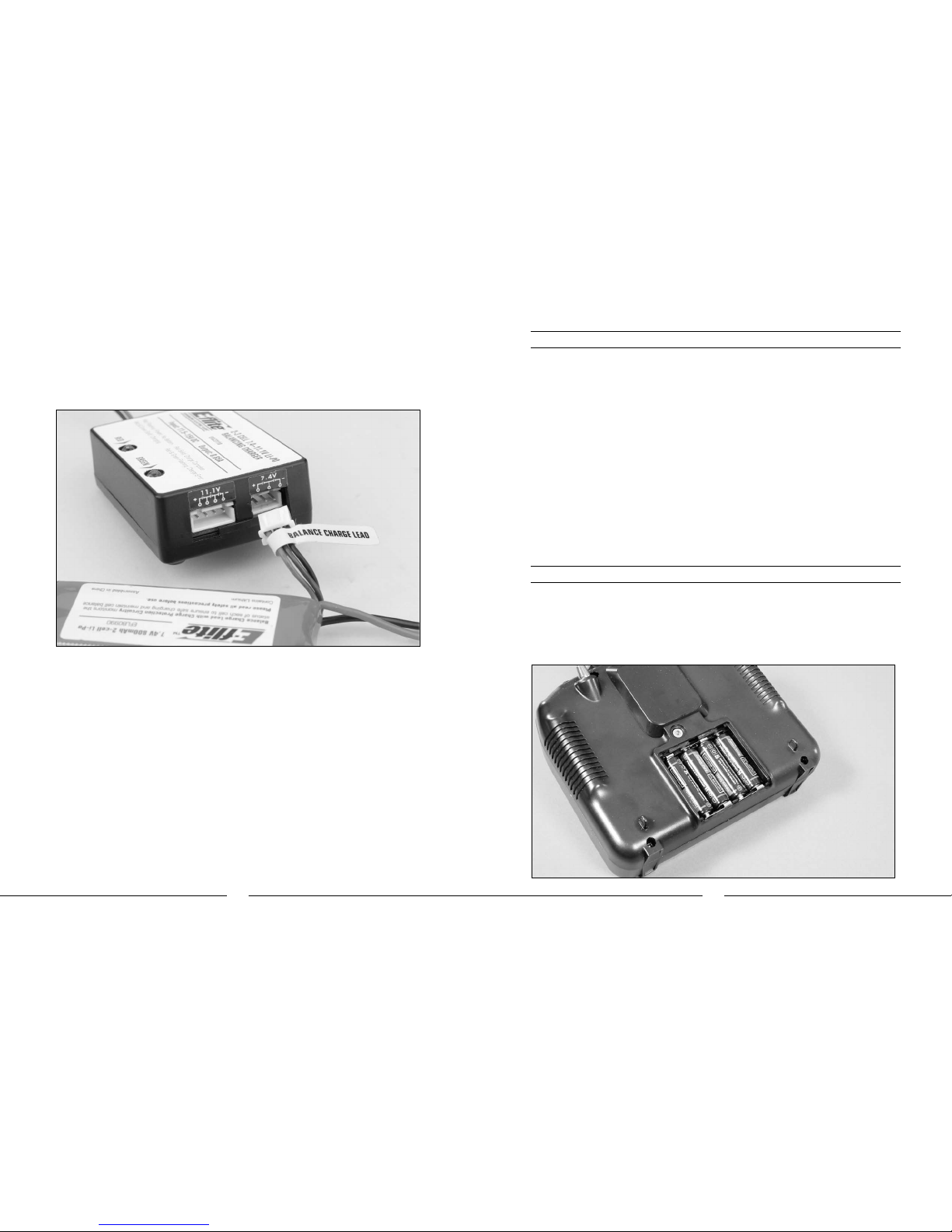
Once you have connected the charger to a power source (use care to ensure proper polarity when connecting
the charger to the power source), its red LED will flash to indicate the charger has power and is ready to begin
charging. Connect the Li-Po battery pack to the charger using the specially marked Balance Charge Lead exiting
the battery pack and the connector labeled with 7.4V on the charger. The connector is keyed to prevent reverse
polarity connection.
Note: Do not force the connector on the Balance Charge Lead into the connector labeled 11.1V on the charger.
Doing so could result in damage to the battery pack and charger, and could result in a fire.
When the battery is properly connected and charging normally, the red and green LED indicators will glow solid.
Once the battery has been fully charged, the green LED will go out, leaving just the red LED glowing solid. The
battery can now be removed from the charger and installed into the Blade CX3 MD 520N for flight.
Charge Errors and Indications
In the event that both the red and green LEDs flash, a charge error has occurred. Some examples of
charge errors and their indications include:
• AlternatingashingoftheredandgreenLEDswillindicatethatthechargeprocesshasbeeninterrupted.Ifinput
power to the charger has been interrupted due to disconnection from the power source or a drop in voltage/
current output from the power source, unplug the battery from the charger. Next, check to make sure that the
input power plug from the AC to 12V DC adapter/power supply is connected or that the alligator clips are firmly
and properly attached to the power source. Also be sure that the power source is providing the proper amount of
voltage and current required to the charger.
After confirming the connections and that the power source is delivering the necessary voltage and current, re-
start the charge process by connecting the battery pack. Continue to monitor the charge process to ensure that
no further charge errors occur.
• SimultaneousashingoftheredandgreenLEDswillindicatethatthevoltageoftheLi-Pobatterypackistoolow
to allow the charge process to begin. In this case the battery may have been over-discharged due to flying the
model too long (For more information on preventing over-discharge of the Li-Po battery pack, see the guidelines
section found on page 9), or that a single cell or even all cells in the battery pack may be damaged.
If after several charging attempts you continue to see this charge error indication, you should remove
the battery pack from service and replace it with a new one.
If you have any further questions or concerns regarding charge error indications, please contact the Horizon
Support Team at 877-504-0233.
Installing the Transmitter Batteries
Install the 4 included AA batteries in the transmitter. Check the power level of the batteries and operation of the
transmitter by switching the power switch on (upward). The LCD screen at the top of the transmitter will indicate the
power level of the batteries. If at any time the voltage indicated on the LCD screen falls to 4.0V or less, it will be
necessary to replace the batteries with new ones.
Note: Because the LP5DSM transmitter included with the Blade CX3 MD 520N is equipped with Spektrum 2.4GHz
DSM2 technology, it does not require the same input voltage or current consumption as a typical 72MHz transmitter
for proper operation and optimum performance.

13
14
Installing the Flight Battery
Use the included hook and loop material for mounting the Li-Po battery pack. The “hook” material is already installed
on the battery frame stop. The included “loop” material can be installed on the end of the battery without the wire
leads, depending on how you choose to install the battery and route the wire leads.
The battery can be installed through the opening on the bottom of the MD 520N body. Be sure to install the end of
the battery with the leads first, toward the front at an angle, then slide the battery toward the back until the “loop”
material on the battery securely fastens to the “hook” material on the battery frame stop.
Center of Gravity
Once the battery has been properly installed and secured you will need to check the helicopter’s center of gravity. If
the helicopter is not properly balanced it can be difficult to control and constantly try to move forward or backward
in hover.
To check the center of gravity, lift the helicopter by the stabilizer flybar with the flybar positioned perpendicular to
the tail section of the body. Make sure that the helicopter balances level. If it does not, confirm that the battery has
been properly installed and reposition it forward or aft if necessary.
Skids Must Be Level
Support by Flybar
Step 1
Step 2
Step 3
Step 4

15
16
Transmitter Control Identification
Note: EachtimebeforeyouyyoushouldALWAYSturnthetransmitteronbeforeconnectingtheightbatteryto
the unit. After each flight, be sure that you always disconnect the flight battery from the unit before powering the
transmitter off.
Control Test
Although each Blade CX3 MD 520N model is test flown at the factory, it is a good idea to test the controls prior to
the first flight to ensure none of the servos, linkages or other parts were damaged during shipping and handling.
Before proceeding, ensure your throttle stick and trim are at the lowest possible position.
Turn the transmitter on first then plug the battery into the battery lead of the 3-in-1 unit.
Throttle Trim
Aileron Trim
Elevator Trim
Rudder Trim
Rudder Trim
Elevator Trim
Aileron Trim
Throttle Trim
Rudder/Throttle
Functions
Rudder/Elevator
Functions
Aileron/Elevator
Functions
Aileron/Throttle
Functions
Mode 1
Mode 2
Mode 2 Mode 1

17
18
When the stick is pulled back, the servo on the right should pull the swashplate downward.
Mode 2 Mode 1
Position the helicopter to view it from the FRONT
Move the elevator control stick on the transmitter forward and back to check elevator pitch control. When the stick
is pushed forward, the servo on the right side should push the swashplate upward.
Mode 2 Mode 1

19
20
Move the right-hand control stick on the transmitter left and right to check aileron roll control. When the stick is
pushed to the left, the servo on the left side should push the swashplate upward.
When the stick is pushed to the right, the servo on the left should pull the swashplate downward.
Mode 2 Mode 1
Mode 2 Mode 1
21
22
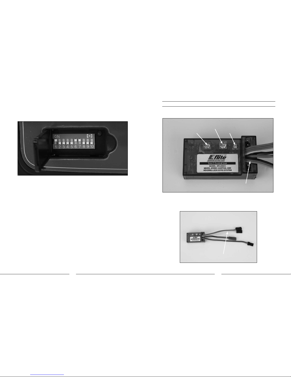
If at any time during the test the controls do not respond properly, double-check the servo reversing switches
located under the door on the bottom left front of the transmitter. Dip switches 1, 6 and 7 should be positioned as
shown to ensure proper servo reversing.
Note: All other dip switches should also be positioned as shown to ensure proper operation. DO NOT
attempt to fly your Blade CX3 with any of the dip switches set in positions that are not shown.
If the controls still do not respond properly after ensuring that the servo reversing dip switch positions are correct,
you may also check the servo connections on the receiver side of the 3-in-1 unit. These should be positioned as
follows (when viewing the helicopter from behind):
AIL Channel – Servo on the right side of the heli
ELE Channel – Servo on the left side of the heli
Once you have confirmed that the servo connection locations are correct, all controls should be functioning
properly. If you do encounter any problems with your Blade CX3 MD 520N responding properly to the transmitter,
do not fly. Contact the Horizon Support Team at 877-504-0233.
3-in-1 Control Unit Description, Arming and Motor Control Test
The unique 3-in-1 Control Unit installed on your Blade CX3 MD 520N is a lightweight combination of a main motor
mixer, main motor electronic speed controls, and a heading lock gyro. The 3-in-1 unit also contains a gyro gain
trimmer pot, main motor proportional mix trimmer pot and status LED.
If you should ever need to access the 3-in-1 unit (usually only required if making adjustments to the gyro gain or
main motor proportional mix trimmer pots, as outlined on pages 34–35), you can do so by going through the front
window of the MD 520N scale body.
Note: It will not be necessary to access the 3-in-1 unit for proper arming and usual operation.
Note: The 3-in-1 unit has an optional remote gyro gain plug.
Gain Trimmer Pot Status LED
Motor Plugs
Main Motor Porportional
Mix Trimmer Pot

23
24
The following checklist contains the steps you must follow to ensure proper arming and operation of the 3-in-1 unit
as well as proper motor control response:
qEach time before you fly you must ALWAYS turn on the transmitter power first before connecting
the flight battery to the 3-in-1 unit. Never connect the flight battery to the 3-in-1 unit before first
powering on the transmitter.
Also, never turn off the transmitter before disconnecting the flight battery from the 3-in-1 unit first.
qBoth the throttle stick and throttle trim MUST be in their lowest possible position in order for the
3-in-1 unit to arm the electronic speed controls for the main motors.
If this is the first test flight, or a test flight following repairs, you will also want to center the rudder, aileron and
elevator trims (see photo found on page 15 for reference).
qAfter confirming that the transmitter has been turned on and has an adequate level of battery power as displayed
by the LCD screen at the top of the transmitter, it is now safe to connect the flight battery to the 3-in-1 unit.
Note: Each time you power the transmitter on, it will enter “Bind Mode” (See pages 40-41 for
more information regarding “Bind Mode”) for a few seconds, as indicated by the red blinking LED
located under the door on the left bottom front of the transmitter. Once this LED becomes solid, the
transmitter is no longer in bind mode. We recommend waiting to connect the flight battery to the
3-in-1 unit after the transmitter has exited bind mode, otherwise the 3-in-1 may not arm properly or
as quickly.
• With battery power applied, the 3-in-1 unit status LED will blink red, and then blink green. It is
extremely important that you do not move or sway the helicopter once the status LED begins to blink
green confirming that the initialization process and calibration of the gyro has begun. It is OK to move
the model when the status LED is blinking red (as in the time it takes to connect the flight battery to the 3-in-1
unit and place the model at rest), as long as the model remains motionless when the status LED begins to blink
green.
• When the status LED becomes solid green, the unit is armed and ready for flight. Use caution as both
main motors will now run with throttle stick or throttle trim input. Do not advance the throttle stick or trim until
you are clear of the rotor blades and ready to fly.
Note: If the status LED does not become solid green, please review the following:
• IfafterblinkingredthestatusLEDbecomessolidred,youhaveapositiveRadioFrequency(RF)linkbetween
the transmitter and receiver of the 3-in-1 unit, but the throttle stick and throttle trim may not be in their lowest
possible positions. Check to be sure that both the throttle stick and throttle trim are in their lowest possible
position and the status LED should blink green then become solid green indicating the unit is armed and ready for
flight. Proceed to the next step of the checklist once the unit is armed.
• IfafterblinkingredthestatusLEDturnsoff,youdonothaveapositiveRFlinkbetweenthetransmitterand
receiver of the 3-in-1 unit. First, check to be sure that the transmitter has been powered on and has an adequate
level of battery power. If the transmitter was indeed powered on, power both the transmitter and 3-in-1 unit down,
then follow the steps to bind the 3-in-1 unit’s receiver to the transmitter (see pages 40–41 for more information).
Once you have confirmed that the transmitter and receiver are properly bound, the 3-in-1 unit should now arm
normally.
If your 3-in-1 unit will not arm after following the guidelines as listed above, contact the Horizon Support Team at
877-504-0233.
qOnce you have placed the helicopter in a safe area to test motor control, free from obstructions, and
are clear of the rotor blades, you can safely begin to power up the model.
qAdvance the throttle stick slowly, just until the main rotor blades begin to spin. Be sure not to advance the
throttle stick too far to keep the helicopter from lifting off the ground. Note the direction that each of the main
rotor blades spins. When viewed from the top, the lower main rotor blade should spin clockwise and the upper
main rotor blade should spin counterclockwise. If either rotor blade is operating in the wrong direction, unplug the
battery, then simply reverse its motor plug polarity on the 3-in-1 unit. Note that the proper polarity is marked on
the label of the 3-in-1 unit.
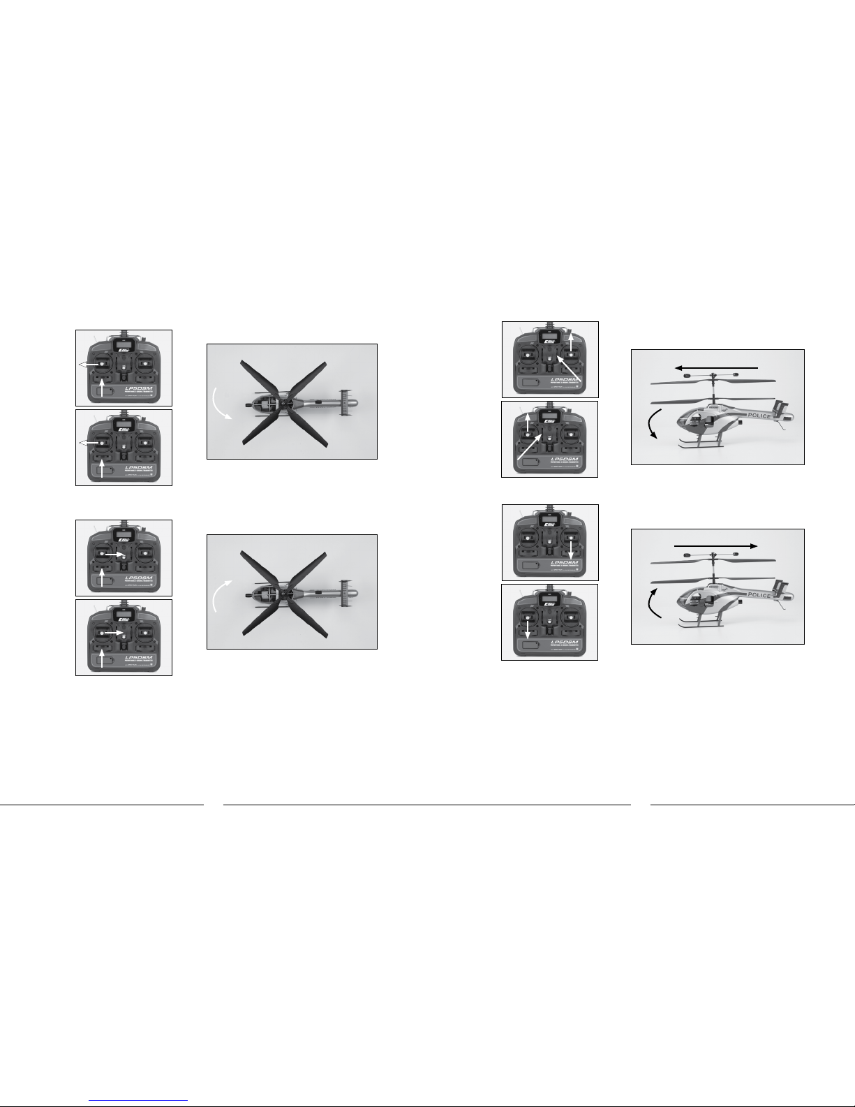
qAfter confirming that the direction of rotation for both rotor blades is correct, it is best to confirm that both rotor
blades respond properly to rudder control inputs. With both main rotor blades spinning at a low level of power,
move the rudder stick all the way to the right. This should cause the speed of the upper main rotor blade to
increase, and the speed of the lower main rotor blade to decrease. Next, move the rudder stick all the way to the
left. This should cause the speed of the lower main rotor blade to increase and the speed of the upper main rotor
blade to decrease. If both rotor blades are not responding properly to rudder input, simply reverse the locations
of their motor plugs on the 3-in-1 unit. Note that the proper motor plug locations are marked on the label of the
3-in-1 unit.
qAfter confirming both main rotor blades respond properly to rudder inputs, your Blade CX3 MD 520N is now
ready for flight. However, please be sure to review the following sections of the manual before proceeding with
the first flight.
25
26
Installing the Optional Training Gear
If the Blade CX3 MD 520N is your first helicopter model, we suggest that you install the optional
Training Gear Set (EFLH1205) before making your first flight. The training gear helps to further increase the stability
of the model while also providing added support and cushioning to prevent tip-overs and damage to the model from
abrupt landings.
Installing the training gear takes only a few minutes following these steps:
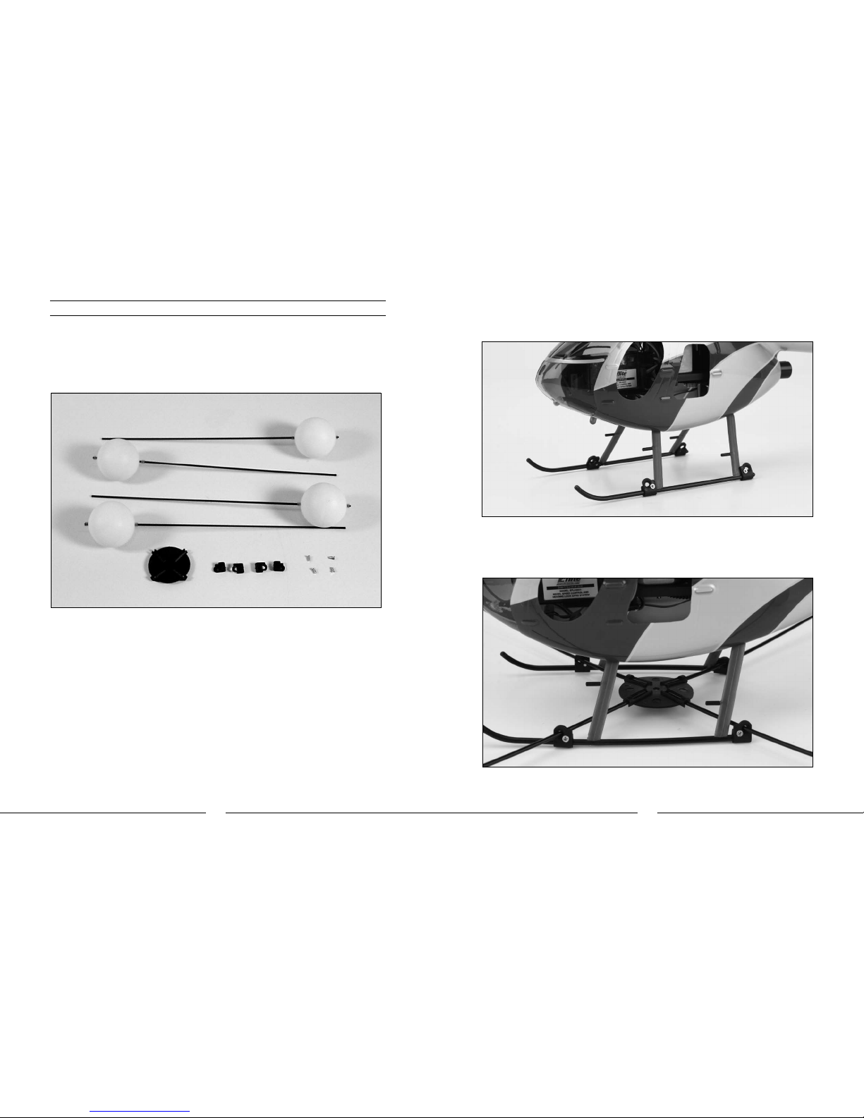
• TheTrainingGearSetincludesfourtraininggearrodswithplasticballsinstalled,fourtraininggearrodtolanding
skid attachments, four screws and one training gear rod mounting base.
• Locatethefourtraininggearrodtolandingskidattachmentsandfourscrews.Notethattherearetwoeachof
two types of attachments. Carefully snap two of the attachments onto the landing skids forward of the landing
skid struts. The side of the attachment with the large hole should face outward, away from the helicopter, and
forward to the front of the helicopter.
• Next,carefullysnaptheremainingtwoattachmentsontothelandingskidsbehindthelandingskidstruts.The
side of the attachment with the large hole should face outward, away from the helicopter, and backward to the
rear of the helicopter.
• Onceyouhaveinstalledallfourattachments,installthefourscrewsmakingsurethattheythreadproperlyinto
the back side of the attachment. It may be helpful to squeeze the attachment with a pair of pliers to make it
easier to thread the screw into the backside of the attachment. Do not tighten the screws all the way at this time,
as the attachments will need to be adjusted for proper alignment once the training gear rods are installed.
• Locatethefourtraininggearrodsandrodmountingbase.Notethattherodmountingbasehasfourchannels
into which the training gear rods will mount. The open side of these channels will face upward toward the bottom
of the helicopter when properly installed.
• Carefullypasseachoftherodsthroughtheattachmentsonthelandingskidsandintothechannelsonthebase.
Take care to not pull the landing skids out of their mounts in the battery supports.
27
28
• Afterensuringthattherodsaresecureinthebase,adjustthepositionsoftheattachmentsonthelandingskids
so that the base is centered under the main shaft of the helicopter. Once confirming the base is centered under
the main shaft, make sure that each of the landing skids is still firmly installed in the mounts of the battery
supports. Note that the landing skids may be pulled slightly inward under pressure of the training gear rods.
• Withtheattachments,rodsandbaseproperlypositioned,youcannowtightentheattachmentscrewsuntilthey
are just snug. Take care when tightening the screws to prevent stripping the backside of the attachments.
• Adjustthepositionofthetubingkeepersandplasticballsonthetraininggearrodssothattheballsare
positioned approximately 1/8” from the end of each rod. Be sure that the tubing keepers are positioned so that
the plastic ball can still spin freely on the rod.
YourBladeCX3MD520Nisnowreadyforightwiththetraininggearinstalled.
Understanding the Controls
If you are not familiar with the controls of your Blade CX3 MD 520N, please take a few minutes to familiarize
yourself with them before attempting your first flight.
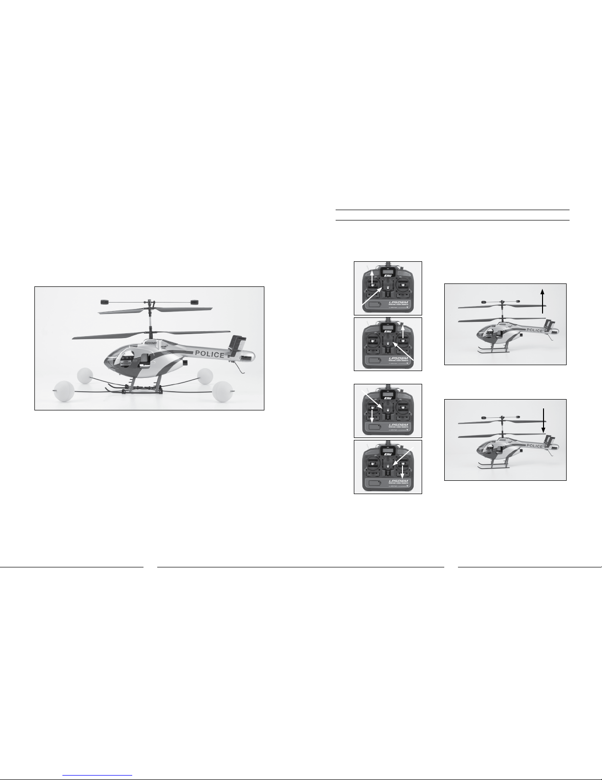
The throttle stick on the transmitter controls climb/descend. When the throttle stick and throttle trim lever are in
their lowest positions, the main rotor blades will not spin. Advancing the stick upward will increase the speed of the
main rotor blades. Increasing the speed of the main rotor blades will cause the model to climb.
Decreasing the speed of the main rotor blades by lowering the throttle stick will cause the model to descend.
After lifting the model off the ground you can balance the throttle by carefully moving the throttle stick up and down
so that the model will hold a stationary hover without climbing or descending.
You can also use the throttle trim to adjust the throttle value for a given stick position. For example,
raising the throttle trim will allow the model to hover at a lower throttle stick position. However, if you
do raise the throttle trim, you MUST remember to lower it (and the throttle stick) to the lowest possible
position IMMEDIATELY in the event of a crash or rotor blade strike.
Failure to lower the throttle trim (and throttle stick) to its lowest possible position immediately in the
event of a crash could result in damage to the main motor ESCs in the 3-in-1 unit, which may require
replacement of the 3-in-1 unit.
Mode 2
Mode 2
Mode 1
Mode 1
Climb
Descend
29
30
Moving the rudder stick to the left will turn (yaw) the nose of the helicopter to the left about the axis of the main
shaft. This is accomplished by increasing the speed of the lower main rotor blade while decreasing the speed of the
upper main rotor blade.
Moving the stick to the right will turn (yaw) the nose of the helicopter to the to the right about the axis of the main
shaft. This is accomplished by increasing the speed of the upper main rotor blade while decreasing the speed of
the lower main rotor blade.
The rudder trim can be used to help keep the nose of the helicopter from rotating to the left or right when in hover
with no rudder stick input. For example, if the nose of the helicopter drifts to the right when in hover, add left rudder
trim until the nose stays as close to straight as possible. Also note that further adjustments to the rudder trim can
be made using the Main Motor Proportional Mix Trimmer Pot as outlined on page 34–35.
Mode 2
Mode 2
Mode 1
Mode 1
NoseYawLeft
NoseYawRight
The elevator stick controls both elevator fore and aft pitch. Pushing the stick forward will pitch the nose of the
helicopter downward, causing the helicopter to fly forward.
Pulling the stick backward will pitch the tail of the helicopter downward, causing the helicopter to fly backward.
The elevator trim can be used to help keep the helicopter from drifting forward or backward when in hover with no
elevator stick input. For example, if the helicopter drifts forward when in hover, pull the elevator trim downward until
the helicopter hovers as level as possible with no forward drifting.
Helicopter Moves Forward
Helicopter Moves Backward
Mode 2
Mode 2
Mode 1
Mode 1

31
32
The aileron stick controls roll. Moving the stick left will roll the helicopter to the left, causing the helicopter to fly to
the left.
Moving the stick to the right will roll the helicopter to the right, causing the helicopter to fly to the right.
The aileron trim can be used to help keep the helicopter from drifting left or right when in hover with no aileron stick
input. For example, if the helicopter drifts to the right when in hover, add left aileron trim until the helicopter hovers
as level as possible with no drifting to the right.
Once you have become familiar with the controls of the helicopter, you are almost ready to fly.
Mode 2
Mode 2
Mode 1
Mode 1
Helicopter Moves Left
Helicopter Moves Right
Choosing a Flying Area
When you are ready for your first flight, you will want to select a large, open area that is free of people and
obstructions. We strongly recommend an indoor area with at least 20-feet by 20-feet of floor space and
no less than 8-foot ceilings.
If you have to make your first flight outdoors, you MUST pick a time when wind conditions are
COMPLETELY CALM. Due to the relatively small size and low weight of the Blade CX3 MD 520N, even the
slightest amount of wind can cause you to lose control, or the rotor blades to strike in the air, resulting in a crash.
Flying the Blade CX3 MD 520N
Having followed the proper 3-in-1 control unit arming procedure, confirmed proper control of the servos and motors,
and found a suitable flying area, your Blade CX3 MD 520N is ready for flight.
In addition to reviewing the flight maneuvers outlined below, we recommend that you watch the Instructional
Video online at www.E-fliteRC.com to see many of these maneuvers and adjustments performed by the
Blade CX3 MD 520N and pilot.
• Slowlyraisethethrottlestick,increasingthespeedofthemainrotorbladesuntilthemodelbeginstoliftoff.
Do not raise the throttle stick too quickly as the model could climb too fast causing you to lose control or make
contact with objects above.
• Liftthemodeloffthegroundjustafewinchesandconcentrateonbalancingthethrottlestickpositionsothatthe
model holds a steady hover altitude. In some cases it may be best to make a few short “hops” to an altitude of
just a few inches until you become familiar with the control inputs and trim settings required to maintain a steady
hover and altitude.
As you will find, the Blade CX3 MD 520N requires minor throttle adjustments to maintain its altitude in hover.
Remember to keep these throttle adjustments as minimal as possible as large adjustments could result in a loss
of control and/or a possible crash.
• Whileattemptingtoestablishalow-levelhover,youcanalsochecktoseeifanytrimadjustmentsarerequiredto
help keep the Blade CX3 from constantly drifting in various directions. If you find the helicopter constantly drifts
without any directional control input, it will be best to land the model before making any adjustments to the trim
levers.
If the nose of the helicopter does not stay pointed in one direction, but is drifting to the left or right,
you will need to adjust the rudder trim.YoucanalsoadjusttheMainMotorProportionalMixifyouexperience
any difficulties in trimming nose drift with the rudder trim lever only. Please see pages 34–35 for more
information regarding Main Motor Proportional Mix Trimmer Pot adjustment.
If the helicopter is drifting forward or backward, you will need to adjust the elevator trim.
If the helicopter is drifting to the left or right, you will need to adjust the aileron trim.
Continue to make trim adjustments until the helicopter can hover at a low altitude with very little drifting and
directional control input. If the Blade CX3 MD 520N is your first helicopter model, it may be best to have the help
of an experienced helicopter pilot to trim the model for you before making your first flight.
• OnceyouhavetheBladeCX3MD520Nproperlytrimmedandmaintainingastablelow-levelhover,practice
using the rudder, elevator and aileron controls to get a feel for how the helicopter responds to control inputs.
Remember to keep the control inputs as minimal as possible to prevent over-controlling the helicopter, especially
when in hover.
• AfterbecomingcomfortablewithhoveringtheBladeCX3MD520Natlow-levelsofaltitudejustafewinchesoff
the ground, you can transition to hovering and flying the helicopter at higher altitudes of approximately three to
four feet. At these higher altitudes you will be able to get a feel for the flight characteristics of the Blade CX3
when it is flying out of “ground effect.”
• Ifatanytimeduringightyoufeellikethehelicopterisdriftingoutofcontrol,simplyreleaseallofthecontrols
exceptforthrottle.Youwillneedtousethethrottletomaintainaltitude,butduetotheinherentstabilityofthe
coaxial counter-rotating blades, the Blade CX3 will simply return to a stable hover on its own if space allows.
• Don’tbeafraidtosetthehelicopterdownonthegroundquicklybyloweringthethrottlewhenapproachingwalls

33
34
or other obstacles to help prevent main rotor blade strikes. Also, the optional Training Gear Set (EFLH1205) will
help to further prevent damage to the helicopter in the event that you must make an abrupt landing to avoid walls
or other obstacles.
• INTHEUNFORTUNATEEVENTOFACRASHORROTORBLADESTRIKE,NOMATTER
HOW MINOR OR MAJOR, YOU MUST LOWER BOTH THE THROTTLE STICK AND
THROTTLE TRIM TO THEIR LOWEST POSSIBLE POSITION AS QUICKLY AS POSSIBLE
TO PREVENT DAMAGE TO THE ESCS OF THE 3-IN-1 UNIT.
Failure to lower both the throttle stick and throttle trim to their lowest possible positions in the event
of a crash could result in damage to the main motor ESCs in the 3-in-1 unit, which may require
replacement of the 3-in-1 unit.
Note: Crash damage is not covered under warranty.
• ItisextremelyimportantwhenhoveringandyingtheBladeCX3MD520Ntobeawareofthepower
level of the Li-Po battery pack. If at any time the helicopter begins to require more throttle than
typical to maintain hover or flight, or has lost the ability to maintain hover or flight due to significant
loss of power, you must land the helicopter and power the motors down IMMEDIATELY to prevent
over-discharge of the Li-Po battery pack.
If you continue to run the motors after noticing a loss in power it is possible to discharge the Li-Po
battery pack too far, causing permanent damage to the pack. Over-discharge of the Li-Po battery
pack can result in shortened flight times, loss of power output or failure of the pack entirely.
• OnceyouhavegainedexperienceandcondenceinhoveringtheBladeCX3MD520N,youcanattemptmore
advanced maneuvers including:
Forward Flight
Backward Flight
Pirouettes
Skidding Takeoffs
Skidding Landings
Spot Landings
Main Motor Proportional Mix Trimmer Pot Description and Adjustment
The Main Motor Proportional Mix Trimmer Pot can be found on the left side of the 3-in-1 control unit. This
“proportional” trimmer pot adjusts the amount of mixing between the main motors allowing you to “fine-tune” the
rudder trim (sub-trim) to help prevent the nose from drifting to the left or right when in hover.
• Inastablehover,withtheruddertrimcenteredandnoruddercontrolinput,notethedirectionthenoseof
the helicopter is drifting. If the nose of the helicopter is drifting to the left, you will want to increase power to
the right-hand motor (spinning the upper main rotor blade). This is accomplished by turning the “proportional”
trimmer pot clockwise (+).
Main Motor
Proportional Mix
Trimmer Pot

35
36
• Ifthenoseofthehelicopterisdriftingtotherightinhover,youwillwanttoincreasethepowertotheleft-hand
motor (spinning the lower main rotor blade). This is accomplished by turning the “proportional” trimmer pot
counterclockwise (-).
Note: You must always power down the 3-in-1 unit before making adjustments to the proportional
mix trimmer pot. Any changes made to the trimmer pot will not take effect until the 3-in-1 unit is re-
initialized and re-armed.
Also, you should always center the rudder trim lever on the transmitter after making adjustments to the proportional
mix trimmer pot on the 3-in-1 unit.
Note: Be sure to use the proper size and type of screwdriver to carefully make adjustments to the trimmer pot.
Use of the improper size and type of screwdriver or too much force can damage the trimmer pot. Also be sure
to take your time when making adjustments to the proportional trimmer pot as it may only require very slight
adjustment to achieve the desired level of performance (less than 1/8 of a turn).
As the battery output voltage decreases throughout the flight, it may be necessary to make small adjustments to
the rudder trim or rudder control input in order to keep the nose of the helicopter straight. These small adjustments
can be made using the rudder trim lever or rudder control stick and do not require additional adjustments of the
proportional trimmer pot.
Gyro Gain Trimmer Pot Description and Adjustment
The “gain” trimmer pot adjusts the gain setting value of the piezo gyro used to aid in keeping the tail of the
helicopter straight/on heading during flight.
• Thegainvalueissettoohighifthetailofthehelicoptertwitches/bouncesquicklyfromsidetosidewhenin
hover. If this is case for your model, reduce the gyro gain in small increments until the tail of the helicopter no
longer twitches/bounces from side to side in hover.
Turn the gyro gain trimmer pot counterclockwise (-) to decrease gyro gain.
• Thegainvalueissettoolowwhenthetailofthehelicopterfeels“loose”duringight,requiringconstantleftand
right rudder inputs to maintain heading when in hover. If this is the case for your model, increase the gyro gain in
small increments until few, if any, left and right rudder inputs are required to maintain heading.
Turn the gyro gain trimmer pot clockwise (+) to increase gyro gain.
Note: When adjusting the gyro gain trimmer pot, the changes will take effect without the need to power
down and re-arm the 3-in-1 unit. Please exercise extreme caution when adjusting the gyro gain trimmer
pot with the model armed to prevent personal injury or damage to the model.
Gain Trimmer Pot

37
38
Upper Main Rotor Blade Tracking Adjustment
Caution: Be sure to maintain a safe distance from the helicopter (approximately 10–15 feet) when
tracking the Upper Main Rotor Blade.
YourBladeCX3MD520NisequippedwithanadjustablelinkagebetweentheStabilizerFlybarandUpperMain
Rotor Blade. This linkage allows you to adjust the tracking of the upper main rotor blade for smoother and more
stable flight performance.
• Youcanchecktheuppermainrotorbladetrackingeitheronthegroundorintheairateyelevel.Itmightbea
good idea to have an assistant on hand to help sight the blade tracking.
• Oncethemainrotorbladeshavebeenbroughtuptospeed,notewhetherthetipsoftheuppermainrotorblade
are tracking in the same plane or not.
• Ifthetipsarenottrackinginthesameplane,powerthehelicopterdowntomakeadjustmentstotheadjustable
linkage.Youcanstartbyturningtheendsofthelinkageinone-halftoone-fullturnatatime.Powerthehelicopter
up again and re-check the blade tracking.
If the tracking has improved, continue to turn the ends of the linkage in one-half to one-full turn at a time until the
tips are tracking in the same plane.
If the tracking has become worse after first turning the ends of the adjustable linkage in, turn the ends of the
linkage back out one-half to one-full turn at a time. If the tracking then gets better, continue to turn the ends of
the linkage out one-half to one-full turn at a time until the tips are tracking in the same plane.
Typically, not much adjustment should be necessary to properly track the tips of the upper main rotor blade.
However, due to the small size of the linkage ends and threaded rods it may not always be possible to achieve
absolutely perfect blade tracking. Don’t worry as the helicopter will still perform well as long as the blade tracking is
adjusted as closely as possible.
Note: It will not be necessary to adjust the Lower Main Rotor Blade tracking as fixed links are used between the
rotor blade and swashplate.
Tips Out Of Track—
Adjustment Necessary
Tips In Track—
No Adjustment Necessary

39
40
Channel 5 Knob Description and Function
The transmitter included with your Blade CX3 MD 520N is equipped with an optional-use “Channel 5” knob (labeled
as “CH 5”) on the top right panel.
This knob allows you to control function of the transmitter’s 5th channel. This channel remains un-used for flying
the Blade CX3 MD 520N, however, it is available for use in controlling a variety of potential optional features
including actuation of an additional servo or certain electronic components. It allows full proportional control of the
5th channel from approximately 0–100% travel.
Although no servo reversing is available for this channel, the knob can be operated in either direction for
control.Youcanuseeitherthemostclockwise(+)ormostcounterclockwise(-)positionfor0or100%travel,
and you will achieve approximately 50% travel with the knob in the middle position, pointing directly to the rear of
the transmitter.
0% (or 100%) Travel
50% Travel
100% (or 0%) Travel
Transmitter and Receiver Binding and Fail-Safe
Binding is the process of programming the receiver to recognize the GUID (Globally Unique Identifier) code of a
single specific transmitter. If you ever find that it is necessary to replace your transmitter or the AR6100e in your
model, it will be necessary for you to “Bind” the new transmitter AR6100e receiver to your existing transmitter or
receiver for proper operation.
During the binding process, the smart fail-safe (SmartSafe™) positions of your system are also set. With SmartSafe,
in case of loss of signal, the throttle will go to the preset position that was stored during the binding process and
all other channels will hold their last position. And if the receiver (AR6100e) is powered on before the transmitter, all
channels but throttle will go to the fail-safe positions that were stored during the binding process, while the throttle
channel will not generate a pulse in order to prevent the ESC(s) from arming.
Note: Because the SmartSafe positions are set during the binding process, it is important to set all channels to the
preferred fail-safe positions before proceeding. In the case of the Blade CX3 MD 520N, we strongly recommend
setting the throttle stick and throttle trim to their lowest positions, and the rudder, aileron and elevator channels to
their neutral positions. Channel 5 should be set to your preferred position if you have chosen to utilize it.
The following steps outline the binding process:
• Eachtimethetransmitteristurnedon,itenters“BindMode”forafewseconds.Youcantellthatthetransmitter
is in bind mode when you see the red LED located under the door on the bottom left front of the transmitter blink
rapidly. Once the LED becomes solid, the transmitter is no longer in bind mode and will transmit normally.
Table of contents
Other E-flight Toy manuals


Popular Toy manuals by other brands


Learning Resources
Learning Resources Gears! Gears! Gears! Lights & Action Activity guide

Pinolino Kinderträume
Pinolino Kinderträume Prinzessin Lea Assembly plan

Acctron
Acctron Vertex-Link Mini user manual

Fisher-Price
Fisher-Price Thomas & Friends Take-n-Play Portable Railway... instructions

LEGO
LEGO Friends 41028 manual

LEGO
LEGO Friends 41037 Building instructions

Ofna Racing
Ofna Racing Ultra LX ONE instruction manual

21st Century Toys
21st Century Toys The Ultimate Soldier M1A2 Abrams Tank owner's manual

MTHTrains
MTHTrains RAILKING Rotary Snow Plow manual

marklin
marklin 37138 user manual

Mega Construx
Mega Construx DPG73 manual

RR-Concepts
RR-Concepts StationMaster-6 manual