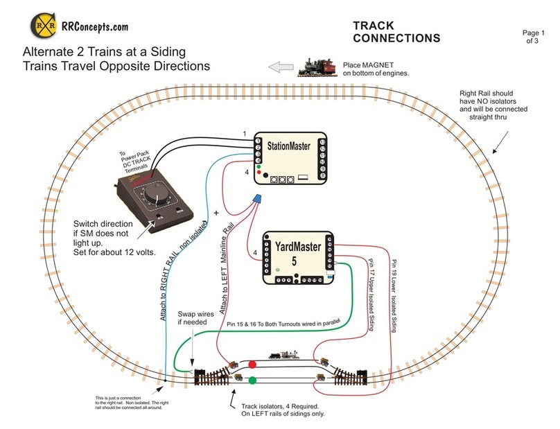
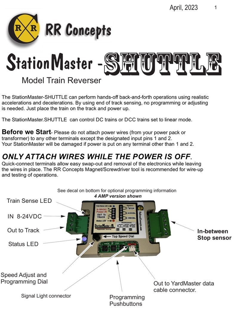
RR-Concepts StationMaster-6 User manual

1
This manual contains detailed hookup and programming instructions for the StationMaster-6 train
controller available in a 4 AMP or 10AMP configuration. The StationMaster-6 can perform station
stops and reversing operations. It can perform all the functions of the StationMaster-5 XL Full Featured
and also contains more advanced hardware and software features described online at StationMaster.net.
The StationMaster-6 can control DC trains or DCC trains set to linear mode.
Before we Start- Please do not attach power wires (from your power pack or
transformer) to any other terminals except the designated input pins 1 and 2.
Your StationMaster will be damaged if power is put on any of the sensor terminals.
ONLY ATTACH WIRES WHILE THE POWER IS OFF.
Quick-connect terminals allow easy swap-out and removal of the electronics while leaving
the wires in place. The RR Concepts Magnet/Screwdriver tool is recommended for wire-up
and testing of operations.
tation aster -
Train Controller
Status LED
Top Speed Adjust and
Programming Dial Out to YardMaster data
cable connector.
IN 8-24VDC
“Justa-station-stop”
connector
Out to Track
Train Sense LED
Programming
Pushbuttons
Sensor Inputs:
Bypass Jumper
DECEL
ACCEL
STOP
SM
April 2023
6
See decal on bottom for optional programming information
External Relay Connector
for signal lights or external
device triggering.
4 AMP version shown
C
RR
RR Concepts

2
Train Detected LED Bypass Jumper
Top Speed Adjust and
Programming Dial “Out to YardMaster” data
cable connector for siding
control hookups.
IN 8-22VDC
Out to Track
See the label on the bottom for programming and additional information.
Sensor LED
Programming
Pushbuttons
Sensor Inputs:
DECEL
ACCEL
STOP
tation aster -
Quick Hookup Instructions
SM6
How to do
Realistic Station Stops &
Realisitic Reversing (More details in manual)
The StationMaster works with DC (out of the box)
or DCC trains set to linear mode. (N, HO, G, etc.)
AC trains cannot be controlled.
sensor
Stopping
Position
To
Power Pack
TRACK
Terminals
To
Power Pack
TRACK
Terminals
Attach to
TRACK.
Swap these
wires to go the
opposite direction
1
2
3
4
8
9
10
11
12
13
StationMaster
Accelerate + Decelerate Station Stop Hookup
1) Attach terminals 1 & 2 to the transformer.
2) Attach terminals 3 & 4 to the track.
3) Attach terminals 8 & 9 to a train sensor. (No polarity)
4) Mount a magnet on an engine or car.
Set the transformer to the desired top speed. That’s it!
See the online manual for optional additional features:
* Change acceleration rate,
* Change deceleration rate,
* Add additional station stops,
* Do multiple laps before stopping,
* Run 2 trains on the same track.
* Change station stop pause duration, (Default 10 seconds)
* Perform “Self-Adjusting” deceleration. (Requires STOP
sensor to stop at an exact location)
To
TRACK
1
2
3
4
8
9
10
11
12
13
StationMaster
SCAN FOR INFO
4 AMP Version shown, Also available in 10 AMP configuration.
StationMaster CONNECTIONS and CONTROLS
Go to StationMaster.net (bottom of page) and download the 25 page user manual for more info.
Visit RailroadConcepts.com for more fun, advanced hookups, and ordering parts.
Un-modified track!
No diodes, no breaks, no additional track connections.
Reversing Hookup
Station Stop Hookup
RR Concepts
C
RR
Un-modified trains.
No sensors, no
magnets.
It just works!
Accelerate + Decelerate Reversing Hookup
1) Attach terminals 1 & 2 to the transformer.
2) Attach terminals 3 & 4 to the track.
3) Program the StationMaster for “Reversing Mode”
(see below for programming)
See the online manual for additional in-between stops,
self adjusting exact stopping using STOP sensors,
delay times, etc,
One time programming for No Sensor Reversing mode”:
1. Turn the top speed dial fully counter-clockwise. 4. When train starts to run, press button #3 about
2. Simultaneously press buttons 1 and 2. 3 feet from the end. Repeat for both directions.
3. Turn the top speed dial fully clockwise. 5. Turn dial to desired creep speed into the ends.

3
Bypass and Manual Reverse Operation
Sometimes automatic control is not desired so the StationMaster-6 contains a bypass feature.
The SM-6 is shipped with a jumper installed on a 2 pin header, however a bypass switch could
easily be installed with a cable that attaches to the header. When the contacts are”open”
the SM will be bypassed to allow manual control. When “closed” the SM will be operational.
External Relay / Signal Light Control
The StationMaster-6 can control external devices when an Auxiliary relay is attached.
The default setting is for a station stop signal light.
When decelerating, creeping, or stopped, the relay will be ON; for all other cases
the relay will be OFF. When a signal light is attached to the relay it could show
RED when entering at the station, and GREEN when leaving.
This relay can also be configured to turn the relay ON or OFF based on the train direction,
or momentarily switch when starting an acceleration or deceleration. This could be used for
station sound affects, etc. See the programming mode page for details.
The SM-6 also allows manual reverse operations. When the input voltage is reverse polarity
(train transformer is backing up train) the StationMaster will disengage and allow manual control.
This means that trains can run under manual control when the direction switch on the
transformer is “reversed”, or the contacts on the header are “open”. This will allow you
to back up trains if needed.
Bypass Jumper
Signal Light Header
Turn connector around
if relay does not work
DPDT Auxilliary relay with cable
Available at RR-Concepts.com
C
RR
RR Concepts

4
StationMaster Basic Hookup Description
The StationMaster is designed to be installed
between the train transformer, and the track.
Attach terminals 1 & 2 to your transformer's DC output (Sometimes labeled
as TRACK) or to a 12-22 volt power source. If using a train transformer
set the throttle position to the desired top speed of the train. If the StationMaster
does not "light up", then the input voltage is reversed OR the bypass jumper
is not in place. The SM-6 contains a DC to DC converter so much higher input
voltages are possible.
Attach terminals 3 & 4 to your track. This is the controlled output voltage that
accelerates and decelerates the train. Pin 3 will be the “common” wire
which is the right rail for Large Scale trains or the left rail for NMRA
standard trains.
Terminals 8 & 9 are the start deceleration sensor input.
When these terminals are closed (sensor detects a magnet) the StationMaster will begin
a decelerate, pause, and then accelerate sequence. The LED will turn WHITE
lfor as long as this sensor is detected. By placing multiple sensors wired in
parallel, the StationMaster can stop at multiple stations on your railroad.
Pressing button #1 will simulate the DECEL sensor operation.
DECEL Sensor
+
+
-
-
Left
Right
Bypass Jumper
C
RR
RR Concepts

5
Terminals 10 and 11 are the optional Start Acceleration sensor inputs.
When these terminals are shorted (sensor detects a magnet) the train will start to accelerate.
This sensor is not necessary unless using “Block Control” or the time delay is set
for maximum blinks. (See below).
Pressing button #2 will simulate the ACCEL sensor.
When programmed for “Blink1: Simple reversing mode” this sensor will perform an
in-between station stop and the ACCEL function will not be operational.
Terminals 12 and 13 are the optional STOP sensor inputs.
ACCEL Sensor
STOP Sensor
When the train is decelerating and these terminals are shorted (sensor detects a magnet), the train
will immediately STOP. This sensor is not necessary unless using the “Creep Stop
Deceleration” mode in which case it is mandatory. A STOP sensor will have no affect unless the train
has already passed over the DECEL sensor.
Pressing button #3 will simulate the STOP sensor.
Optional
C
RR
RR Concepts

6
StationMaster “Deadman Timer”
A unique feature of the StationMaster is the DeadmanTimer.
If a train is sensed on the track and no sensor has been
detected for 10 minutes, the StationMaster will SHUT DOWN
and flash both the Blue train sensed LED and the GREEN
status LED.
This prevents the condition where a train is hung up on an
obstruction and spinning it’s wheels, most probably grinding a
divot in the rails and wearing out wheels and gears.
Each time a sensor is triggered, or the train is not sensed, the deadman
10 minute timer is reset.
The Deadman Timer will be enabled AFTER the first
sensor or pushbutton is pressed after power up.
How to use or bypass the Deadman Timer Shutdown:
* When the sensor connector is pulled and trains are running “manually”,
the Deadman Shutdown will not be enabled, unless a button is pushed.
* To run “manually” and also use the Deadman Shutdown, the DECEL
sensor needs to be pulled, and either the STOP or ACCEL sensor must
be run over.
Flashing Blue LED
Flashing Green LED
Sensor
Connector
C
RR
RR Concepts

7
Top Speed and Programming Mode Dial
The Top Speed dial provides 3 functions:
1: Adjust the top "cruising" speed of the train.
2: Reduce the “creeping speed” when running in Diode Reverse Mode.
3: Enter programming mode.
Top speed adjustment
“Full speed" is clockwise. Turn this dial down as necessary to set the desired cruising
speed of the train. This is only necessary when using a “fixed voltage” power supply
or when a YardMaster is attached and a slow top speed is desired.
Typically, this dial is set fully clockwise and the train throttle (transformer) is used
to set the speed of the train.
Diode Reverse Mode Creep Speed
When in “no-sensor Diode Reversing Mode” turn this dial down to reduce the creeping
speed of the train as it enters the diode sections.
Programming Mode
To enter programming mode turn this dial fully counter-clockwise. The blue Train Detect LED will
“twinkle” to indicate “programming mode”.
The acceleration rate, deceleration rate and time delay can be programmed in this state.
See the programming details or decal on bottom of the StationMaster for additional information.
To exit programming mode turn the dial fully clockwise.
C
RR
RR Concepts

8
Green: train is running.
Fast alternating Red/Green Flashing: train is CREEPING and hunting for
the STOP sensor using the creep speed.
1. Orange NOT flashing, The
StationMaster will ignore next DECEL sensor due to lap counting or block control.
2. Orange Flashing, The StationMaster is performing a time delay.
Red: Train is DECELERATING.
Status LED WHITE flash: A sensor is detected
Both blinking LED's indicate a SHUTDOWN. Red = SHORT CIRCUIT, Green = Deadman
timer. To recover: Turn the top speed dial to zero and then back to 100%, press button #1,
or cycle power. If condition returns after recovery then check for a short circuit
on the track or re-program the shutdown threshold by turning transformer to
full speed, and pressing button #3 while flashing.
A blue Train Sense LED twinkling indicates programming mode.
No color is primary programming mode. A GREEN status LED indicates SECONDARY
programming mode, and a BLUE LED indicates TERTIARY programming mode.
Blue Train Detected LED
Red/Green/Blue STATUS LED
LED indicators
Status LED
Train Sense LED
Status LED
Train Sense LED
Status LED
Train Sense LED
Status LED
Train Sense LED
Status LED
Train Sense LED
Status LED
Train Sense LED
Status LED
Train Sense LED
C
RR
RR Concepts

9
1. Make sure all three sensor inputs are open.
2. If the top speed dial is not already at zero, then turn the top speed dial to zero.
(fully counter-clockwise.) The Blue “Train Detected” LED will “twinkle”
3. Push and hold programming button #1.
4. Watch the status led. Each RED blink will decelerate slower.
Thefastestdecelerationwillbewithoneblink. (TRAIN Stops
sooner) Release the pushbutton when the desired number of blinks have occurred.
A typical number is 5. Repeat this procedure if you want a different value.
One blink corresponds to a 3 second deceleration rate. Each additional blink adds
1 second. For example, a blink count of 5 would result in a deceleration rate of
8 seconds.
When finished with all programming turn the top speed dial fully clockwise and
then turn down to a desired top speed if needed.
All programming values are stored in flash memory and are retained until
re-programmed.
Programming:
Deceleration Rate
Fully
counter
clockwise
C
RR
RR Concepts

10
1. Make sure all three sensor inputs are open. (Red LED is off)
2. If the top speed dial is not already at zero, then turn the top speed dial to zero.
(fully counter-clockwise.) BlueTrain Detected LED will “twinkle”.
3. Press and hold programming button #2..
4. Watch the status led. Each GREEN flash will accelerate slower.
Thefastestaccelerationwillbewithoneblink.
Release the button when the desired number of blinks have occurred.
A typical number is 5. Repeat this procedure if you want a different value.
One blink corresponds to a 3 second acceleration time. Each additional blink adds
1 second. For example, a blink count of 5 would result in a acceleration rate of
8 seconds. A factory default will set to 5.
When finished with all programming, increase the top speed dial clockwise
to MAX and then down to a desired top speed. All programming values are stored
in flash memory and are retained until re-programmed.
A Note on Realistic Accelerations:
* For blinks 1 thru 9 the train will accelerate linearly with the programmed value.
This may be required for some block control operations where a second train is
approaching and the first train needs to quickly accelerate to get out of the way, or for
a trolley which accelerates quickly.
* For blinks 10 and above the train will creep very slowly out of the station
and then continue accelerating as it continues down the main line.
This provides a very realistic operation as a train creeps out of a siding or station
and shows off sound systems with incredible realism.
* 10 blinks will creep for 5 seconds.
* 11 blinks will creep for 10 seconds.
* 12 blinks and up will creep for 15 seconds.
Programming:
Acceleration Rate
Fully
counter
clockwise
C
RR
RR Concepts

11
1. Make sure all three sensor inputs are open. (red Led is off)
2. If the top speed dial is not already at zero, then turn the top speed dial to zero.
(fully counter-clockwise.) BlueTrain Detected LED will “twinkle”.
3. Press and hold programming button #3.
4. Each ORANGE flash will increase the waiting time after a station stop.
A wait time of zero will be with one flash.
Release the button when the desired number of flashes have occurred.
Repeat this procedure if you want a different value.
The LED will turn orange when an infinite delay is set (after 13 counts).
When infinite delay is set, then the ACCEL sensor is required to start up the train
after a station stop.
A fun thing to do would be to connect the ACCEL terminals to a
doorbell switch. Your train would patiently wait until someone pushed the button! Motion
sensors are another possible way to start the train.
When finished with all programming increase the top speed dial clockwise to
maximum or to a desired top speed. All programming values are stored
in flash memory and are retained until re-programmed.
The number of orange FLASHES will correspond to the following
time delays:
1: 0 seconds, no wait.
2: 5 seconds
3: 10 seconds
4 15 seconds
5: 20 seconds
6: 30 seconds
7: 1 minute
8: 2 minutes
9: 5 minutes
10: 10 minutes
11: 30 minutes
12: 60 minutes
13: Infinite, wait for ACCEL sensor. This is for block control operations.
Programming:
Pause Time
Fully
counter
clockwise
C
RR
RR Concepts

12
Programming:
Operating Modes
Please go to RRconcepts.com
to view an informational
video on how to program
operating modes.
BLUE
C
RR
RR Concepts
HOW TO PROGRAM: (Perform a factory reset to clear everything)
1. Enter Secondary Programming mode: (Skip this step if already in secondary programming mode)
* Turn the Top Speed dial fully counter-clockwise to enter programming mode
(Skip this step if already in programming mode).
* Turn the Top Speed dial slowly clockwise until the sensor LED turns green. This indicates
secondary programming mode. This should be about half-way.
2. Press and hold programming button #1 until the desired number of blinks have occurred.
Each blink will set or clear a different feature. If currently ON it will turn off. If ON it will turn OFF.
When finished do not power off without first turning the dial fully clockwise.
Programmable Modes: (Any or all of these or all can be programmed independently)
Hold button for 1 blink = Simple Reversing Mode, ignore next sensor after reversing, ACCEL sensor
will perform an in-between station stop.
Hold button for 2 blinks = Fire YardMaster before acceleration. (Default ON for reversing mode)
Hold button for 3 blinks = Fire YardMaster after train has stopped. (Set after factory reset)
Hold button for 4 blinks = Use automatic train detection to start deceleration. (No-sensor station stops)
Hold button for 5 blinks = Reverse direction before every acceleration. Never ignore sensors.
Hold button for 6 blinks = Only fire YardMaster in forward direction. (For reversing operations with
a siding on one end)
Hold button for 7 blinks = Shut off current sensor. This could cause damage to the StationMaster
unless the transformer can provide short-circuit shutdown. This is sometimes
necessary when running with very small transformers. (1 AMP or less)
Hold button for 8 blinks = Turn on “creep stop”. The train will decelerate then creep until reaching
the STOP sensor. LEDs will flash RED/GREEN when creeping.
When the button is released the StationMaster will echo the currently programmed features (modes)
by blinking the red/green LED 8 times. For example, if “Fire YardMaster after train has stopped” has
been programmed (button pressed for 3 blinks, or after factory reset) and nothing else is programmed
then the StationMaster will blink:
blink 1 RED: Reversing mode is OFF.
blink 2 RED: Fire YardMaster before acceleration OFF
blink 3 GREEN: Fire YardMaster after stopping ON
blink 4 RED: Use train sensor to start deceleration OFF
blink 5 RED: Reverse direction before every acceleration OFF
blink 6 RED: Only fire YardMaster in forward direction OFF
blink 7 RED: Disable current sensor: OFF
blink 8 RED: Creep-stop mode : OFF
Each time a feature is programmed that feature will toggle on or off. (Toggle means the feature will
go OFF if currently ON, or ON if currently OFF). A factory reset will clear all values and set blink 3.
To view the currently programmed operating modes quickly press and release button #1.

13
Additional Information on Programming Modes. The hookup diagrams will identify
which of these need to be set.
blink 1 = Simple Reversing Mode
This will allow reversing operations with a DECEL sensor placed at the ends wired in parallel. After
reversing the very next DECEL sensor will be ignored. In-between station stops can be done by adding
sensors in parallel to the ACCEL terminals. The train will stop at every location where a sensor is placed.
the ACCEL sensor will only provide an in-between stop and will not perform the “accelerate” function.
blink 2 = .Fire YardMaster before acceleration.
If programmed for more than 1 train the YardMaster will fire to the next siding before accelerating
blink 3 = Fire the YardMaster after the train has stopped.
If programmed for more than 1 train the YardMaster will fire to the next siding after the train has stopped.
Note that the StationMaster will automatically set blink 3 after a factory reset
blink 4 = Use automatic train detection to start deceleration.
When a train is sensed entering the track section the StationMaster will start a deceleration sequence.
When programmed for “diode reversing mode” this blink will be set.
blink 5 = Reverse direction before every acceleration
This is similar to blink 1 however the StationMaster will not ignore any sensors and the ACCEL sensor
will be operational.
blink 6 = Only fire YardMaster in forward direction. (only active in reversing mode)
This will allow a reversing operation with sidings on one end.
blink 7 = Disable current sense shutdown.
If a double RED blinking shutdown condition occurs too often then the power supply may be too small to
provide sufficient current and is not reliably sensed by the StationMaster. The shutdown can be disabled
however damage could occur if the transformer does not have short-circuit protection.
blink 8 = Turn on “CREEP STOP” mode.
The train will decelerate using the programmed deceleration rate, then creep until reaching the STOP
sensor. If the STOP sensor is not reached within 25 seconds then the creep speed is increased.
.
C
RR
RR Concepts
13

14
The external auxiliary relay can be programed to behave in four different manners. These include:
* Station Stop mode where the relay will turn on while entering the station and stopped.
* Direction mode where the relay will turn on or off depending on the train direction.
* Trigger mode, where the relay will “pulse” just after stopping.
* Trigger mode where the relay will “pulse” just before accelerating.
HOW TO PROGRAM: (Perform a factory reset to clear everything if needed)
1. Enter Tertiary Programming mode: (Skip this step if already in tertiary programming mode)
* Turn the Top Speed dial fully counter-clockwise to enter programming mode
(Skip this step if already in programming mode). The blueTrain Detected LED will “twinkle”
* Turn the Top Speed dial slowly clockwise until the sensor LED turns Green and then BLUE.
This indicated tertiary programming mode. (Only available on software after 09-2019)
2. Press and hold programming button #3 until the desired number of blinks have occurred.
When finished do not power off without first turning the dial fully clockwise.
Programmable Modes:
Hold button for 1 blink = Station Stop mode,
Hold button for 2 blinks = Direction mode
Hold button for 3 blinks = Pulse at stop
Hold button for 4 blinks = Pulse at acceleration start
To view the currently programmed operating mode quickly press and release button #3.
Programming:
Aux Relay Control
Please go to RRconcepts.com
to view an informational
video on how to program
operating modes.
BLUE
C
RR
C
RR
RR Concepts
Additional notes for usage:
* The “pulse” modes could be used to trigger an external sound module or other device.
* It is also possible to use this header to directly trigger another StationMaster or YardMaster
without the relay. For example, just as one StationMaster stops a train it could then trigger
a second StationMaster to start up. Consult RR concepts for details.

15
Programming:
Factory Reset
To set the StationMaster back to factory defaults perform the following:
1: Enter programming mode by turning the top speed dial fully counter-clockwise
2. Press and hold both button #1 AND button #3 at the same time.
3 Turn the top speed dial fully clockwise to exit programming mode.
Do not power off without first turning the dial fully clockwise.
Fully
counter
clockwise
C
RR
RR Concepts
The factory default settings are:
* Acceleration rate 5 blinks
* Deceleration rate 3 blinks.
* Time delay 5 seconds.
* Train count: 2 (Note: Block control will not be operation until set for 1 train)
* Lap count: 1
* Operating mode (features):
Blink 1 = RED, Simple Reversing: OFF.
Blink 2 = RED, Fire YardMaster before accelerating: OFF
Blink 3 = GREEN, Fire YardMaster after train has stopped: ON
Blink 4 = RED, Use train sense to start deceleration: OFF
Blink 5 = RED, Reverse before every acceleration: OFF
Blink 6 = RED, Fire YardMaster only in forward direction: OFF
Blink 7 = RED, Disable current sensor: OFF
Blink 8 = RED, Enable CREEP-STOP mode: OFF
With these settings both the Simple Station Stop, and
the Alternating Trains hookups are ready to run!

16
1. Turn the Top Speed dial fully counter-clockwise to enter programming mode
(Skip this step if already in programming mode).
2. Slowly turn the Top Speed dial clockwise until the GREEN LED turns on. This indicates
secondary programming mode.
(Skip this step if already in secondary programming mode)
3. Press and hold button #2.
4. Count the blinks while the button is pressed. Release the button when the
appropriate number of blinks (LAPS) are set.
When finished with all programming turn the top speed dial clockwise to maximum.
All programming values are stored in flash memory and saved until re-programmed again.
Programming:
MULTIPLE LAPS
Blue
C
RR
RR Concepts

17
The train count is needed for 3 reasons:
1. Manage different creeping speeds for up to 5 trains.
2. Send proper signals to attached YardMasters to correctly fire turnouts.
3. Allow running in a block-control mode. (Must be set for 1 train)
For example, a 3 track siding using 2 YardMasters wired in parallel would
have a train count of 3, since 3 trains will be controlled.
A factory reset will set this to 2 trains.
For an alternating siding hookup a factory reset will set this correctly.
Programming:
1. Make sure all three sensor inputs are open.
2. If not already in programming mode turn the top speed dial to zero.
(fully counter-clockwise.)
3. Slowly turn the top speed dial clockwise until the sensor LED turns GREEN.
This indicates secondary programming mode.
(Skip this step if already in secondary programming mode)
4. Press and hold button #3.
5. Each orange flash counts the number of running trains.
Release the button when the desired number of flashes have occurred.
The number will be echoed back when the button is released..
Repeat this procedure if you want a different value.
When finished with all programming, increase the top speed dial clockwise to MAX,
and then down to a desired top speed if necessary.
All programming values are stored in flash memory and saved until re-programmed again.
NOTICE: A factory reset will set the train count to 2. Block control will not be
operational until set for 1 train.
Programming:
Train Count
Blue
C
RR
RR Concepts

18
“Justa Station Stop”
Justa-Station-stop performs a decelerate/Pause/Accelerate sequence without
triggering an attached YardMaster or reversing.
When operating in an alternating trains hookup, additional stations stops can be done
at different locations around the loop without affecting the parked train.
Add a 3 pin plug into the bottom right 3 pin header and attach the sensor to pins 1 and 3.
The Deceleration rate, Acceleration rate, and pause times are FIXED.
Cut off pin end to expose wires.
Attach sensor to wires 1 & 3
JUSTA-STATION-STOP
connector
C
RR
RR Concepts

19
To
Power Pack
DC TRACK
Terminals.
If StationMaster does not turn on
then reverse direction on transformer.
To
TRACK
Diode Isolators (two places)
No Sensor Reversing Hookup
The StationMaster-6 can operate in a reversing back-and forth mode using either
sensors to detect the train, or diodes on the ends without sensors.
Diodes can be attached in any fashion, or LGB 10151 units could be use in place of diodes.
PROGRAMMING:
1. Go to programming mode. (Turn the speed dial full counter-clockwise)
2. Press buttons #1 and #2 at the same time.
3. Exit programming mode. (Turn the speed dial full clockwise)
- To return to normal operations perform a factory reset -
Reversing using Diodes
1
Diodes can be wired to the track using self-tapping screws, or attached to an isolator.
A 1 AMP diode is usually sufficient since the diodes would be flowing current for a very
short amount of time.
continued...
1
2
3
4
8
9
10
11
12
13
StationMaster
Here is the hookup:
* 2 wires from the transformer to the StationMaster.
* 2 wires from the StationMaster to the track.
* Diodes on the ends where the engine will stop.
C
RR
RR Concepts

20
OPERATIONS:
The Reverser has a 2 step speed profile and accelerates/decelerates to these speeds. Speed #1 is the
top speed of the train set by the transformer. Speed #2 is a “creeping” speed which allows the train to
always reach the diode isolators on the ends. Speed #2 (creeping speed) is set by the dial.
The Reverser will accelerate using the programmed acceleration rate, maintain a top speed, and then
decelerate down to Speed #2 when the TIME TO DECELERATE time is reached.
Once the deceleration has completed, Speed #2 will be maintained for the duration of the “pause time”,
or keep running for as long as the train is sensed on the track. This provides a very realistic and smooth
operation. After a reverse, the operation is repeated.
Do This Once:
1 Set the transformer for the desired top speed of the train and turn the StationMaster top speed dial
fully clockwise.
2 Watch the train and press BUTTON #3 when the train reaches the TIME TO DECELERATE location.
The StationMaster will show non-flashing BLUE when button #3 must be pressed. This location is
typically 2 or 3 feet from the ends, but depends on the speed of the train and the programmed deceleration
rate. After pressing the StationMaster will decelerate into the diodes. Repeat for the other direction.
Notice that the StationMaster will store a different TIME TO DECELERATE value for each direction since
trains don’t always go the same speed in forward and reverse, and there could be hills! Button #3 will
need to be pressed THREE times, and will display solid BLUE when it must be pressed.
3 To erase the stored time values and start over: Press button #1.
That’s it!
Dial: - optional -
Turn counter-clockwise
to creep slower.
Note: Turning too far will enter
programming mode.
.
Continued...
No-Sensor Diode Reversing Mode, Continued...
Pushbutton Operations
Button 1:
Reset all times. (start over) Button #3:
Start deceleration NOW.
C
RR
RR Concepts
Table of contents
Other RR-Concepts Toy manuals
Popular Toy manuals by other brands

REVELL
REVELL Lockheed Martin F-16MLU Solo Display Assembly manual

SIKUCONTROL32
SIKUCONTROL32 6777 John Deere 7R with Frontlader operating instructions

SOARING MODELS
SOARING MODELS Kite Assembly instruction

Faller
Faller ENZIAN HOUSE quick start guide

LEGO
LEGO Architecture Instructions for use

Mattel
Mattel Mega Construx Despicable Me DYG41 instructions

REVELL
REVELL Boeing 737-200 British Airways Assembly instructions

Educational Insights
Educational Insights CoinStruction EI-4030 Castle manual

Eduard
Eduard Zoom AV-8B Harrier II manual

TILLIG BAHN
TILLIG BAHN BR 112.1 manual

Mega Bloks
Mega Bloks KAPOW! NOX 94201 manual

MGA
MGA Miniverse Make It Mini Kitchen manual