e-motion SCA-SS-70-10 User manual

Manual SCA-SS-70-10 V 2.301/04page 1
e-motion Gesellschaft für Antriebstechnik mbH, Zettachring 2, D-70567 Stuttgart, Germany
Tel.:+49-(0)711-7221535, Fax.:+49-(0)711-7221548 E-mail:mgmt@e-motion-controls.com
SCA-SS-70-10 (70V, 10A)
The servo-amplifier SCA-SS-70-10 is a powerful PWM-module for brushed DC motors with an output range
up to 700 Watt.
Six operation modes are integrated
•Torque-control
•IxR-control
•DC-Tacho control
•Speed-control by digital-encoder feedback
•Voltage control
•Analog positioning
The required operation mode is to be selected from the front side of the module by setting jumpers. This
SCA-SS-70-10 servo amplifier is protected against over current overheat and short-circuit of the output
stage against each other or to the power supply. By the usage of advanced technology and power-MOS-
FETs a high efficiency up to 95 %. An integrated choke in combination with the high PWM-frequency of 49
kHz enables the usage of motors with low inductance. In most cases no external choke is required
additionally. Due to the wide range of power supply voltage between 11 to 70 V DC the SCA-SS-70-10 can
be used very flexible with different kinds of power supplies within many applications. The robust aluminium
case has been constructed for different methods of mounting it, therefore a fast and easy integration is
provided. screw terminals and a durable controller-design allow a fast and straightforward commissioning.

Manual SCA-SS-70-10 V 2.301/04page 2
e-motion Gesellschaft für Antriebstechnik mbH, Zettachring 2, D-70567 Stuttgart, Germany
Tel.:+49-(0)711-7221535, Fax.:+49-(0)711-7221548 E-mail:mgmt@e-motion-controls.com
Contents
1. Safety notes...................................................................................................................................... 2
2. Specification..................................................................................................................................... 3
3. Operating modes.............................................................................................................................. 4
4. Commissioning................................................................................................................................. 6
5. Description of inputs and outputs................................................................................................... 7
6. Troubleshooting............................................................................................................................. 10
7. Dimensions..................................................................................................................................... 10
8. Versions of text............................................................................................................................... 11
1. Safety notes
1.1. Skilled personnel
installation and commissioning have to be done only by skilled personnel
1.2. Laws
The user has to ensure the correct installation of the servo amplifier and additional equipment
according to valid laws and rules.
1.3. Remove load
For first commissioning the motor should run with free shaft which means without load.
1.4. Additional safety components
Electronic components are not free of failure or damage. Therefore plants have to be installed with
additional device and installation protecting components. A safe and stable state has to be ensured in
the case of damage of some devices, wrong handling, cable disruption and other cases of any kind of
malfunction.
1.5. Repairs
Repairs have to be done only by authorized distributors or at the manufacturer. Unauthorized opening
and improper repairs of the device may cause danger to the user and the plant.
1.6. Danger
Care about having no power supply voltage all around the plant during installation of the device!
Never touch any voltage-carrying components!
1.7. Maximum input voltage
The input power supply voltage must not exceed 70 V DC. Voltages exceeding 70 or reversed
connection will destroy the unit.
1.8. ESD
Do not touch any of the contacts of the device.

Manual SCA-SS-70-10 V 2.301/04page 3
e-motion Gesellschaft für Antriebstechnik mbH, Zettachring 2, D-70567 Stuttgart, Germany
Tel.:+49-(0)711-7221535, Fax.:+49-(0)711-7221548 E-mail:mgmt@e-motion-controls.com
1.9. EMC
the SCA-SS-70-10 is corresponds to the EC directives, standards and regulations 89/336/EWG article
10 and appendix 1 (EMV) amended by 92/31/EWG and 93/68/EWG and meet the requirements with
standard EN 61800-3 (1996) if the following directions are observed:
•usage of a zinc plated mounting plate, well connected to earth
•mounting of the drive by usage of toothed washers
to get a save electrical connection to „Power GND“/ Earth .
•usage of shielded cables (less then 10m) to and from the unit
•large area contact of the shielding with zinc plated mounting plate.
•motor housing properly connected to earth
the user have to consider application specific features
2. Specification
Power supply voltage 11-70 V DC
Current (impulse) 20 A
Current (nominal) 10 A
Frequency of power output stage 49 kHz ( +-10%)
Efficiency 95 %
Bandwidth of current controller 2,5 kHz
2.1. Electrical
data
Internal choke 370 µH
Set value -10...+10 V
Encoder input signals Channel A, B; TTL max. 100 kHz
Tacho Max 50 VDC(100kOhm)
Enable Enable 8-30 V
limit switch „Disable Rev“ Disable 8-30 V
2.2. Inputs
limit switch „Disable Fwd“ Disable 8-30 V
Current monitor „Monitor I“ 0,5V/A
Speed monitor „monitor n“ 0,1V/V
Supervision output Ready Open Collector max. 30 V DC
Supervision output Error Open Collector max. 30 V DC
Auxiliary voltage source –15 V 20mA max. 20mA
Auxiliary voltage source +15 V 20 mA max. 20 mA
2.3. Outputs
Auxiliary voltage source +5 V 100 mA Voltage supply for encoders
2.4. Display 2-colour LED Green: ready red: error
2.5. Weight With terminal connector 650 g
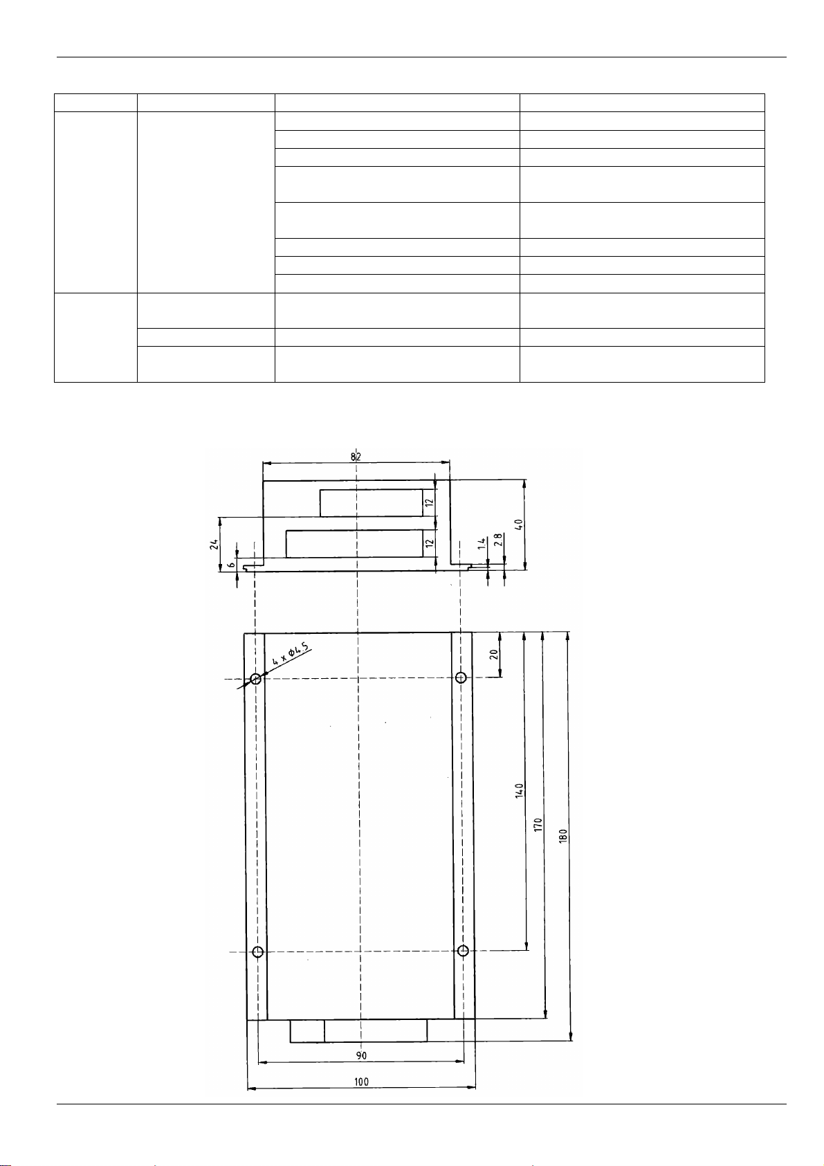
2.6. Dimensions (DxWxH) 180 x 100 x 40 mm
Operation -10...+45oC
2.7. Temperature-
range Storage -40...+80oC
2.8. Humidity
range Non condensing 20% -80% rel. hum.
Manual SCA-SS-70-10 V 2.301/04page 4
e-motion Gesellschaft für Antriebstechnik mbH, Zettachring 2, D-70567 Stuttgart, Germany
Tel.:+49-(0)711-7221535, Fax.:+49-(0)711-7221548 E-mail:mgmt@e-motion-controls.com
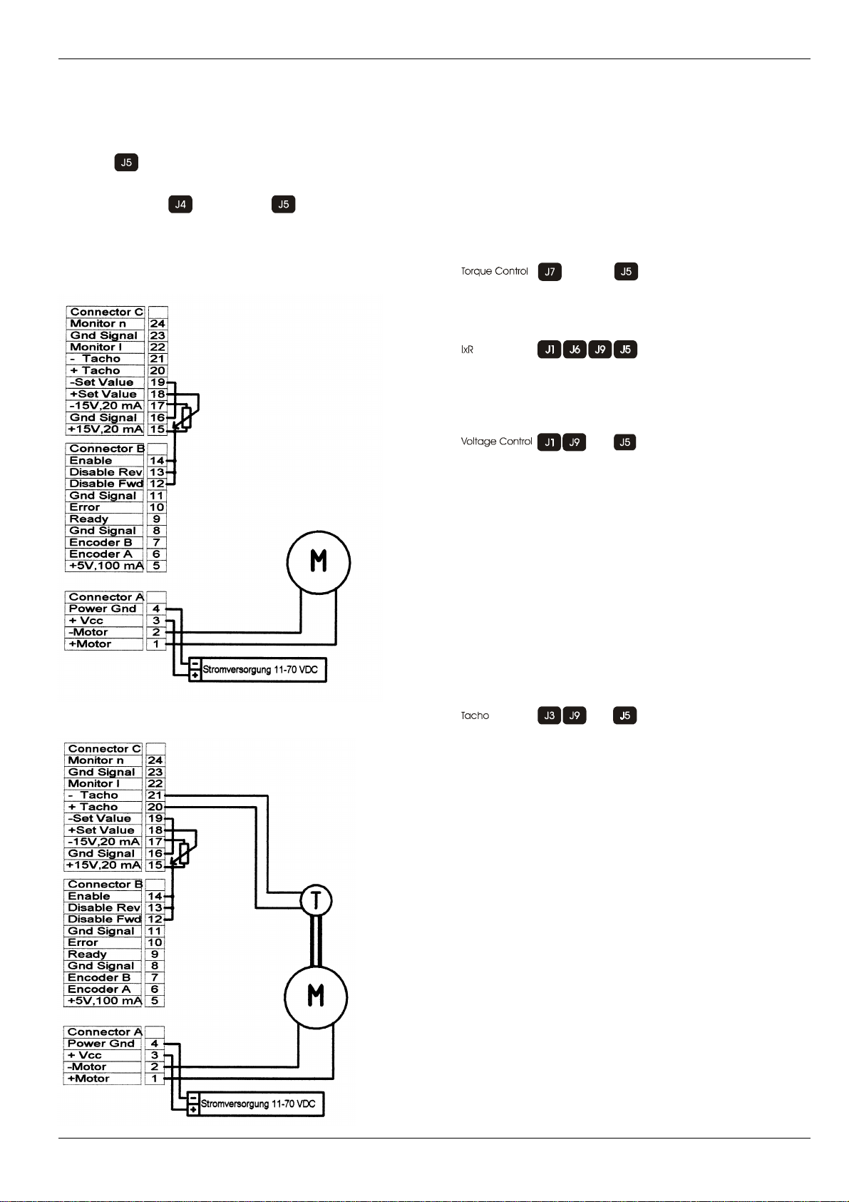
3. Operating modes
wiring
For use with external potentiometer set the
jumper .Apotentiometer of 10 kOhm value is
to be used.
Set the jumper instead of to control the
set value with the internal OFFSET potentiometer.
Torque Control IxR Voltage Control
( shown with ext. Poti 10k )
Tacho
Jumpers to be placed
Required selection of:
•Operating Mode
•Imax
•Input for Set Value
Aktive Potentiometer:
nmax, Imax, Offset
Aktive Potentiometer:
Gain, nmax, Imax
Offset, IxR
Aktive Potentiometer:
Gain, nmax, Imax
Offset
Active potentiometer:
Gain, nmax, Imax, Offset
Manual SCA-SS-70-10 V 2.301/04page 5
e-motion Gesellschaft für Antriebstechnik mbH, Zettachring 2, D-70567 Stuttgart, Germany
Tel.:+49-(0)711-7221535, Fax.:+49-(0)711-7221548 E-mail:mgmt@e-motion-controls.com
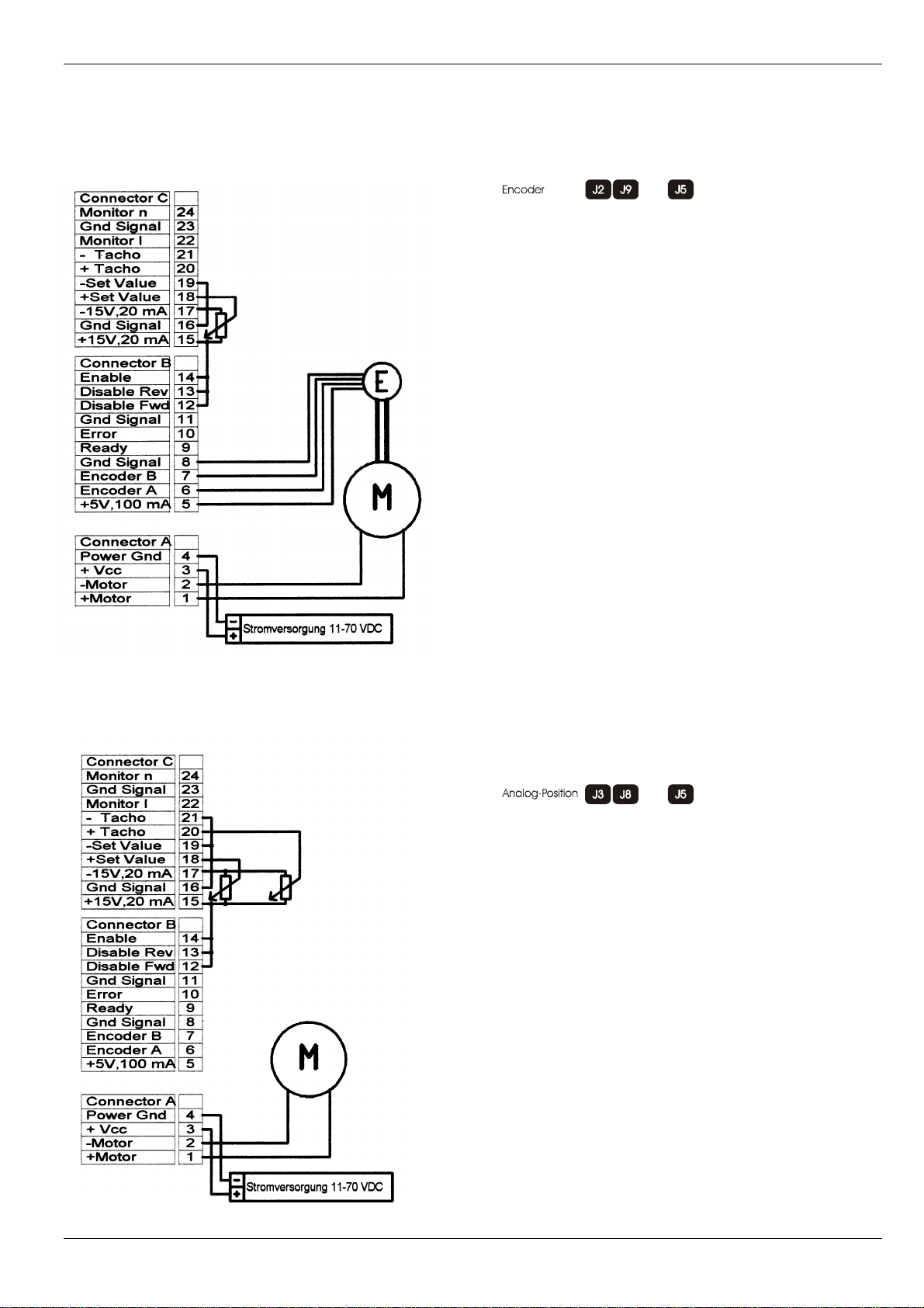
Encoder
Analog Position
Active potentiometers:
Gain, nmax, Imax, Offset
Active Potentiometers
Gain, nmax, Imax

Manual SCA-SS-70-10 V 2.301/04page 6
e-motion Gesellschaft für Antriebstechnik mbH, Zettachring 2, D-70567 Stuttgart, Germany
Tel.:+49-(0)711-7221535, Fax.:+49-(0)711-7221548 E-mail:mgmt@e-motion-controls.com
4. Commissioning
4.1. Selection of power supply
Any power supply can be used as long the minimal requirements listed below are fulfilled. We
recommend to remove the motor from the mechanical construction to avoid damage and danger by
uncontrolled movements.
Requirements to the power supply:
Output voltage: min. 11 V DC max. 70 V DC
Residual voltage: < 5 %
Output current: 10 A nominal, 20 A peak
4.2. Function of the potentiometers
Potentiometer Function Turning ccw Turning cw
Gain Gain adjustment Decreasing Increasing
N max Maximum speed at set value of
10 V Decreasing speed Increasing speed
I max Current limitation Decreasing min. 0,3 A Increasing max 10 A
IxR IxR compensation low compensation High compensation
Offset adjustment n=0 at set value= 0 Motor turns cw Motor turns ccw
4.3. Presetting of potentiometers
Original delivered servo amplifiers are adjusted to uncritical values and for easy adjustment by the
user.
4.4. Adjustment 1.
Adjust max. set value (e.g. 10 V) and turn potentiometer n max cw til the
required speed is reached
2. Adjust potentiometer Imax to required value of current limitation.
Important: Refer to motor manufacturers data sheet
3. Turn potentiometer Gain slowly cw until the required gain is reached
Important: If the motor turns rough, is vibrating or makes noise turn
potentiometer ccw again, until the instability of the system is obsolete.
4. Adjust set value = 0V and adjust potentiometer Offset until the motor stops
to speed 0.
IxR-control
DC-Tacho control
Digital-Encoder control
Voltage adjustment
Analog positioning
5. Additionally only at IxR compensation:
increase slowly Poti IxR, until the value of the feedback is high enough to
control the drive to get best results concerning motor speed at different
loads
Torque control
1. Adjust potentiometer Imax to required value of current limitation.
Important:: Refer to motor manufacturers data sheet
Manual SCA-SS-70-10 V 2.301/04page 7
e-motion Gesellschaft für Antriebstechnik mbH, Zettachring 2, D-70567 Stuttgart, Germany
Tel.:+49-(0)711-7221535, Fax.:+49-(0)711-7221548 E-mail:mgmt@e-motion-controls.com
4.5. Commissioning
Select the required operating mode by setting the according jumpers on the left side of the unit. Refer
to the printing on the front plate.
Required selection of:
•operating mode
•output current range
•Input for set value
Connect motor, control inputs e.g. set value, enable and if necessary an additional encoder or tacho
to the drive.
Connect power supply.
Enabling and adjustment referring to manual.
5. Description of inputs and outputs
pin number in ( )
5.1. Inputs
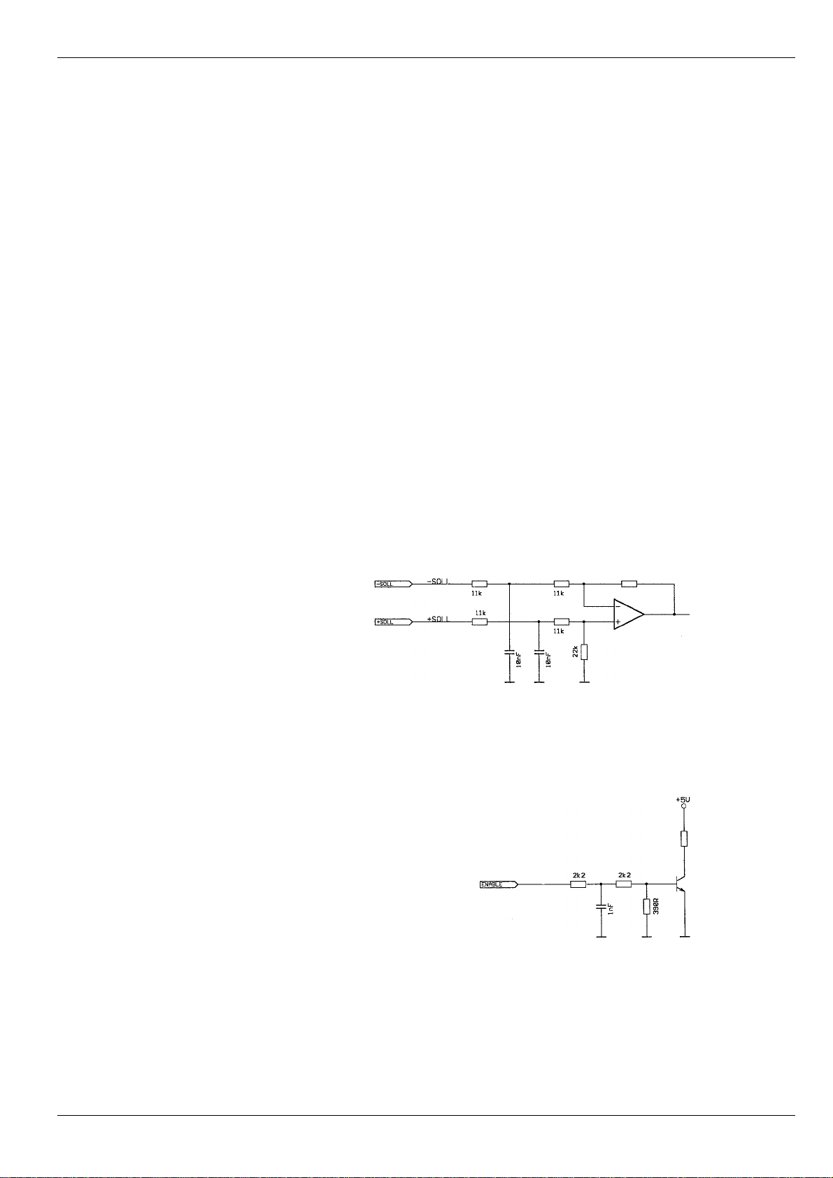
5.1.1.Set value (18,19)
The input for set value is internally connected to an differential amplifier.
Input range of set value: -10 V...+10 V
Input impedance: 20 kOhm
Definition of polarity: positive set value (+Set value) > (-Set value)
negative set value (+Set value) < (-Set value)
5.1.2.Enable (14)
High potential at the input enable will activate speed/torque control and voltage will be applied to the
motor winding. Leaving this input open or pulling it to GND-potential will result in disabling the unit
5.1.3.Disable Fwd (12)
5.1.4.Disable Rev (13)
these direction depending inputs have to be connected directly or via a NC to high potential. If not
connected or connected to GND the unit will be disabled at the corresponding set value.
Manual SCA-SS-70-10 V 2.301/04page 8
e-motion Gesellschaft für Antriebstechnik mbH, Zettachring 2, D-70567 Stuttgart, Germany
Tel.:+49-(0)711-7221535, Fax.:+49-(0)711-7221548 E-mail:mgmt@e-motion-controls.com
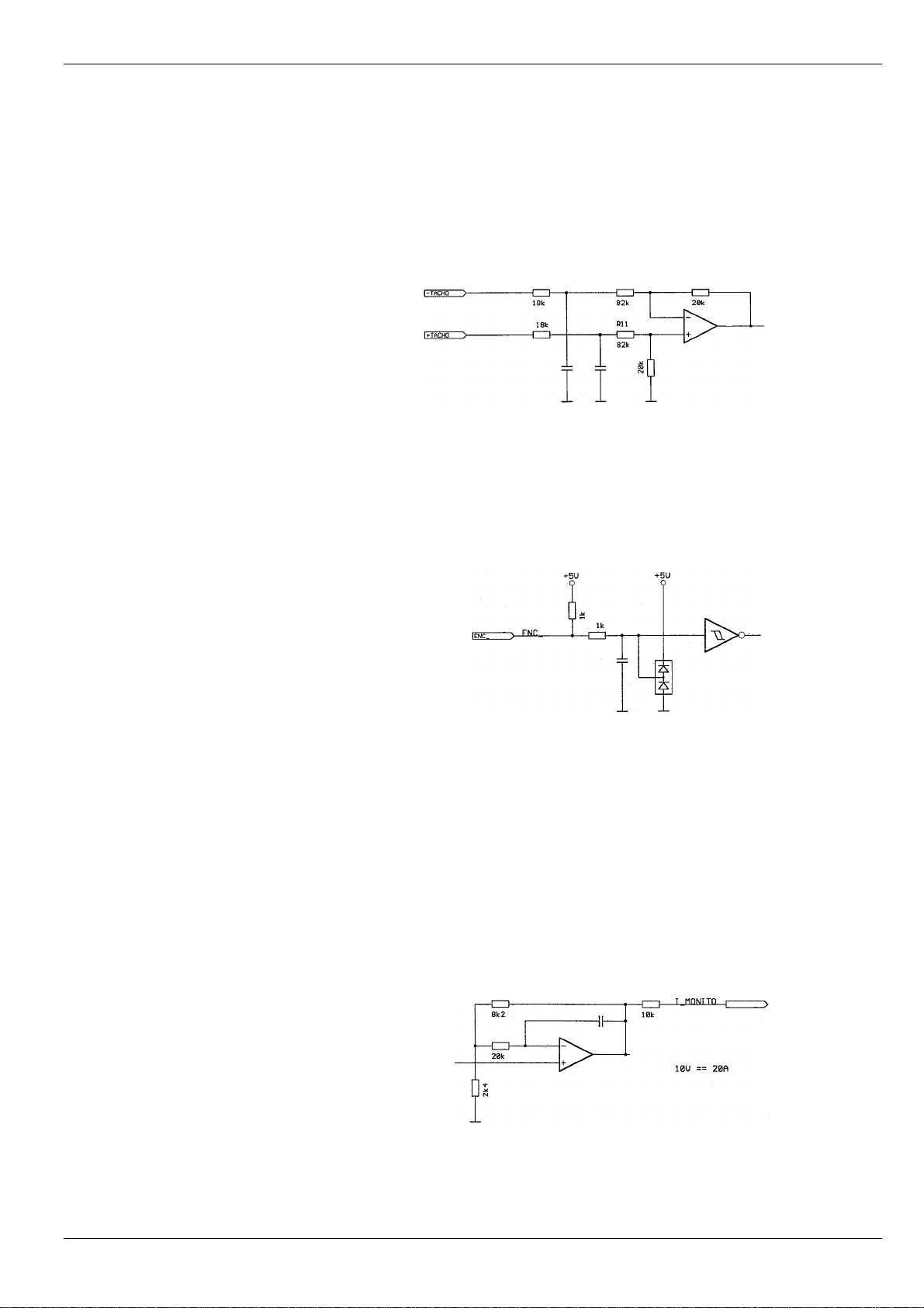
5.1.5.–Tacho (21)
5.1.6.+Tacho (20)
for operating mode tacho control an analog tacho has to be connected to these inputs.
Input Impedance: 100 kOhm
Maximum input voltage 50 V
Important at cw turning of motorshaft the potential of the signal +Tacho has to be higher than the
potential of -Tacho to close the control loop.
5.1.7.Encoder A (6)
5.1.8.Encoder B (7)
The inputs encoder A, B are to be connected to the corresponding outputs of the encoder in operating
mode speed control with encoder feedback.
5.1.9.Power Gnd (4)
5.1.10. +Vcc (3)
Power supply connection.
Caution: DO NOT connect: +VCC or Power Gnd to the outputs Motor A, B or C
5.2. Outputs
5.2.1.Current monitor Monitor I (22)
A current monitor for supervisional purposes is integrated to the servo amplifier. The output provides
an analog signal (voltage) which is proportional to the motor current.
The monitor output is short circuit proof
Output range: -10 V...+10 V
Output impedance: 10 kOhm
Output proportionality : 0,5V/A

Manual SCA-SS-70-10 V 2.301/04page 9
e-motion Gesellschaft für Antriebstechnik mbH, Zettachring 2, D-70567 Stuttgart, Germany
Tel.:+49-(0)711-7221535, Fax.:+49-(0)711-7221548 E-mail:mgmt@e-motion-controls.com
5.2.2.Speed monitor Monitor n (24)
A speed monitor for supervisional purposes is integrated to the servo amplifier. The output provides
an analog signal (voltage) which is proportional to the motor speed.
It can be used for qualitative weighting of the dynamic of the drive system.
Output range: -10 V...+10 V
Output impedance: 10 kOhm
Output proportionality: ca. 0,1 V/V
5.2.3.Supervision signal Ready (9)
The ready-signal is to show the status of the drive and can be used to provide a feedback signal to
other devices and controls. The open-collector output is normally turned on which means the output is
pulled to GND if there is no fault within the drive system. In the case of a fault like under voltage, over
voltage, overheat or over current the internal transistor is high impedance, the output is pulled to a
positive level by an external connected resistor.
Input range max. 30 V DC
Load current < 20 mA
5.2.4.Supervision signal „Error“ (10)
The error-signal is to show the status of the drive and can be used to provide a feedback signal to
other devices and controls. The open-collector is normally turned off which means the output is pulled
to a positive level by the means of an external resistor. In the case of a fault like under voltage, over
voltage, overheat or over current the output is pulled to GND.
Input range max. 30 V DC
Load current< 20 mA
The outputs „Error“ and „Ready“ are inverse to each other.
Any fault is stored and can be reset by enable off and on.
5.2.5.-Motor (2)
5.2.6.+Motor (1)
motor connection
Manual SCA-SS-70-10 V 2.301/04page 10
e-motion Gesellschaft für Antriebstechnik mbH, Zettachring 2, D-70567 Stuttgart, Germany
Tel.:+49-(0)711-7221535, Fax.:+49-(0)711-7221548 E-mail:mgmt@e-motion-controls.com
6. Troubleshooting
Symptom Operating mode Causes Repair
Power supply voltage < 11 V Check power supply
Enable not active Check level at pin 12-14
Set value 0V Check set value
Current limitation adjusted too low Check potentiometer adjustment
I max
Speed range too low Check potentiometer adjustment n
max
Wrong operation mode Check jumper setting
Bad connections Check connectors
Motor
does not
turn
All
Wrong wiring Check wiring
Speed control
encoder feedback Encoder signals Check signals and sequence
Tacho mode Tacho signals Check voltage and polarity
No speed
control
IxR Feedback too low Check adjustment of
potentiometer Gain and IxR
7. Dimensions

Manual SCA-SS-70-10 V 2.301/04page 11
e-motion Gesellschaft für Antriebstechnik mbH, Zettachring 2, D-70567 Stuttgart, Germany
Tel.:+49-(0)711-7221535, Fax.:+49-(0)711-7221548 E-mail:mgmt@e-motion-controls.com
8. Versions of text
V2.2(09/00) additional information input and output signals
V2.3(01/04) save electrical connection to „Power GND“/ Earth EMV, use of shielded Cables
(less then 10m) to and from the unit,
Table of contents
Other e-motion Amplifier manuals


