EA3GCY EGV-9B v1 User manual

EGV-9B 80 to 10m QRP CW Transceiver Kit Page 1
EGV-9B v1
80 to 10m QRP CW Transceiver KIT
MAIN BOARD
Assembly manual
Last update March 01, 2023
ea3gcy@gmail.com
Latest updates and news in: www.ea3gcy.com
Thank you for building the EGV-9B v180 to 10m QRP CW Transceiver kit
Have fun assembling it and enjoy QRP! 73 Javier Solans, EA3GCY

EGV-9B 80 to 10m QRP CW Transceiver Kit Page 2
INTRODUCTION
This EGV-9B transceiver is probably the kit that I have produced with more care and illusion in my life.
It is a great honor to name this kit "EGV", the callsign suffix of the late Miguel Montilla, EA3EGV (SK).
With no doubt, this is the kind of kit he liked most.
It was my privilege to establish and share with him the first years of the EA-QRP Club. He has always
been a referent in my life; when I remember those wonderful years his humbleness, work capacity and
generosity are the virtues which shine his image.
How lucky I was to be able to share the path with you, Miguel. Thanks! Javier Solans, ea3gcy
Miguel Montilla, EA3EGV (SK)
Miguel got his A class callsign in 1983. He hold previously the call EC3BAY. He was a good CW
operator, highly respected among their peers. Holder of many awards and winner of several contests,
Miguel enjoyed both the competition and sharing his time with a novel operator, patiently providing
information to make a QSO.
He published articles on the journal from URE (Spanish Radio Amateur Union) Unión de
Radioaficionados Españoles, on “CQ Radio Amateur” (Spanish edition) and on the G-QRP bulletins, etc.
But, without doubt, what he liked most it was QRP kit building. He loved to build a kit over a weekend
and enjoy some placid QSOs made with his new fresh transceiver. Of course, always with the minimum
power required!
Miguel EA3EGV was the founder member #1 of the EA-QRP CLUB.
On September 1994 a group of four hams, Miguel Montilla EA3EGV, Miguel Molina EA3FHC, Vicenç
Llario EA3ADV and myself, Javier Solans EA3GCY, founded the EA-QRP.
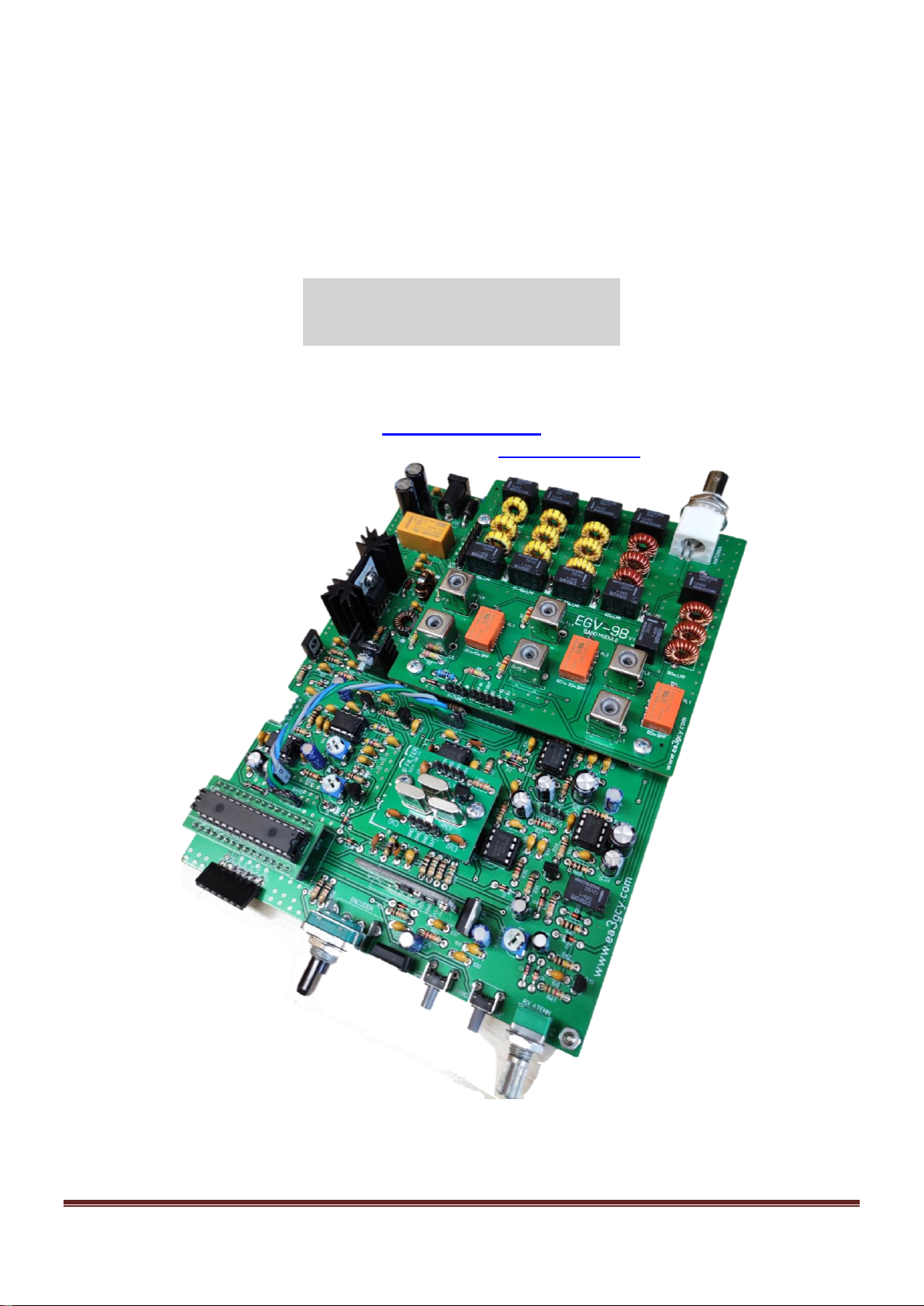
EGV-9B
The EGV-9B is the evolution of the legendary EGV+ kit.
The EGV-9B is a 80 to 10m QRP CW transceiver design based on the NE602 integrated circuit used as
a receiving mixer and CW demodulator. Band and TX / RX switching, audio mute etc. they are controlled
by an ATMEGA328 processor (Arduino NANO compatible).
The EGV-9B is a very versatile design. To facilitate assembly and experimentation, the circuit is
developed on a main board and a plug-in board with the low-pass and band-pass filters. The Local
Oscillator, BFO and CW TX signal are generated by a SI-5351 module that is controlled by the
ATMEGA328 processor. Frequency and other performance data is displayed on a 1.3 "OLED screen.
The CW transmit signal is generated and keyed directly, there are no heterodyning or mixing with other
signals. The IF crystal filter is also mounted on a small plug-in board, which makes experimentation
easier.
The EGV-9B includes features like CW keyer and beacon, audio Mute, six frequency steps in two
ranges, S-Meter and RIT. Separate adjustments for headphone, speaker, RX volume, and sidetone
volume. Setting menus for BFO, SI5351 Xtal adjust, voltmeter adjust etc.
There are only five controls: Frequency tuning, Band tuning, Volume, RF attenuator and two UP-DOWN
band switches.
KB-2 automatic keyer circuit is included on EGV-9B board. It offers iambic A and B mode, 4 memories
and various settings (speed adjustment, adjustable lateral tone, tune function, beacon, straight keyer,
etc).

EGV-9B 80 to 10m QRP CW Transceiver Kit Page 3
Note: good experience on radio assembly is required.
It shouldn't be your first transceiver to build.
All SMD parts soldered at the factory. You don't have to solder anything SMD
SPECIFICATIONS
GENERAL:
Frequency coverage:
80-60-40-30-20-17-15-12-10m
Note: You can tune below and above the bands (from 3 to 30MHz) but downgrading the characteristics
Tuning steps on two ranges: 10Hz-100Hz-1kHz and 10kHz-100kHz-1MHz.
Modes: CW.
RIT function: Without frequency limit
Power requirements: 10 –14VDC, 1 –2A transmit, 0.15 –0.25A receive.
Antenna impedance: 50 ohms nominal.
Controls: Tuning with pushbutton. Band-pass adjust. Volume. RF attenuator. UP-DOWN band switches.
Board dimensions: 180 x 140 mm.
Weight: (no enclosure): 0.35 kg.
TRANSMITTER:
Mode: CW (direct frequency, without heterodyning or mixing)
RF output: 3 to 6W @13.8V (depends on band)
Output TX Amp: C class amplifier.
Harmonics output: -45dBc or better below the fundamental frequency (excepted 60, 17 and 12m)
Other spurious signals: -50dBc or better below the fundamental frequency.
60, 17 and 12m bands: The attenuation of harmonics signals are not so good.
T/R switching: Relays.
RECEIVER:
Type: Superheterodyne. Balanced mixers.
Sensitivity: 0.4uV minimum discernible signal average (according band).
Selectivity: 3-pole crystal ladder filter, 800Hz nominal bandwidth.
IF frequency: 4.915MHz.
AGC: acts on the receive path according to the received audio level.
Audio output: 250mW, 4-8 ohms.
PLEASE READ ALL ASSEMBLY INSTRUCTIONS COMPLETELY AT
LEAST ONCE BEFORE YOU BEGIN.

EGV-9B 80 to 10m QRP CW Transceiver Kit Page 4
LIST OF COMPONENTS BY VALUE/QUANTITY
Resistors list
Qty
Value
Checked
Ref.
Identified
4
10 Ω
R7, R14, R46, R47
brown-black-black
4
22 Ω
R23, R24, R32, R34
red-red-black
10
100 Ω
R1, R2, R3, R8, R16, R19, R39, R45, R49, R50
brown-black-brown
2
150 Ω
R15, R17
brown-green-brown
1
330 Ω
R22
orange-orange-brown
3
470 Ω
R13, R33, R43
yellow-violet-brown
6
1K
R10, R20, R27, R35, R37, R48
brown-black-red
1
1K5
R41
brown-green-red
1
2K2
R21
red-red-red
2
4K7
R5, R6
yellow-violet-red
21
10K
R4, R9, R11, R12 R18, R25, R36, R40, R44, R52, R53,
R54, R55, R56, R57, R58, R59, R60, R61, R62, R63
brown-black-orange
1
22K
R51
red-red-orange
5
100K
R26, R28, R29, R30, R42
brown-black-yellow
2
220K
R31, R38,
red-red-yellow
Potentiometers list
2
100
Adjustable RM-063 P6, P7
103
2
10K
Adjustable RM-065 P1, P2
101
1
100K
Adjustable RM-065 P5
104
1
1K
Shaft potentiometer P3
B1K
1
10K
Shaft potentiometer P4
B10K
Encoder
1
Encoder
PEC16-4015F Encoder
--
Capacitors list
Qty
Value
Checked
Ref.
Identified
100n capacitors
47
100n
All printed “100”on PCB
104 or 0.1
Other capacitors
2
10n
C9, C21
103 or 0.01
4
1n
C8, C10, C12, C17
102 or 0.001
1
220p
C15
220 or 221
1
82p
C7
82
1
22p
C14
22
1
15p
C6
15
1
1uf
C5
1uf
2
4,7uf
C13, C20 (C13 miniature format)
4,7uf
6
10uf
C1, C4, C11, C22, C27, C28 (C11 miniature format)
10uf
5
100uf
C2, C3, C16, C18, C24,
100uf
2
470uf
C19, C23
470uf
2
1000uf
C25, C26 (both miniature format)
1000uf

EGV-9B 80 to 10m QRP CW Transceiver Kit Page 5
Semiconductor list
Qty
Type
Checked
Ref.
Identified
Transistors
12
BC547
Q1, Q2, Q3, Q7, Q10, Q11, Q12, Q13, Q14,
Q15, Q16, Q17
C547
2
2N7000
Q8, Q9
2N7000
1
BD140
Q4
BD135 or C2314 or NTE295
1
BD135 / C2314 / NTE295
Q5
BD140
1
2SC1969
Q6
SC1969
ICs
2
78L05
IC1, IC4
78L05
1
7809
IC10
7809
1
7805
IC11
7805
2
LM386
IC3, IC8
LM386
1
UA741
IC7
UA741
2
NE602 (SA602)
IC5, IC6
NE602
1
KB-2 CW keyer
IC2
PIC12F(LF)1840
1
CD74HC238
IC9
HC238
1
SI5351
IC12
SI5351 module
1
ATMEGA328P
IC14
ATMEGA328P module
1
OLED DISPLAY
IC13
OLED 1.3”
Diodes
24
1N4148
All diodes printed “D” on PCB are 1N4148
4148
Other diodes
1
47V 1W Zener
D1
47V or 1N4756
1
6V2 Zener
D2
6V2 or 1N5234
1
BY255
D3
BY255
RF Transformers/Relays
Qty
Part/Value
Checked
Ref.
Identified
2
FT37-43
L1, L2
black toroid
1
Huigang relay
RL1a/b
Huigang HRS2H 12V
1
Omron relays
RL2
Omron G5V-1 12V
Connectors and Hardware
Qty
Part/Value
Checked
Ref.
Identified
2
Jack socket
Stereo PCB Jack 3.5mm socket
--
1
Supply socket
Power supply PCB Jack 2.1mm socket
--
2
UP-DOWN Switch
Mini Push switches for UP and DOWN band
--
1
Switch
DPDT PCB slide switch EG2219
--
2
Female pins
15 pin female sockets strip (Arduino)
--
22
Female pins
8 + 6 + 4 + 4 Female strip pins
--
1
Male pins
5 pin male strip polarized socket
--
6
IC sockets
8 pins IC sockets
--
1
IC socket
16 pins IC socket
13
Male pins strip
3 + 3 + 3 + 2 + 2 no polarized strip male pins
--
2
45° strip pins
7 pin 45° bent strip (to SI5351 and OLED modules)
--
1
Jumper
Jumper to J1 (ON/OFF)
--
1
Heatsink
Heatsink to Q5
--
1
Heatsink
Heatsink to Q6
--
2
Mica insulator
Mica insulator to Q5 and Q6
--

EGV-9B 80 to 10m QRP CW Transceiver Kit Page 6
1
Plastic washer
Plastic through isolator washer to Q3 screw
--
2
M3x10 screw
10mm M3x10 screw to Q5 and Q6 and LPF/BPF board
--
10
M3x4 screws
4mm M3x4 screws
--
12
M3 nuts
M3 nuts
--
2
M3 washer
Metal M3 washer to Q5 and Q6
--
6
M3 spacers
Hex 10mm M3 spacers
--
60
60 cm.
60 cm. 0,4mm enamelled wire
--
1
PCB
EGV-3B Main PCB (printed circuit board)
EGV-9B v1

EGV-9B 80 to 10m QRP CW Transceiver Kit Page 7
LIST OF INDIVIDUAL COMPONENTS
Resistors
Checked
Ref.
Value
Ident./Comment
Circuit section
Located
R1
100 Ω
brown-black-brown
Keyer
L-2
R2
100 Ω
brown-black-brown
Keyer
L-2
R3
100 Ω
brown-black-brown
Keyer
M-2
R4
10K
brown-black-orange
Keyer
K-5
R5
4K7
yellow-violet-red
Sidetone
L-5
R6
4K7
yellow-violet-red
Sidetone
L-5
R7
10 Ω
brown-black-black
Sidetone
N/O-1
R8
100 Ω
brown-black-brown
Sidetone
G-11
R9
10K
brown-black-orange
Switches
N-5
R10
1K
brown-black-red
Switches
N-3
R11
10K
brown-black-orange
Switches
O-12
R12
10K
brown-black-orange
Switches
O-12/13
R13
470 Ω
yellow-violet-brown
VFO out (CLK0)
O/P-7
R14
10 Ω
brown-black-black
BFO out (CLK1)
O/P-8
R15
150 Ω
brown-green-brown
BFO out (CLK1)
O/P-9
R16
100 Ω
brown-black-brown
BFO out (CLK1)
O/P-9
R17
150 Ω
brown-green-brown
BFO out (CLK1)
O/P-9
R18
10K
brown-black-orange
TK key
K-1
R19
100 Ω
brown-black-brown
Driver
J-1/2
R20
1K
brown-black-red
Driver
J-2/3
R21
2K2
red-red-red
Driver
J-3/4
R22
330 Ω
orange-orange-brown
Driver
J-2
R23
22 Ω
red-red-black
Driver
J-5
R24
22 Ω
red-red-black
Output Amp
H-3
R25
10K
brown-black-orange
AGC
C-12
R26
100 K
brown-black-yellow
AGC
D-12
R27
1K
brown-black-red
AGC
E-12
R28
100K
brown-black-yellow
AGC
F-12
R29
100K
brown-black-yellow
AGC
F-12
R30
100K
brown-black-yellow
AGC
F-13
R31
220K
red-red-yellow
AGC
F-13
R32
22 Ω
red-red-black
RX Mix
L-9
R33
470 Ω
yellow-violet-brown
NE602 power
K-9/10
R34
22 Ω
red-red-black
CW Dem.
M-10
R35
1K
brown-black-red
CW Dem.
N/O-11
R36
10K
brown-black-orange
Audio Preamp.
K-11
R37
1K
brown-black-red
Audio Preamp.
M-11
R38
220K
red-red-yellow
Audio Preamp.
J-11
R39
100 Ω
brown-black-brown
Audio Preamp.
J-12
R40
10K
brown-black-orange
Audio Preamp,
L-11/12
R41
1K5
brown-green-red
S-Meter
Q-13
R42
100K
brown-black-yellow
S-Meter
P-13
R43
470 Ω
yellow-violet-brown
S-Meter
K-12
R44
10K
brown-black-orange
Audio Amp.
M-12
R45
100 Ω
brown-black-brown
Audio Amp.
L-13
R46
10 Ω
brown-black-black
Audio Amp.
N-13
R47
10 Ω
brown-black-black
Audio Amp.
O-13
R48
1K
brown-black-red
Audio mute
I-10
R49
100 Ω
brown-black-brown
Headphones
B-4/5
R50
100 Ω
brown-black-brown
Headphones
B-7
R51
22K
red-red-orange
Digital section
Q-9/10
R52
10K
brown-black-orange
Digital section
Q-8

EGV-9B 80 to 10m QRP CW Transceiver Kit Page 8
R53
10K
brown-black-orange
Digital section
Q/R-5
R54
10K
brown-black-orange
Digital section
Q/R-6
R55
10K
brown-black-orange
Digital section
J-7
R56
10K
brown-black-orange
Digital section
J-7
R57
10K
brown-black-orange
Digital section
J/I-7
R58
10K
brown-black-orange
Digital section
G/H-5
R59
10K
brown-black-orange
Digital section
G/H-6
R60
10K
brown-black-orange
Digital section
G/H-7
R61
10K
brown-black-orange
Digital section
G/H-7
R62
10K
brown-black-orange
Digital section
G/H-8
R63
10K
brown-black-orange
Digital section
G/H-9
Potentiometers list
P1
10K
10K adjustable 103 RM-065
Sidetone level
M-4
P2
10K
10K adjustable 103 RM-065
TX decay
N-4
P3
1K
Shaft potentiometer 102
RX Attenuator
R-13
P4
10K
Shaft potentiometer 103
Volume
M-11
P5
100K
100K adjustable 104RM-065
S-Meter level
P-12
P6
100 Ω
100 Ω adjustable 101 RM-063
Audio Headphones
A-4/5
P7
100 Ω
100 Ω adjustable 101 RM-063
Sidetone Headphones
A-7
Encoder
ENCODER
PEC16F
PEC16-4015F Encoder
ATMEGA328P
R-7
Capacitors
Checked
Ref.
Value
Ident./Comment
Circuit section
Located
printed “100”
100n
(47) All printed “100”on PCB
Identified as 104 or 0.1
--
See map
C1
10uf
10uf
Keyer
K-3
C2
100uf
100uf
Keyer
O-1
C3
100uf
100uf
Keyer
O-2
C4
10uf
10uf
Switches
N-3
C5
1uf
1uf
Switches
O/P-12
C6
15p
15
VFO
O/P-7
C7
82p
82
BFO
N/O-9/10
C8
1n
102
CW IN
O/P-6
C9
10n
103
Driver
K-3/4
C10
1n
102
Driver
I-4/5
C11
10uf
10uf Miniature format
AGC
G-13
C12
1n
102
AGC
D-13/14
C13
4,7uf
4,7uf
Miniature format
AGC
E/F-13
C14
22p
22
RX Mix
K-8
C15
220p
220 or 221
RX Mix
L-7
C16
100uf
100uf
NE602
L-10/11
C17
1n
102
Audio Preamp.
J-11
C18
100uf
100uf
Audio Preamp.
L-11
C19
470uf
470uf
Audio Preamp.
K/L-12
C20
4,7uf
4,7uf
S-Meter
P-12/13
C21
10n
103
Audio Amp.
L/M-12
C22
10uf
10uf
Audio Amp
K/L-13
C23
470uf
470uf
Audio Amp.
L-14
C24
100uf
100uf
Audio Amp.
M-14
C25
1000uf
1000uf Miniature format
Power Supply
A-1/2
C26
1000uf
1000uf Miniature format
Power Supply
B-1/2
C27
10uf
10uf
Digital section
Q-11
C28
10uf
10uf
Digital section
R-9

EGV-9B 80 to 10m QRP CW Transceiver Kit Page 9
Semiconductors
Checked
Ref.
Type
Ident./Comment
Circuit section
Located
Transistors
Q1
BC547
BC547
Keyer
K-5
Q2
BC547
BC547
Switches
N-5
Q3
BC547
BC547
Switches
N-12
Q4
BD140
BD140
CW TX key
J-1
Q5
BD135
BD135
Driver
J-3/4
Q6
2SC1969
C1969
Out. Amp.
G-2
Q7
BC547
BC547
AGC
D-12
Q8
2N7000
2N7000
AGC
G-12
Q9
2N7000
2N7000
AGC
G-12
Q10
BC547
BC547
S-Meter
Q-14
Q11
BC547
BC547
Audio mute
C/D-14
Q12
BC547
BC547
Band switches
G-5
Q13
BC547
BC547
Band switches
G-6
Q14
BC547
BC547
Band switches
G-7
Q15
BC547
BC547
Band switches
G-7/8
Q16
BC547
BC547
Band switches
G-8
Q17
BC547
BC547
Band switches
G-9
IC's
IC1
78L05
78L05
Keyer
K-4
IC2
KB-2 CW keyer
12F1840
KB-2Keyer
L-4
IC3
LM386
LM386
Sidetone
N-2
IC4
78L05
78L05
AGC
G-13
IC5
NE602
NE602 or SA602
RX mixer
L-8
IC6
NE602
NE602 or SA602
CW Dem
N-10
IC7
UA741
741
Audio Premp.
K-11
IC8
LM386
LM386
AudioAmp.
M-13
IC9
CD74HC238
HC238
And switches
I-7
IC10
7809
7809
Digital supply
P/Q-10
IC11
7805
7805
Digital supply
R-9
IC12
SI5351 Module
SI5351
Signals generator
P-8/9
IC13
OLED display
1.3” display
Display
R-2/3
IC14
ATMEGA328 module
ATMEGA328 module or
Arduino NANO
Micro-controller
Q-3/4
Diodes
Printed “D”
All diodes printed “D”on PCB are 1N4148
Identified as 4148
--
--
D1
47V 1W zener
47V or 1N4756
Output Amp.
F-2
D2
6V2 zener
6V2 or 1N5234
NE602 supply
K-10
D3
BY255
BY255
VCC protect
A/B-4
Inductors/RF Transformers/Relay
Checked
Ref.
Value/Type
Ident./Comment
Circuit section
Located
L1
FT37-43
Toroid 3-10 turns
G/H-3
L2
FT37-43
Toroid 8+8 turns
F-3/4
Relays
RL1
RL1a/b
Huigang HRS2H 12V
C/D-3
RL2
RL2
Omron G5V-1 12V
N/O-13

EGV-9B 80 to 10m QRP CW Transceiver Kit Page 10
252-QUADRANT COMPONENT LAYOUT MAP

EGV-9B 80 to 10m QRP CW Transceiver Kit Page 11
ASSEMBLY
You can use the “individual parts list” or the “value/quantity parts list.” Using the “value/quantity parts list”
is the quickest way to mount components since all the circuit board components of the same value or
type can be placed one after the other. However, you will need the “individual parts list” to know how
each component is identified and its location on the circuit board. Depending on your personal
experience, you may prefer the individual parts list and feel more confident using it.
The 252-quadrant component layout map makes it very easy to find the location for all the components.
After mounting each component, it can be marked off in the “checked” column.
It is highly recommended that an inventory be taken of all the components to make sure that everything
can be located and is ready for assembly. Each builder may have his/her own method of organizing the
components. One suggested method is to use a block of Styrofoam packing material and poke the
components into it. The components can be sorted by type, value and size (ohms, micro-farads etc.).
All SMD parts soldered at the factory. You don't have to solder anything SMD
RECOMMENDED ASSEMBLY SEQUENCE
Resistors
The resistors are installed first.
Next, mount P1, P2, P5, P6, P7
P3 is the RF attenuator potentiometer. P4 is the volume potentiometer that will be wired later when the
board is finished.
Refer to the parts list, and select the first resistor, R1. Bend the leads as close to the component body as
possible (otherwise, they will not fit well into the holes), and place them into the appropriate holes
according to the component outline printed on the circuit board.
Inserting the resistor leads into the holes, push down on the body of the component so that it rests flat on
the board, hold it in place, and then slightly bend the leads to keep the resistor in place. Then turn the
board over and solder the leads to the printed circuit trace. Make sure that the resistor body lies flat on
the board so that its leads are as short as possible. Place the next resistor in the parts list in the same
manner and continue until all the resistors are mounted.
The values which are in decade increments can be easily confused, such as 470, 4K7 and 47K, so be
sure to verify the colors before soldering the component in place! If you are in doubt, use a multimeter to
check the resistance value.
Diodes
Next mount the diodes, being careful to place them with the correct orientation. There is a dark-colored
band on one end of each diode that corresponds to the component outline on the circuit board.
There are 24 x 1N4148 diodes. All diodes printed “D” on PCB are 1N4148; they are normally orange
in color with a black band and they have the type “4148” printed on the body. Note that some diodes are
mounted in a vertical position.
See the 1N4148 diodes location map below.

EGV-9B 80 to 10m QRP CW Transceiver Kit Page 12
There are three specific type diodes:
D1 is a 47V zener diode.
D2 is 6V2 zener diode
D3 is a BY255 diode.
1N4148 diodes location map:

EGV-9B 80 to 10m QRP CW Transceiver Kit Page 13
Capacitors
There are ceramic and electrolytic capacitors. They all have their value printed on the body. Refer to the
“identified” column in the parts list.
When you mount them, make sure to leave the leads as short as possible.
There are 47 x 100n capacitors. All printed “100”on PCB. See 100n capacitors location map
below.
C11 and C13 they are electrolytic miniature capacitors, so that its height does not touch the filter
plug-in board.
The values which are in decade increments can be easily confused, such as 22p(22), 220p(221) and
10n(103) or 100n(104), so be sure to verify the numbers of their value before soldering them in place!
The electrolytic capacitors must be placed with the correct orientation: the LONG LEAD goes in the hole
labeled “+” and the SHORT LEAD is "-", indicated by a band containing "-" signs on the side of the
capacitor.

EGV-9B 80 to 10m QRP CW Transceiver Kit Page 14
100n capacitors location map:

EGV-9B 80 to 10m QRP CW Transceiver Kit Page 15
Pin headers and jumpers
- Place and solder the 5-pin polarized header corresponding to the R, L paddles, CMD switch and GND.
- Place and solder the 2 male pin “J1” ON/OFF.
- Place and solder the two “BAND” 3 male pins strip.
- Place and solder the P4 “VOLUME”3 male pins strip.
- Place and solder the “SPEAKER” 2 male pins strip.
- Place and solder the 6 female pin strip for LPF/BPF PCB plug-in.
- Place and solder the 8 female pin strip for LPF/BPF PCB plug-in.
- Place and solder 2 x female 15 pin strip for the ATMEGA328P module (Arduino UNO compatible).
Turn the board over and use one hand to insert and hold the header in place, using a “jumper” placed on
the header while you solder the pins to avoid burning your fingers. Use your other hand to hold the
soldering iron and move the board towards the solder to solder the headers in place. If you have
someone available to help you, it will be much easier!
Place jumper on “J1” if you do not use an ON/OFF switch.
Transistors
All of the transistors have their type printed on the component body. Place them according to the
corresponding component outline printed on the circuit board.
Be very careful not to confuse the types. Although their body is the same but they are different
transistors. Use a suitable magnifying glass to read the marked references printed on them.
Q4 BD140
Q4 transistor BD140 has to be placed with its face facing away from the board (see image).

EGV-9B 80 to 10m QRP CW Transceiver Kit Page 16
Prepare Q5 and Q6, but do not place them yet. It is
better to do it after placing L1 and L2.
Q5BD135
Mount Q5 onto the heatsink as shown in the image.
Use a mica insulator sheet that you will find in the kit and trim it 1-2mm every side so that it seats well
within the heatsink.
Q62SC1969
Mount Q6 (TX power amplifier) onto the heatsink as shown in the image. This transistor is placed with a
mica insulator sheet and also a heatsink insulator bushing that insulates the screw from the transistor
body.
This is an important task; it should be done exactly as shown in the images.

EGV-9B 80 to 10m QRP CW Transceiver Kit Page 17
If you plan to work at maximum power and for long periods of time (at base station) it may be advisable
to increase the cooling surface. You can add some system to increase the temperature dissipation, for
example by an auxiliary metal surface, a mini-fan or other similar system.
You can also screw the Q6 to the base of the metal case through the 6mm hole. In that case place the
Q6 under PCB and the radiator from the kit is not used.
Integrated Circuits
The component outline for the IC on the circuit board has a “U” shaped notch on one end, indicating the
end at which pin 1 of the IC is located. There is a similar notch on one end of the sockets. This should be
oriented over the "U" notch outline on the circuit board. Finally, pin 1 of the IC is marked with a small
dimple or dot; this end of the IC should be oriented towards the notch in the IC socket or the "U" on the
component outline.

EGV-9B 80 to 10m QRP CW Transceiver Kit Page 18
Mount the sockets for IC2, IC3, IC5, IC6, IC7, IC8, IC9 in the locations printed on the circuit board. Make
sure that the sockets lie flat against the circuit board. Next, insert IC2, IC3, IC5, IC6, IC7, IC8, IC9 into
their respective sockets.
Install IC1, IC4, IC10 and IC11. These are regulator integrated circuits.
IMPORTANT: Make sure that the IC's are fully inserted into their sockets. A poor contact between the
socket and IC can cause malfunction of the kit.
Relays
Install RL1 and RL2 relays. They can only be placed in one position.
Make sure that the body of the relay lies flat against the circuit board.
L1 Toroid Transformer
L1 is an impedance matching transformer. An FT37-43 (black toroid 9.5mm/0.375in outer diameter) is
used. It has a 10-turn primary and a 3-turn secondary.
- Take 16-17cm (7.5”) of 0.5mm diameter enameled wire and wind ten (10) turns on a black FT37-43
toroidal core. Spread the turns evenly around the entire toroid and wind them tightly so that they follow
the contour of the toroid and are as tight against the toroid as possible. The turns should be evenly
distributed around the circumference of the toroid. Leave pigtails of 10-20mm (0.70”).
- Now take about 8 cm (3.5”) of 0.5mm diameter enameled wire and wind three (3) turns on the other
side of the toroid, spacing the turns over the previous winding. Leave pigtails of 10-20mm (0.70”).
- Before inserting them on the circuit board, use a knife or sandpaper to scrape off the enamel from the
pigtails of the windings. Solder them in place.
- The 3-turn winding (c-d) faces towards the output transistor Q8 and the 10-turn winding (a-b) towards
C31 and C34a.
Counting the turns: Count one turn for every pass of the wire through the center of the toroid.

EGV-9B 80 to 10m QRP CW Transceiver Kit Page 19
IMPORTANT: Wind the toroid exactly as shown in the images. You must pay attention to number of
turns as well as to the direction of the winding.
L2 Toroid transformer
L2 is an impedance matching transformer with a bifilar winding. An FT37-43 (black toroid with
9.5mm/0.375in outer diameter) is used. It has 8 + 8 turns.
- Cut a 30-31cm (12”) long piece of 0.5mm diameter enameled wire.
- Bend the wire in half.
- Twist it so that there are two twists per cm.
16cm (32cm bent in half)
- Before beginning to wind, leave 15-20mm of wire, measured from the end of the wires to the outer
edge of the toroid. Now wind eight (8) turns on the toroid. Remember: Count one turn for each pass of
the wire through the center of the toroid.
-Spread the turns evenly around the toroid.

EGV-9B 80 to 10m QRP CW Transceiver Kit Page 20
- Cut the ends and separate the two windings.
- Use a sharp knife to scrape the enamel off the ends that will be soldered. The ends of the coils that we
have made need to be prepared in this manner before soldering them into the board.
- Using a multimeter in its ohm or continuity function, locate and mark the ends, identifying them as “a” -
“a1” and “b” - “b1”.
- Mount the toroid into the appropriate holes as marked on the circuit board.
Note: For greater clarity, the drawing shows one black wire and one red wire. In reality, both wires are of
the same color. You can mark the "a" -"a1" with a marker pen.
Table of contents