EandCPower Renata - I Series User manual

Renata - I Series
User Manual
An ISO 9001:2008 Company
(5K / 7.5K / 10K / 15K / 20KVA UPS)

Contents
1. Introduction................................................................
2. Theory of Operation...................................................
2.1 Modes of Operation.............................................
3. Safety Instructions.....................................................
3.1 Preparation and System Setup...........................
3.2 Installation...........................................................
3.3 Operating Instructions.........................................
4. Maintenance..............................................................
4.1 UPS Maintenance................................................
4.2 Battery Maintenance............................................
5. Trouble Shooting........................................................
6. Technical Specifications.............................................
2
3
3
6
6
6
8
10
10
11
11
16
Renata I - Series User Manual

1. Introduction
Page 2
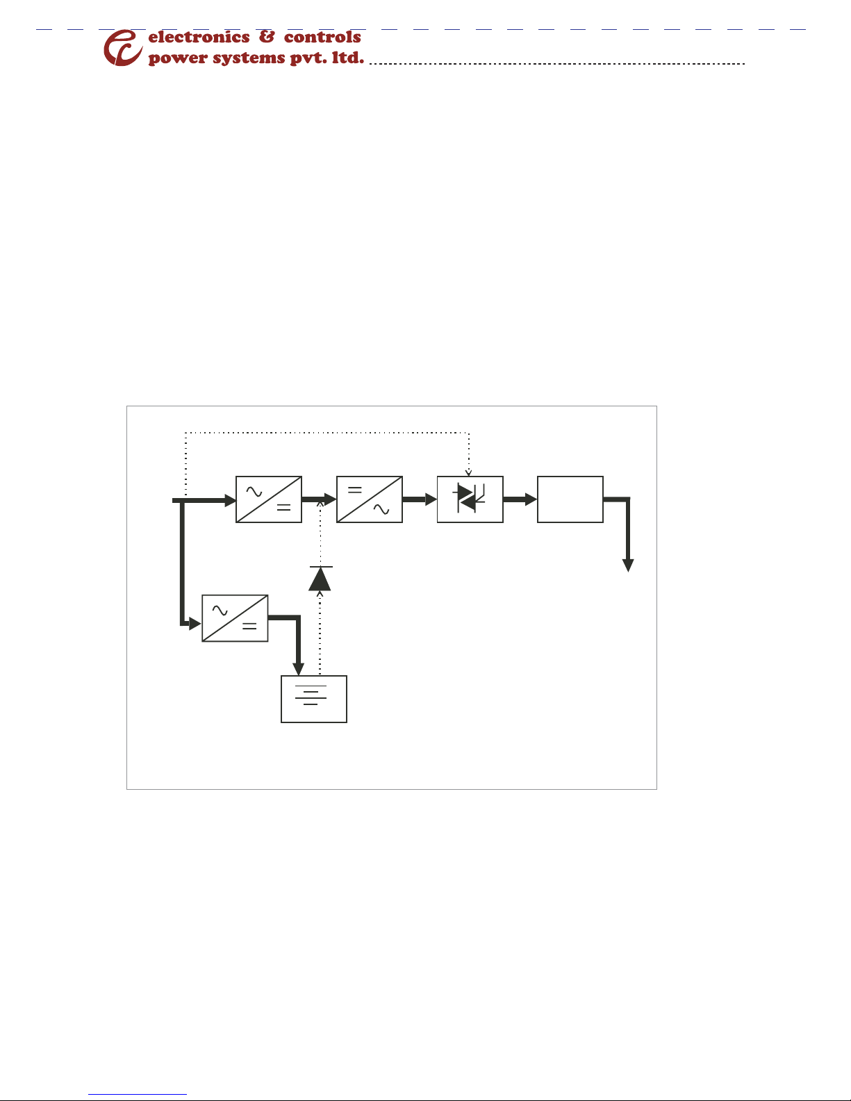
On-Line UPS can supply adjusted stable uninterruptible power to
electrical equipments. When AC fails, Voltage vary, voltage surge and
noise conditions, UPS can keep the load works normally. In common
operations, UPS first feed the power to rectifier for adjust and eliminate
the unstable factor, then through inverter transfer the DC to pure AC to
the Load. When UPS detect AC Voltage below the acceptable range of
load, UPS turn from AC to battery Mode. Under this condition, battery
power through inverter supply and supply stable power to Load. When
AC turns back to the acceptable range of Load, Ups automatically adjust
power again to the rectifier and inverter. Meanwhile, UPS charge the
Battery. During the full courses, it has no transfer time from AC to
battery backup, operating will not be interrupted, So we call it true on
line UPS.
Further more, when inverter stopped output if UPS fails, system
will automatically transfer to the bypass. AC supplies power directly to
load. All courses will not power off.
UPS can supply stable power to electrical machines and carry
with the following characters:
?Improve Power quality.
?Reduce the noise Disturb.
?Compatible with most loads.
?Output Protection when power off.
?Perfect battery protection.
Renata I - Series User Manual

Page 3
2. Theory of Operation
2.1. Modes of Operation
1. AC normal mode:
As shown in Fig 1.1, the AC power supply passes through rectifier / inverter /
static switch / filter to the output and chargers the battery by the charger.
Rectifier Inverter Static Switch Filter
EMI
Charger
Input
Output
Battery
Fig: 1.1
Renata I - Series User Manual

Page 4
Rectifier Inverter Static Switch Filter
Input EMI
Output
Charger
Battery
Fig: 1.1
3. Bypass Mode:
As Shown in Fig 1.3, the unit will switch to bypass mode under the following
conditions:
1. Over Load
2. Inverter Failure
3. The inverter switch on the front panel isn’t pushed to the “ON” or within the
initial 25 seconds after it is pushed to “ON”
4. The inverter switch is pushed to the “OFF”.
2. Power Failure Mode:
As shown in Fig 1.2, the battery supplies the output to Load through
the inverter.
Renata I - Series User Manual

Page 5
Rectifier Inverter Static Switch Filter
Input EMI
Output
Charger
Battery
Fig: 1.3
B. External Views
Renata I - Series User Manual

Page 6
3. Safety Instruction
3.1 (A). Preparation:
To achieve ultimate performance of this on-Line UPS, Please observe the
Following.
1. Read the User’s Manual.
2. Follow the Operating Instructions closely.
3. Be gentle and careful when moving the unit around.
4. Plug into the correct power source.
5. Never open the cabinet to avoid electric shock and damaging to the unit.
6. Do not apply load which is exceeds the rated capacity, Otherwise damage
may occur.
7. Keep the User’s manual handy for quick reference.
8. Refer the trouble shooting guide when having problems.
9. Keep the unit clean all time.
3.1. (B). System setup:
1. Precaution
1. Remove all the wires.
2. Handle the unit very carefully and avoid dropping.
3. Never leave the unit upside down.
3.2. Installation
Refer to the following Instructions for system install:
Input:
a. Never plug the unit into a wall outlet. The standard 15A wall outlet
will not support the heavy load of the unit.
b. It is safe to connect the unit to the nearest utility panel.
c. Refer Fig for terminal block connections. The input power should be
connect to the right terminals. Note also that UPS output and
external batteries also share the same terminal block.
d. Use high quality power wires.
Renata I - Series User Manual

Page 7
e. Always turn power off before wiring.
f. Please follow the standard wiring procedures.
g. Check for the correct Polarity.
h. Avoid sharing the same terminals with other equipments.
i. When wiring is done make sure that no wires touches the metal case
to prevent short circuit.
Renata I - Series User Manual
5kVA/192VDC/11 UPS TERMINAL CONNECTION DETAILS
7.5/10//15/20KVA/384VDC/31 UPS TERMINAL CONNECTION DETAILS

Page 8
3.3. Operating Instructions:
3.3.1. Pre-testing
To ensure proper functioning of the UPS, the following step should be
followed:
1) Double check the site of installation.
2) Make sure that the Power switch on the rear panel is OFF.
3) Unplug all loads.
4) Use a tester to check if the input voltage is at rated level.
5) Gently twist the input/output wiring and tighten loose ones.
6) Inspect the input/output fuses to be in working order.
3.3.2. Controls and LCD Indicators:
Renata I - Series User Manual
8
7
6
5
10
9

Page 9
1. Bypass On (Green).
2. Load on Bypass (Yellow).
3. Mains ON (Green).
4. Load On Battery (Yellow).
5. Load On Inverter (Green).
6. Output ON (Green).
7. Input fault (Red).
8. Battery Low (Red).
9. Inverter Fault (Red).
10. Over Load.(Red).
11-15. Battery Levels LED Indicators.
16 – 20 Load Levels LED Indicators.
21. Display.
Control Switches:
1. SW1 - Inverter OFF Switch (Red).
Turn OFF the Inverter, When press SW1(red) for 5 Sec, the unit will
turn off the inverter and unit transfer from normal operation to
Bypass mode.
2. SW2 - DPM Scroll (Blue).
3. SW3 - Inverter ON Switch (Green).
Turn ON the Inverter, When press SW3 (Green) , the unit will turn
ON the inverter and unit transfer from Bypass to Normal operation..
Power Switch
Located at the rear panel of the unit controls the input AC power and
Input batteries power for the unit.
3.3.3. Power ON Procedure:
The procedure is very simple. Please follow the steps for bellow operations.
Start Up.
a) Make sure that the power switch is OFF and there is no equipment
connected to the unit.
b) Check for correct input voltage.
c) Power ON the unit and the LINE, BYPASS, Load ON Bypass and Output
indicator will be ON. The cooling fans will also be running.
d) In about 20 seconds, the Bypass Indicator will be OFF while the Inverter will
be On indicating every thing is normal.
Renata I - Series User Manual


B. Troubleshooting Guide
A. “Mains ON” Indication not ON
Page 12
A
Is power
switch ON?
Turn ON
power switch
Is “Line”
Indication
ON?
Is the Input
Voltage
Normal?
Call for
Service
Continue
Yes
No
Yes
Check the AC
Input
No
No
Yes
Fig : IV-1
Renata I - Series User Manual

Page 13
B. Inverter Indication not ON
B
Is Inverter
switch is ON?
Turn ON
Inverter switch
Is “Inverter”
indication ON?
Did “Inverter”:
indicators go off
in 20 Sec?
Disconnect
the Loads
Continue
operation
Yes
No
Yes
No
Yes
No
Call for
Service
Did “Inverter”:
indicators go off
in 20 Sec?
Yes
Fig : IV-2
No
Renata I - Series User Manual

Page 14
C. Load on bypass Indication ON
C
Is Inverter
switch is ON?
Turn ON
Inverter switch
Is “Load on
Bypass” Indication ON
after 20 Sec
Continue
operation
Yes
No
No
Yes
Yes
No
Call for
Service
Is “Fault”
Indicators ON?
No
Fig : IV-3
Is the Input
Voltage
Normal?
Yes
D
Disconnect some
uncritical loads
No
Renata I - Series User Manual

Page 15
D. “INVERTER FAULT” Indication ON
D
Reconnect all
Loads and turn ON
No
Yes
Call for
Service
Is “Fault”
Indicators ON”
Yes
Fig : IV-4
No
Turn OFF the
“Inverter Switch”
Disconnect
Loads
Turn ON the
“Inverter Switch”
Is “Inverter”
indicators ON? B
Renata I - Series User Manual

Page 16
6. Technical Specifications
Renata I - Series User Manual

Page 17
Our Contact Information
Head Office
29/A, 2nd Phase, Peenya Industrial Area, Bangalore - 560 058, India.
Tel No : +91-80-28371974 / 28379401, Fax No : +91-80-28391587
For sales enquiries contact : sales@eandcpower.com
Regional Sales Offices
wAhmedabad wBangalore wChandigarh wChennai wCochin wHyderabad
wIndore wJaipur wKolkata wLucknow wMumbai wNew Delhi
Service Locations
•Agra
•Ahmedabad
•Aurangabad
•Agartala
•Bangalore
•Baroda
•Bhopal
•Bhubaneshwar
•Chandigarh
•Chennai
•Cochin
•Coimbatore
•Calicut
•Dehradun
•Guwahati
•Gwalior
•Hubli
•Hyderabad
•Indore
•Jabalpur
•Jaipur
•Jammu
•Kanpur
•Kolkata
•Kottayam
•Ludhiana
•Lucknow
•
•Madurai
Meerut
•Mumbai
•Munnar
•Mangalore
•Mysore
•Nagpur
•New Delhi
•Ongole
•Palakkad
•Patna
•Pondicherry
•Pune
•Raipur
•Ranchi
•Rajamundry
•Salem
•Srinagar
•Tirupati
•Trichy
•Tirunelveli
•Trivandrum
•Udaipur
•Vizag
•Vijayawada
•Varanasi
Works
A-95(BIS), PIPDIC Industrial Area, Mettupalayam, Pondicherry - 605 009,
India. Tel No : +91-413-2277241, Fax No : +91-413-4302241
For Service, Call our Helpline......... Tel No: 91-80-28397120 / 28397121
www.eandcpower.com
Renata I - Series User Manual
Table of contents