EarthCore ISOKERN ISOFLAME ISF24LB Owner's manual

2/2021 ISOFLAMES LINEAR BURNER
1
ISOFLAMES® Linear Burner
Installation, Operation, Maintenance and Owner’s Manual
Isokern Linear Burner Models:
ISF24LB - ISF36LB – ISF48LB
ISF60LB - ISF72LB - ISF96LB
A PRODUCT OF EARTHCORE® INDUSTRIES, LLC
Important: This manual contains assembly rules, installation steps, guidelines, use and maintenance instructions for the
Isoflames Linear Burner Series. This manual must become the property of and be reviewed by all current and future users of
this product. It is the responsibility of the general contractor and the installer of this product to ensure that the instructions
in this manual are followed exactly and be installed in strict accordance with the following sizing, installation, and operation
instructions. It is the responsibility of the general contractor to provide adequate clearances from all firebox surfaces as
specified in this manual.
Be Sure to Read Entire Manual Before Beginning Construction.
Contents of this manual may change without prior notification.
PFS Report No. F19-161
Issued: February 2021
Revision: 000
©2020 Earthcore Industries, LLC
THESE FIREPLACES ARE DESIGNED FOR USE WITH:
PROPANE (LP) OR NATURAL GAS (NG), ONLY
THIS MANUAL CAN ONLY BE REPRODUCED IN ITS ENTIRETY
INSTALLER: Leave this manual with the appliance
CONSUMER: Retain this manual for future reference
Design Certified to Z21.60 - Decorative Gas
Appliance for installation in solid-fuel burning
fireplace
The Isoflames Linear Burner is to be installed in solid-
fuel burning fireplace with a working flue and
constructed of noncombustible material. The
installation including provisions for combustion and
ventilation air must conform with the National Fuel
Gas Code, ANSI Z223.1/NFPA 54, or the CSA B149.1
Natural Gas and Propane Installation Code, and
applicable local building codes. chimney damper
must be fixed in a manner that will maintain the
minimum permanent vent opening at all times. A
damper clamp is supplied to maintain the minimum
permanent vent opening and prevent complete
closure of damper flap. Warning: Solid fuels shall not
be burned in a fireplace where a decorative
appliance is installed.

ISFOLAMES LINEAR BURNER 2/2021
2
Table of Contents
Table of Contents...................................................................................................................................................................................2
Isoflames Linear Burner - Safety Instructions........................................................................................................................................5
Isoflames Linear Burner - Components List ...........................................................................................................................................6
Isoflames Linear Burner - Specifications................................................................................................................................................7
Gas Line & Valve Box Installation...........................................................................................................................................................8
Burner Installation ...............................................................................................................................................................................10
Burner Installation ...............................................................................................................................................................................11
Burner Assembly Connection ..............................................................................................................................................................12
Burner Lighting Instructions ................................................................................................................................................................16
Remote Control System .......................................................................................................................................................................17
Troubleshooting...................................................................................................................................................................................19
Glass Media Options ............................................................................................................................................................................20
Optional Log Sets .................................................................................................................................................................................21

2/2021 ISOFLAMES LINEAR BURNER
3
Isoflames Linear Burner - Safety Instructions
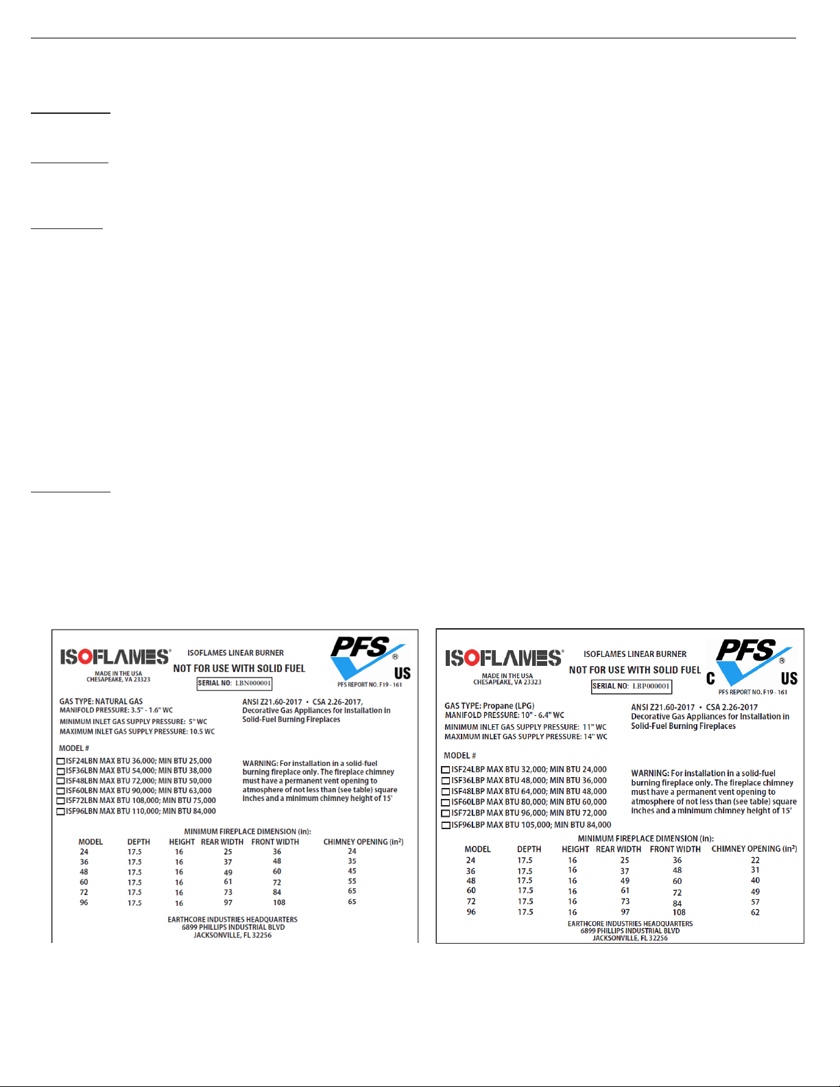
WARNING!!!: This appliance assembly contains burner orifices specifically for the input gas specified on the burner and
box, as well as the BTU rating specified in this manual. Modifying or failure to use the factory orifice may cause property
damage, personal injury, or loss of life
.
Read these instructions completely before installing and using ISOFLAMES Linear Burner
.
1)
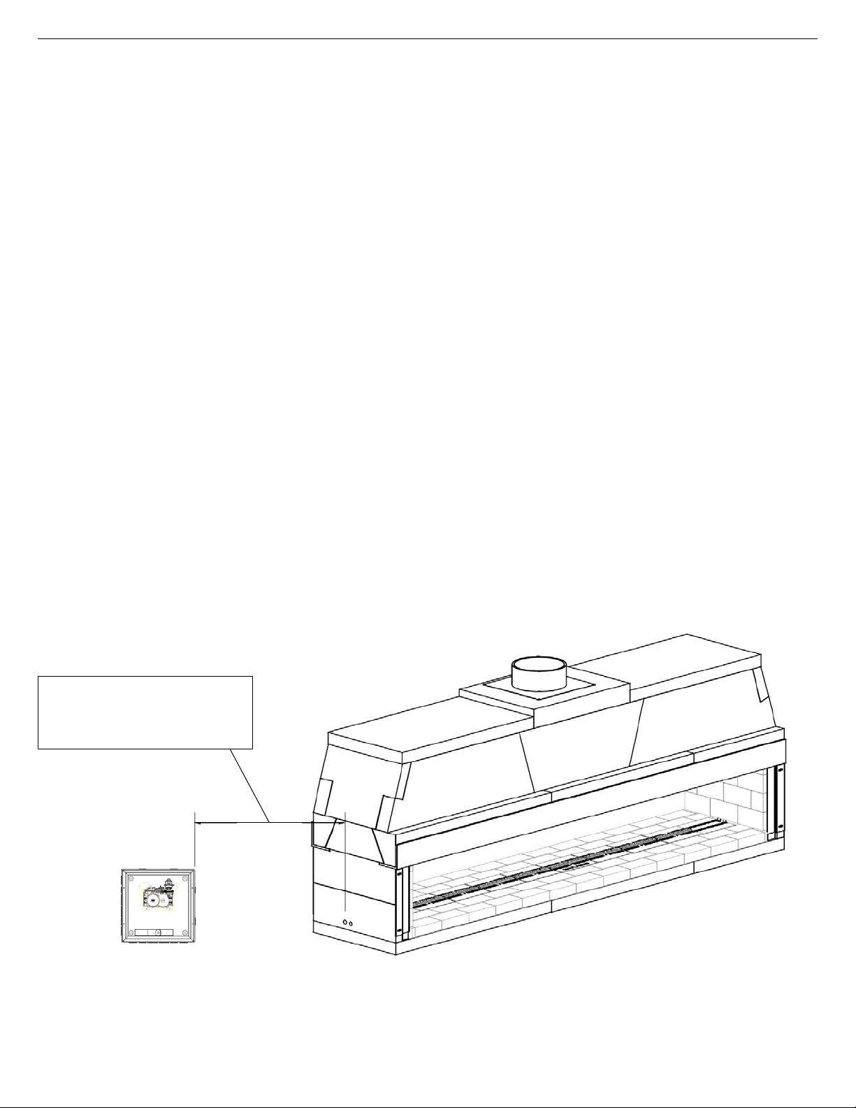
This Maximus Linear Series fireplaces must utilize the Isoflames Linear Burner that is specified for the particular fireplace
model.
2)
The Maximus Linear Series fireplaces utilize a mechanical draft system that interlocks with the Isoflames Linear burner to
ensure burner operation is only possible when the mechanical draft system is energized, and safe operation is proved by
the control. This ensures all carbon monoxide and other flue gases will be expelled through chimney system.
3)
Solid fuels shall not be burned in the Maximus Linear Series fireplaces, or any fireplace where a decorative appliance
has been installed.
4)
The minimum inlet supply pressure for the purpose of input adjustment is 5.0 inches (natural gas) 11.0 inches (propane)
in water column. The maximum inlet supply pressure is 10.5 inches (natural gas) 13.0 inches (propane) in water column.
5)
Gas type will be indicated on the burner rating plate. Do not use a natural gas burner with propane or a propane burner with
natural gas. Appliance is not convertible to use other gases.
6)
The installation, provisions for combustion, and ventilation air must conform to the National Fuel Gas Code, ANSI Z223.1/
NFPA 54, or the Natural Gas and Propane Installation code, CSA B149.1.
7)
The appliance and its main gas valve must be disconnected from the gas supply piping system during any pressure testing
of that system at test pressures in excess of 1/2 psi (3.5 kPa). The appliance must be isolated from the gas piping system
by closing its equipment shutoff valve during any pressure testing of the supply piping system at test pressures equal to
or less than 1/2 psi (3.5 kPa).
8)
Do not use this appliance if any part has been under water. Immediately call a qualified service technician to inspect the
appliance and to replace any part of the control system and any gas control which has been under water.
9)
Periodic examination and cleaning of the venting system of the solid fuel burning fireplace, including frequency of such
examination and cleaning, by a qualified agency.
10)
The appliance area is to be clear and free from combustible materials, gasoline and or flammable vapors and liquids. For
warranty to be valid gas log sets must be installed by a NFI certified or other qualified professional installer.
11)
Always check local building codes governing fireplaces and fireplace installations. ISOFLAMES Linear Burner installation
must comply with all local, regional, state, and national codes and regulations.
12)
This appliance is only for use with the type of gas indicated on the rating plate. This appliance SHALL NOT be field
converted for use with other gases with Propane (LP) or Natural Gas (NG).
13)
This appliance shall only be installed, serviced, or inspected by qualified professional service technician.
14)
For propane (LP) use do not place propane supply tank(s) inside any structure. Locate propane supply tank(s) outdoors.
15)
To prevent performance problems, do not use propane fuel tank of less than 100 lbs. capacity.
16)
This decorative gas appliance reaches high temperature. Keep children and adults away from hot surfaces to avoid burns or
clothing ignition. Fireplace will remain hot for a time after shutdown. Allow surfaces to cool before touching.
17)
Turn the appliance off and allow to cool before servicing. Always shut off any electricity and gas to the appliance while
working on it. Only a qualified service person should install, service or repair this appliance. Have your appliance
inspected annually by a qualified service person.

ISFOLAMES LINEAR BURNER 2/2021
4
Isoflames Linear Burner - Safety Instructions
18)
It is imperative that the unit’s control areas, burners and circulation air passages be kept clean.
19)
Keep all combustible material, gasoline, and other flammable liquids at a safe distance from the fireplace. Do not use
the appliance where these items are used or stored. Decorations, clothing, and other such combustible items should not
be placed on the appliance.
20)
Do not cook food or burn paper or other object(s).
21)
Do not use any solid fuels - wood, coal, paper, cardboard, etc. - Use only the gas type listed on the fireplace’s burner
rating plate.
22)
Do not in any way obstruct the flow of combustion and ventilation air. Provide adequate clearances around air openings
into the combustion chamber as well as adequate accessibility clearances for servicing and proper operation.
23)
Never install an ISOFLAMES Linear Burner component or accessory that has visible or suspected physical damage. These
items should be inspected by a qualified representative to ensure safe condition. When in doubt, consult your local
supplier.
24)
Do not alter or modify the ISOFLAMES Linear Burner or burner components under any circumstances. Modification or
alteration of any sort may void manufacturer’s warranty, listings, and approvals.
25)
The ISOFLAMES Linear Burner system is not intended to heat an entire home or to be used as a primary heat source.
26)
Children and adults should be alerted to the hazards of high surface temperature and should stay away from this appliance to
avoid burns or clothing ignition.
27)
Young children should be carefully supervised when they are in the same room as the appliance. Toddlers, young
children, and others may be susceptible to accidental contact burns. A physical barrier is recommended if there are at-
risk individuals in the house. To restrict access to the fireplace, install an adjustable safety gate to keep toddlers, young
children and other at-risk individuals out of the room and away from hot surfaces.
28)
Clothing or flammable material should not be placed on or near the appliance.
29)
Due to high temperatures, the appliance should be located out of traffic and away from furniture and draperies.
30)
Any safety screen, guard, or barrier removed for servicing an appliance must be replaced prior to operating the appliance.
31)
Installation and repair should be done by a qualified service person. The appliance should be inspected before use and
at least annually by a professional service person. More frequent cleaning may be required due to excessive lint from
carpeting, bedding material, etcetera. It is imperative that control compartments, burners, and circulating air
passageways of the appliance be kept clean.

2/2021 ISOFLAMES LINEAR BURNER
5
Isoflames Linear Burner - Safety Instructions
WARNING!!!: This product contains or generates chemicals known to the state of California to cause cancer or birth
defects or other reproductive harm.
I
MPORTANT: Read this owner’s manual carefully and completely before trying to assemble, operate or service this
fireplace. Improper use of this fireplace can cause serious injury or death from fire, burns, explosions and carbon
monoxide poisoning.
DANGER!!!: CARBON MONOXIDE POISONING MAY LEADTO DEATH!
Propane (LP) gas and natural gas (NG) are both colorless and odorless gases. An odor making agent is added to each of
these gases to help you detect a gas leak. However, the odor added to these gases can fade and gas may be present even
though no odor exists.
Carbon Monoxide Poisoning: Early signs of carbon monoxide poisoning resemble flu symptoms, including headaches, dizziness
or nausea. If you have these signs the fireplace may not have been installed properly, get fresh air at once! Have the fireplace
inspected and serviced by a qualified service person or your gas supplier. Some people are more affected by carbon monoxide
than others. These include pregnant women, people with heart or lung diseases or anemia, people at high altitude or under the
influence of alcohol. Earthcore Industries strongly recommends the use of a carbon monoxide detector/alarm device wherever
gas fired appliances are in use.
All parties either involved in or associated with the installation, service and use of this fireplace must read this entire manual.
Keep this manual for reference and as a guidebook to safe operation of this fireplace.
WARNING!!!: This unit is not for use with solid fuel.
Isoflames Linear Burner - Rating Plate
Natural Gas Label
L.P.G (propane) Label

ISFOLAMES LINEAR BURNER 2/2021
6
Isoflames Linear Burner - Components List
NOTE: model ISF
24
LB shown
③
Top view
⑤
⑥
Bottom view
⑦
⑧
Item No.
Description
Part
No.
Qty
1
Main Burner Assembly (natural gas)
Main Burner Assembly (propane)
ISF-E-36/60/72/96N
ISF-E-36/60/72/96P
1
1
2
Pilot Assembly (natural gas)
Pilot Assembly (propane)
ISF-E-PAN
ISF-E-PAP
1
1
3
Gas Valve (natural gas)
Gas Valve (propane)
ISF-E-GVN
ISF-E-GVP
1
1
4
Control module/remote receiver
ISF-E-CM
1
5
Battery Holder/Switch
ISF-E-BH
1
6
Remote Transmitter
ISF-E-RM
1
7
1/2" Flared fitting female adapter
ISF-E-FFA1
1
8
3/8" Flared fitting female adapter
ISF-E-FFA2
1
9
Damper Clamp
ISF-E-DC
1
10
12" Flex connector
ISF-E-FC12
1
11
Wall Plate Cover
E-EWC
1
⑩
⑪
④
①
TABLE 1

2/2021 ISOFLAMES LINEAR BURNER
7
Isoflames Linear Burner - Specifications
Burner Specifications
Burner Model
Minimum Fireplace Dimension (in)
BTU
Depth Height
Width
Nat. Gas
L.P. Gas
Front
Rear
High
Low
High
Low
ISF24LB
17.5
16
36
25
36K
25K
32K
24K
ISF36LB
17.5
16
48
37
54K
38K
48K
36K
ISF60LB
17.5
16
72
61
90K
63K
80K
60K
ISF72LB
17.5
16
84
73
108K
75K
96K
72K
ISF96LB
17.5
16
108
97
108K
84K
105K
87K
NOTE: Opening height is measured from hearth floor to bottom of lintel
TABLE 2
Note: Height is measured from hearth to top of chimney and minimum height is 15 ft.
TABLE 3

ISFOLAMES LINEAR BURNER 2/2021
8
Gas Line & Valve Box Installation
This appliance must be connected to the gas line in accordance with local codes and/or the National Fuel Gas Code, ANSI Z223.1.
After connecting the gas line, all joints in the line and connections at the valve should be checked for leaks before final positioning
of the unit. Conduct a gas leakage test of the appliance piping and control system downstream of the shutoff valve in the supply
line to the appliance.
1)
The valve control box comes with an 84” pilot assembly lead; therefore, the box must be mounted within 5’ of the fireplace for
models ISF24/36/48LB and within 1’ for models ISF72/96LB.
(Figure 1)
2)
Attach the metal enclosure to the studs using standard building materials. The metal enclosure must be mounted ina location
that can be accessed in the future for additional connections & future servicing.
3)
Installation and servicing of gas appliances and ignition systems must only be performed by qualified personnel.
4)
Turn off gas and electricity before starting installation or service.
5)
Make sure gas piping is pressure tested before control is connected. High pressure can damage the control causing a
hazardous condition.
6)
Make sure piping is clean and free from burrs. Apply a small amount of good quality gas-rated pipe thread compound or
plumbers’ tape suitable for the gas being used. Thread compound should be used sparingly on male threads only, leaving the
first two threads clean.
7)
It is recommended that a safety shut off valve is installed on either the gas in or gas outside of the valve.
8)
It is recommended to hard pipe in the connections with unions installed inside the box.
9)
Uncoil the pilot assembly. Be careful to not create unwanted kinks in the pilot tubing.
10)
Feed the spade connector ends of the pilot assembly from inside the fireplace to the outside being careful not to clog the
flared fitting of the pilot tube or damage the spade connectors.
11)
Plug the spade connectors into the module according to the below wiring diagram
(Figures 2 & 3)
, insert the pilot tubinginto
the right side of the valve and, using a wrench, tighten the nut so that the pilot tubing cannot be pulled out.
2
FIGURE 1
5’ FOR MODELS ISF24/36/48LB
OR
1’ FOR MODELS ISF72/96LB

2/2021 ISOFLAMES LINEAR BURNER
9
4
Valve Box & Burner Wiring Diagram
WARNING!!!: Do not connect 120 VAC to the control valve.
The appliance and its appliance main gas valve must be disconnected from the gas supply piping system during and
pressure testing of that system at test pressures in excess of 1/2 psi (3.5 kPa).
The appliance, when installed, must be electrically grounded in accordance with local codes or in the absence of local
codes, with the National Electrical Code, ANSI/NFPA 70. If not installed and maintained in accordance with the
manufacturer’s instructions, this product could expose you to substances in fuel or fuel combustion which are known to
the state of California to cause cancer, birth defects or other reproductive harm.
For a copy of the homeowner’s care and operation manual, go to www.earthcore.com or call 1-800-642-2920.
3
FIGURE 2
TABLE 4
FIGURE 3

ISFOLAMES LINEAR BURNER 2/2021
10
Burner Installation
IMPORTANT: Prior to installation: Shut off main gas supply to fireplace.
•
The ISOFLAMES Linear Burner system shall be installed by qualified professional service technician. To ensure proper
performance of the appliance the owner’s installation manual must be followed carefully.
•The ISOFLAMES Linear Burner is designed to be recessed into the 2 1/2” deep firebrick cavity constructed as detailed in Table 5
•The burner cavity must have a height of 2-1/2”, a depth of 9-1/4”, and the length shall extend the entire width of firebox.
•
If the gas supply pipe, from the external mounted valve, is brought into the cavity through the sidewall of the firebox, the
cavity must extend to the firebox sidewall
•For models ISF24/36/48/60LB: Gas supply shall terminate not less than 3” from sidewall. Figure 6
•For models ISF72/96LB: Gas supply shall terminate within than 4” from center of the cavity. Figure 6
BURNER CAVITY DIMENSIONS (in)
Burner Model
Height
Width
Length (Min)
ISF24LB
2-1/2
9-1/4
23
ISF36LB
2-1/2
9-1/4
35
ISF48LB
2-1/2
9-1/4
47
ISF60LB
2-1/2
9-1/4
59
ISF72LB
2-1/2
9-1/4
71
ISF96LB
2-1/2
9-1/4
95
TABLE 5
FIGURE 4
FIGURE 5
Note: make sure cavity length has enough space for gas supply line.

2/2021 ISOFLAMES LINEAR BURNER
11
Burner Installation
1.
Connect all burner segments according to burner model diagram Page 11 - 15. Make sure all connections are tightly
secured.
2.
Place burner assembly in center of fireplace floor/cavity.
3.
Rotate the burner to position the gas inlet flared fitting to be on same side as the gas-supply stub coming from the gas valve.
(Not necessary for models ISF72/96LB)
4.
Remove the burner top closest to the gas-supply stub. Remove the top pan by unscrewing the two screws. This
will allow easier access and connection of flex connector to the flared fitting. This will also be used for pilot
assembly installation.
5.
Ensure the appropriate 3/8” flared fitting is connected to the gas supply stub.
6.
Connect the 12” flex connector to the gas inlet flared fitting on the burner assembly.
7.
Connect the other end of 12” flex connector to the gas-supply.
8.
Avoid creating kinks in the flex connector.
9.
Make sure all connections are tightly secured.
10.
Before replacing the removed burner top from
step 4
, locate the perforated rectangular section in the pan. Gently
remove this section along the perforations using a screwdriver or pliers.
Figure 7
11.
Insert the pilot assembly from underneath the existing burner pan to the area of the removed burner section.
Figure 8
12.
Mount the pilot assembly to the removed burner pan using the screws provided with the pilot assembly. Be careful
not to kink the pilot assembly tube as it can severely damage the pilot tube.
Figure 9
13.
Place the removed burner top back on to the orifice block and secure tightly with the pan head screws.
14.
Check appliance operation. See Burner lighting instructions Page 16.
15.
Spread glass media evenly across burner. Do not fill cavity with glass media.
16.
Make sure glass media does not obstruct pilot assembly.
17.
Optional gas logs available, shown on page 20.
FIGURE 6
FIGURE 7
FIGURE 8
FIGURE 9

ISFOLAMES LINEAR BURNER 2/2021
12
Burner Assembly Connection
24” Burner Connection - ISF36LB
36” Burner Connection - ISF36LB
ISF36LB
Box No. Part No. Qty.
4 E-18BP4 1
8
E-12BP1
1
4
8

2/2021 ISOFLAMES LINEAR BURNER
13
48” Burner Connection – ISF48LB
60” Burner Connection – ISF60LB
ISF60LB
Box No.
Part No.
Qty.
1
E-18BP1
1
4
E-18BP4
1
6 E-18BP6 1
4
6
1

ISFOLAMES LINEAR BURNER 2/2021
14
72” Burner Connection – ISF72LB
ISF72LB
Box No.
Part No.
Qty.
4
E-18BP4
1
5
E-18BP5
1
9 E-12BP2 1
10 E-12BP3 1
13 E-BPC 1
5
10
13
9
4

2/2021 ISOFLAMES LINEAR BURNER
15
96” Burner Connection – ISF96LB
ISF96LB
Box No.
Part No.
Qty.
2 E-18BP2 1
3
E-18BP3
1
9 E-12BP2 1
10 E-12BP3 1
11 E-12BP4 1
12 E-12BP5 1
13 E-BPC 1
13
3
10
12
9
2
11

ISFOLAMES LINEAR BURNER 2/2021
16
Burner Lighting Instructions
INSTALLER INSTRUCTIONS
It is required that the set of safety instruction labels that have been supplied with the appliance be affixed to the
operation and control points of the appliance. It is the installers responsibility to ensure these warnings are properly
affixed during installation. These warning labels are a critical step in informing consumers of safe operation of this
appliance
.
PRE-LIGHTING CHECKLIST
Be sure to check these items before the initial lighting of the appliance:
•
Gas pressure has been checked carefully
•
All gas fittings have been checked for leaks.
•
All clearances to combustibles have been met
•
All combustibles materials have been removed from the area in front of the appliance.
•
All vented areas of the appliance face are unobstructed.
•House is ventilated to clear initial paint curing odors
•
All packaging materials have been removed from the appliance.
•
While appliance is cool, fingerprints or other marks have been cleaned from any plated surfaces with denatured
alcohol and a soft cloth. Marks left on these surfaces may become permanent into the finish if not removed prior
burning the unit.
WARNING!!!: IF YOU DO NOT FOLLOW THESE INSTRUCTIONS EXACTLY, A FIRE OR EXPLOSION MAY
RESULT CAUSING PROPERTY DAMAGE, PERSONAL INJURY OR LOSS OF LIFE.
SAFETY INSTRUCTIONS
A. This appliance is equipped with an ignition device which automatically lights the pilot. Do NOT try to light the pilot by
hand.
B.
BEFORE OPERATING smell all around the appliance area for gas. Be sure to smell next to the floor because some
gas is heavier than air and will settle on the floor.
WHAT TO DO IFYOU SMELL GAS
:
•
Do not try to light any appliance.
•
Do not touch any electric switch; do not use any phone in your building.
•
Immediately call your gas supplier from a neighbor’s phone. Follow the gas supplier’s instructions.
•
If you cannot reach your gas supplier, call the fire department.
C.
If any portion of this appliance does not operate as the instructions indicate, do not try to repair it, call a qualified
service technician. Do not use tools. Force or attempted repair may result in a fire or explosion.
D.
Do not use this appliance if any part has been under water.
Immediately call a qualified service technician to
inspect the appliance and to replace any part of the system and any gas control which has been under water.
OPERATING INSTRUCTIONS
Terminal X4 on module serves as Main Power switch. When X4 is jumpered, the Battery Holder Wall Switch functions
as a burner and pilot override switch. When in the
OFF
position, it will not let the burner or pilot be turned on by the
remote. When in the
ON
position the pilot and burner will initialize immediately. When in the
REMOTE
position, it
gives the remote full control over burner and pilot functions.
NOTE:
See Remote Control System on pages 15-16 for remote specific operating instructions.
TO TURN OFF GAS TO APPLIANCE
1)
Turn the burner ON/OFF switch to “OFF.”
2)
Turn off all electric power to the appliance if service is to be performed.
3)
Close the main line gas shut-off valve.
WARNING!!!: OPERATION OF THIS APPLIANCE WHEN NOT CONNECTED TO A PROPERLY INSTALLED AND
MAINTAINED VENTING SYSTEM CAN RESULT IN CARBON MONOXIDE (CO) POISONING AND POSSIBLE
DEATH.

2/2021 ISOFLAMES LINEAR BURNER
17
Remote Control System
The Remote allows you to command the functions of your appliance from the comfort of your chair and is
configured to control the On/Off primary burner operation, its flame height through six (6) levels, and
provides On/Off control of the appliance.
INSTALL THE REMOTE CONTROL SYSTEM
Required Items (not provided):
1)
Standard Junction Box
2)
Paper Clip or similar object (for remote control system initialization)
The receiver for the remote-control system connects directly to the gas valve, stepper motor, and fan control
module with an umbilical cord wiring harness.
1)
Install a junction box (not provided) on the wall adjacent to the appliance, within reach of the remote
system umbilical cord wiring harness.
2)
Position the terminal within the junction box in preparation for attachment to the remote wall switch.
3)
When wall finish is complete, install the wall switch in the previously installed junction box, and connect
the terminal to the connector on the back of the wall switch.
4)
Install the wall switch cover plate, taking care to ensure the wall switch is properly indexed with the switch
cover when aligning the components for attachments.
INITIALIZING THE SYSTEM FOR THE FIRST TIME
1)
Insert the three (3) provided AAA batteries into the battery bay in the transmitter. Correctly align polarity (+/–).
2)
Insert the four (4) provided AA batteries into the wall switch battery bay (behind the wall switch plate).
Correctly align polarity (+/–).
3)
On the wall switch, place the three-position slider switch in the REMOTE position.
4)
On the wall switch front cover, insert the end of a paper clip (or other similar object) into the hole marked
PRG.
NOTE:
The Receiver will beep three (3) times to indicate it is ready to synchronize with the transmitter.
5)
On the transmitter, press the ON button. The receiver will beep four (4) times to indicate acceptance of the
transmitter’s command (and set the receiver to the transmitter’s specific code). The system is now initialized.
LOW BATTERY POWER DETECTION
The life span of the Receiver batteries depends on various factors: quality of the batteries used, the number of
ignitions of the appliance, the number of changes to the room thermostat set point, etc.
When the Receiver batteries are low, two “beeps” will be emitted from the Receiver when it receives an ON/OFF
command from the Remote.
This is an alert for a low battery condition for the Receiver. When the batteries are replaced the “beep” will be
emitted from the Receiver when the ON/OFF key is pressed (See Initializing The System).
WARNING!!!:
Fire hazard. Can cause severe injury or death. The receiver causes ignition of the appliance. The
appliance can turn on suddenly. Keep away from the appliance burner when operating the remote system or
activating manual bypass of the remote system.
WARNING!!!:
Property damage hazard. Excessive heat can cause property damage. The appliance can stay lit for
many hours. Turn off the appliance if it is not going to be attended for any length of time. Always place the
Transmitter where children cannot reach it.

ISFOLAMES LINEAR BURNER 2/2021
18
Remote Control System
TEMPERATURE INDICATOR DISPLAY
With the system in the “OFF” position, press the Thermostat Key and the Mode
Key at the same time
(Figure 10).
Look at the LCD screen on the Remote to verify
that a C or F is visible to the right of the Room Temperature display
(Figure 11).
TURN ON THE APPLIANCE
Press the ON/OFF Key on the Remote. The Remote display will show all active
Icons on the screen and the appliance main burner will turn on
(Figure 11).
A
single “beep” from the Receiver will confirm reception of the command.
TURN OFF THE APPLIANCE
Press the ON/OFF Key on the Remote. The Remote LCD display will only show
the room temperature and Icon and the appliance burner will turn off. A single
“beep” from the Receiver confirms reception of the command.
REMOTE FLAME CONTROL
The system has six (6) flame levels. See (
Figure 11)
for an example. With the
system on, and the flame level at the maximum in the appliance, pressing the
Down Arrow Key once will reduce the flame height by one step until the flame is
turned off. The Up-Arrow Key will increase the flame height each time it is
pressed. If the Up Arrow Key is pressed while the system is on, but the flame is
off, the flame will come on in the high position
(Figure 12).
A single “beep” will
confirm reception of the command.
FLAME COLOR AND BEHAVIOR
This appliance is designed for maximum heating efficiency. Therefore, upon
lighting of the main burner, the flames will be semi-transparent or “bluish.”
After 10- 20 minutes of operation the logs will heat up and the flames will
become a yellow/ orange color.
Adjusting the appliance to cause the flames to turn orange sooner may result in
poor combustion, sooting and a hazardous situation. See (
Figure 13)
showing
proper flame appearance.
When testing for proper operation - If an optional thermostat is installed adjust
it to its highest temperature setting.Visually determine that main burner gas is
burning properly: i.e., no floating, lifting or flashback. Adjust the primary air
shutter(s) as required. Check for proper main burner operation at both high and
low flame.
FIGURE 10
FIGURE 12
FIGURE 13
FIGURE 11

2/2021 ISOFLAMES LINEAR BURNER
19
Troubleshooting
Earthcore Industries Technical Support: 1-800-642-2920
Issue
Probable
Cause
Possible Solution
No spark on pilot
No power
-
Verify power is ON
- Check wiring on ignition module and gas valve are
correct
Ignitor misalignment
Verify ignitor not contacting pilot gas hood
Loose pilot connections
- Check pilot wiring assembly is tightly secured to
ignition module
Pilot won't ignite
No spark
- See "No spark on pilot"
Air in pilot gas line
-
It may take a few minutes to purge out all the air from
the pilot gas tube to ignite
No gas
-
Verify pilot gas tube is threaded sufficiently to gas
valve
- Verify all gas connections going to and from gas
valve are tight
- Verify main gas-shutoff valve is in ON position
Pilot won't stay ignited
Flame sensor obstruction
Remove any obstruction near pilot igniter and flame
sensor
Loose pilot connections - Check pilot wiring assembly is tightly secured to
ignition module
Low gas pressure
- Verify adequate gas supply pressure
Remote won't
work/unresponsive
Range
- Remote is too far from receiver
Batteries need replacement
- Replace batteries on remote transmitter
Battery holder is "OFF"
- Slide the battery holder position to "REMOTE"
position
Program remote to receiver
-
Sync remote transmitter to ignition module; Page 15
Main burner won’t ignite
Pilot won’t ignite
- See "Pilot won't ignite"
Pilot flame won’t stay ignited
- See "Pilot won't stay ignited"
Loose burner segments
- Verify burner segments are tight and secure
Orifice blockage
Remove burner top pan tray and visually inspect orifice
gas block
Defective valve/ignition module - Replace gas valve or ignition module

ISFOLAMES LINEAR BURNER 2/2021
20
Glass Media Options
Component
Part#
Description
RFG-10-PB
1/2” REFLECTIVE POSEIDON
BLUE FIRE GLASS (10 LB JAR)
RFG-10-TC
1/2” REFLECTIVE TERRA
COPPER FIRE GLASS (10 LB
JAR)
RFG-10-VB
1/2” REFLECTIVE VESPER
BLACK FIRE GLASS (10 LB
JAR)
RFG-10-KD
1/2” REFLECTIVE KRYSTALLO
DIAMOND FIRE GLASS (10 LB JAR)
RFG-10-AD
1/2” REFLECTIVE AMBER
DIAMOND FIRE GLASS (10 LB
JAR)
Glass Media will be included with the Isoflames Linear Burner for each Maximus Linear Unit. A color selection will
need to be chosen when ordering your fireplace unit. The following designated amount will be included for each
size.
•
82L48 - 3 (10lb) Jars
•
82L72 - 5 (10lb) Jars
•
82L96 - 7 (10lb) Jars
•
82L120 - 9 (10lb) Jars
This manual suits for next models
5
Table of contents
Other EarthCore Burner manuals
Popular Burner manuals by other brands

Alva
Alva CCR101 manual

Ferroli
Ferroli SUN G3 Operating, installation and maintenance instructions

Eclipse Combustion
Eclipse Combustion RatioMatic RM Series Design guide

Mustang
Mustang 233282 manual

Finterm
Finterm OIL 4 PR instruction manual

Bentone
Bentone STG 120/2 Installation and maintenance instruction

Eno
Eno ATOLL Instructions for use

BRAND-MAN
BRAND-MAN BG2211A3 owner's manual

Riello
Riello DB 6 SM CO1 A0 Installation, use and maintenance instructions

John Lewis
John Lewis 85330112 Pre-assembly preparation

Roca
Roca TECNO 190-L Installation, use and maintenance instructions

Ariterm
Ariterm BioCompPX PX52 Installation and user instructions