EarthPeople Technology UnoProLogic User manual

User Manual EPT USB PLD Dev System
Page 1
UNOPROLOGIC
USB CPLD DEVELOPMENT SYSTEM
Data Sheet
The UnoProLogic is a part of the EPT USB/PLD development system. It provides an innovative
method of developing and debugging the users microcontroller code. It can also provide a high
speed data transfer mechanism between microcontroller and Host PC.
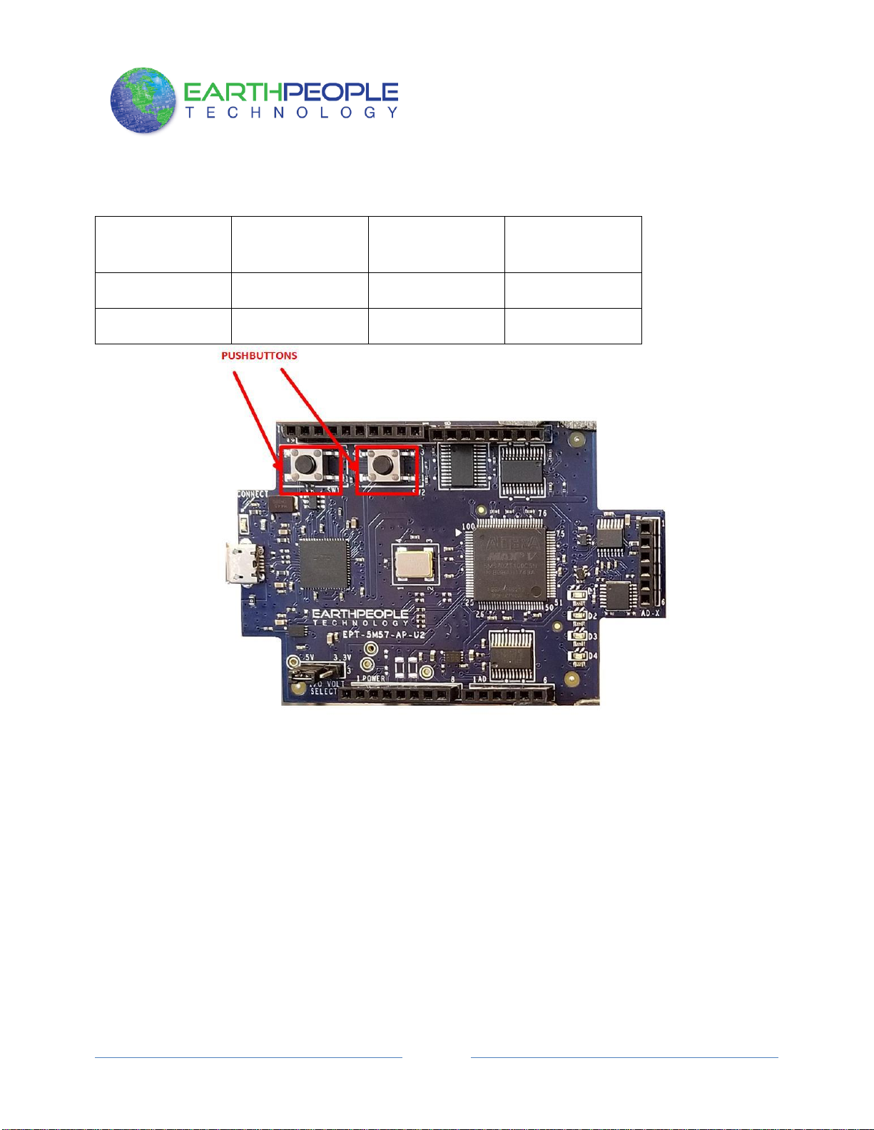
The UnoProLogic board is equipped with an Altera 5M570 PLD; which is programmed using the
Altera Quartus II software. The PLD has 570 Logic Elements which is equivalent to 440
Macrocells. An on board 66 MHz oscillator is used by the EPT-Active-Transfer-Library to
provide data transfer rates of 0.1 Mega Bytes per second. The EPT-Active-Transfer-Library
provides control communication between the objective device and the PLD. Data transfer during
the objective device checkout between the PC and the PLD program is available via the Hyper
Serial Port. The board also includes the following parts.

User Manual EPT USB PLD Dev System
Page 2
•Altera EPM570 in the TQFP 100 pin package
•66 MHz oscillator for driving USB data transfers and users code
•Four 74LVC245 bidirectional voltage translator/bus transceiver
•24 user Input/Outputs
•Four Green LED’s accessible by the user
•Two PCB switches accessible by the user
•All connectors to stack into the Arduino Uno
•USB to Serial FT2232H Dual Channel Chip.
1Block Diagram
Figure 1 UNOPROLOGIC Block Diagram

User Manual EPT USB PLD Dev System
Page 3
Figure 2 UnoProLogic Component Callouts

User Manual EPT USB PLD Dev System
Page 4
2Mechanical Dimensions
3Pin Mapping
Pin Mapping between Connectors, MAXV CPLD and User code
Component
Pin
Net Name
Pin on CPLD
Signal in EPT
Project Pinout
66MHz Oscillator
3
GCLK
12
CLK_66MHZ
Reset
2
NA
44
RST

User Manual EPT USB PLD Dev System
Page 5
U12
16
AD0
24
JTAG_TCK (Not
In Project)
17
AD1
23
JTAG_TDI (Not
In Project)
18
AD2
25
JTAG_TDO (Not
In Project)
19
AD3
22
JTAG_TMS (Not
In Project)
38
BD0
19
BD_INOUT0
39
BD1
18
BD_INOUT1
40
BD2
17
BD_INOUT2
41
BD3
16
BD_INOUT3
43
BD4
15
BD_INOUT4
44
BD5
14
BD_INOUT5
45
BD6
7
BD_INOUT6
46
BD7
6
BD_INOUT7
48
BC0
5
BC_IN1
52
BC1
4
BC_IN0
53
BC2
3
BC_OUT2
54
BC3
2
BC_OUT1
55
BC4
1
BC_OUT0
SW1
1
SW_USER_1
20
SW_USER_1
SW2
1
SW_USER_2
21
SW_USER_23
U7
2
TR_DIR_1
100
TR_DIR_1

User Manual EPT USB PLD Dev System
Page 6
U4
2
TR_DIR_2
29
TR_DIR_2
U5
2
TR_DIR_3
85
TR_DIR_3
U7
22
TR_OE_1
86
TR_OE_1
U4
22
TR_OE_2
28
TR_OE_2
U5
22
TR_OE_3
74
TR_OE_3
D1
1
LED_GR_1_N
54
LED0
D2
1
LED_GR_2_N
53
LED1
D3
1
LED_GR_3_N
52
LED2
D4
1
LED_GR_4_N
51
LED3
U9
16
ADC_EOC
67
ADC_EOC
12
ADC_CS
68
ADC_CS
13
ADC_SCLK
69
ADC_CLK
14
ADC_DIN
70
ADC_MOSI
15
ADC_DOUT
71
ADC_MISO
8
ADC_CNVST
72
ADC_CNVST
U7
21
LB0
87
LB_IOH0
20
LB1
89
LB_IOH1
19
LB2
91
LB_IOH2
18
LB3
92
LB_IOH3
17
LB4
96
LB_IOH4
16
LB5
97
LB_IOH5
15
LB6
98
LB_IOH6

User Manual EPT USB PLD Dev System
Page 7
14
LB7
99
LB_IOH7
U4
21
LB8
42
LB_SER0
20
LB9
41
LB_AD0
19
LB10
40
LB_AD1
18
LB11
38
LB_AD2
17
LB12
36
LB_AD3
16
LB13
35
LB_AD4
15
LB14
34
LB_AD5
14
LB15
33
LB_SER1
U5
21
LB16
81
LB_IOL0
20
LB17
82
LB_IOL1
19
LB18
83
LB_IOL2
18
LB19
84
LB_IOL3
17
LB20
78
LB_IOL4
16
LB21
77
LB_IOL5
15
LB22
76
LB_IOL6
14
LB23
75
LB_IOL7
4Pushbutton switches
There are two pushbutton switches on the UnoProLogic. Both are momentary contact switches.
They include a 1uF cap to ground to debounce both switches.

User Manual EPT USB PLD Dev System
Page 8
Component
Net Name
Pin on CPLD
Signal in EPT
Project Pinout
SW1
SW_USER_1
20
SW_USER_1
SW2
SW_USER_2
21
SW_USER_23

User Manual EPT USB PLD Dev System
Page 9
5LEDs
The UnoProLogic includes four Green LEDs. The LEDs are connected to the CPLD in a
“Current Sink”configuration. This means the LEDs Anodes are permanently connected to
+3.3V. Each Cathode side of the LEDs are connected to an individual I/O of the CPLD. In order
to turn on the LED, the CPLD I/O must apply a low signal. This will complete the LED drive
circuit and current will flow through the LED. To turn the LED off, the CPLD I/O must either
“float”or drive a high onto the pin.
Component
Net Name
Pin on CPLD
Signal in EPT Project
Pinout
LED1
LED[1]
50
LED[0]
LED2
LED[2]
51
LED[1]
LED3
LED[3]
52
LED[2]
LED4
LED[4]
53
LED[3]

User Manual EPT USB PLD Dev System
Page
10
6Host PC Connection
The UnoProLogic includes an LED that signifies the connection of the board with the Host PC.
The connect LED has the word “CONNECT”in silkscreen next to the LED. This LED will only

User Manual EPT USB PLD Dev System
Page
11
light up once the Host PC has correctly enumerated the USB device (FT2232HQ chip). When
this LED is lit up it can tell the user three things:
•Power has been applied to the UnoProLogic via USB
•The FT2232HQ chip is working properly
•The Host PC has found the appropriate driver and will communicate with the
UnoProLogic
7Inputs/Outputs
The UnoMax is designed from the ground up as a development board for beginners. All of the
Inputs/Outputs are protected by the 74LVC8245 transceiver chips. These transceivers provide
both voltage level translations and protection from over current and over voltage. The
transceivers can sink up to 50mA per pin.
There are 24 Inputs/Outputs which are selectable between +3.3V and +5 Volt. JMP1 is used to
select which voltage the 24 Inputs/Outputs are set to.

User Manual EPT USB PLD Dev System
Page
12
The
I/O’s are organized as three 8 bit directional ports. Each port must be defined as input or output.
This means that all 8 bits of a port will point in the same direction, depending on the direction bit
of the transceiver. The direction bit can be changed at any time, so that a port can change from
input to output in minimum setup time of 6 nanoseconds. Each port also has an enable pin. This
enable pin will enable or disable the bits of the port. If the port is disabled, the bits will “float”.

User Manual EPT USB PLD Dev System
Page
13
This 8-bit (octal) noninverting bus transceiver contains two separate supply rails; B port has
VCCB, which is set at 3.3 V, and A port has VCCA, which is set at 5 V. This allows for
translation from a 3.3-V to a 5-V environment, and vice versa.
The SN74LVC4245A device is designed for asynchronous communication between data buses.
The device transmits data from the A bus to the B bus or from the B bus to the A bus, depending
on the logic level at the direction-control (DIR) input. The output-enable (OE) input can be used
to disable the device so the buses are effectively isolated. The control circuitry (DIR, OE) is
powered by VCCA.
7.1 Electrical Characteristics
Tim

User Manual EPT USB PLD Dev System
Page
14
7.2 Timing Characteristics
7.3 Description
24 mA drive at 3-V supply
–Good for heavier loads and longer traces
Low VIH
–Allows 3.3-V to 5-V translation

User Manual EPT USB PLD Dev System
Page
15
8Analog connector
The UnoMax includes a six pin analog input connector. This connector provides a path from the
pins to the input of the four Op-Amp buffers. Each Op-Amp includes a 1MHz low pass filter.
Each Op-Amp provides a buffer for the analog signals to the ADC inputs.

User Manual EPT USB PLD Dev System
Page
16
9Analog to Digital Converter
The EPT 5M57-AP-U2 has an onboard Four Channel, 10 Bit, 300 KSamples/second Analog to
Digital Converter. It has a serial SPI communications that allow the host to send setup
commands and retrieve the sampled data.
PIN
NAME
FUNCTION
1–4
AIN0–AIN3
Analog Inputs

User Manual EPT USB PLD Dev System
Page
17
5, 6, 7
N.C.
No Connection
8
CONVST
Active –low Conversion Start
Input
9
REF
Reference Input
10
GND
Ground
11
VDD
Power Input
12
CS
Active Low Chip Select Input.
When CS is Low the interface
is enabled. When CS is high
MOSI is high impedance
13
SCLK
Serial Clock input. Clocks data
in and out of the serial
interface.
14
MISO
Serial Data input. MISO data
is latched into the interface
on the rising edge of SCLK
15
MOSI
Serial Data Output. Data is
clocked out on the falling
edge of SCLK. High
impedance when CS is
connected to VDD.
16
EOC
End of Conversion Output.
Data is valide after EOC pulls
low.

User Manual EPT USB PLD Dev System
Page
18
9.1 Electrical Characteristics
9.2 3-Wire Serial Interface
The MAX11618–MAX11621/MAX11624/MAX11625 feature a serial interface compatible with
SPI/QSPI and MICROWIRE devices. For SPI/QSPI, ensure the CPU serial interface runs in
master mode so it generates the serial clock signal. Select the SCLK frequency of 10MHz or less,
and set clock polarity (CPOL) and phase

User Manual EPT USB PLD Dev System
Page
19
(CPHA) in the μP control registers to the same value. The MAX11618 operate with SCLK idling
high or low, and thus operate with CPOL = CPHA = 0 or CPOL = CPHA = 1. Set CS low to
latch input data at DIN on the rising edge of SCLK. Output data at DOUT is updated on the
falling edge of SCLK. Results are output in binary format.
Serial communication always begins with an 8-bit input data byte (MSB first) loaded from DIN.
A high-to-low transition on CS initiates the data input operation. The input data byte and the
subsequent data bytes are clocked from DIN into the serial interface on the rising edge of SCLK.
Tables 1–5 detail the register descriptions.
Bits 5 and 4, CKSEL1 and CKSEL0, respectively, control the clock modes in the setup register.
Choose between four different clock modes for various ways to start a conversion and determine
whether the acquisitions are internally or externally timed. Select clock mode 00 to configure
CNVST/AIN_ to act as a conversion start and use it to request the programmed, internally timed
conversions without tying up the serial bus. In clock mode 01, use CNVST to request
conversions one channel at a time, controlling the sampling speed without tying up the serial bus.
Request and start internally timed conversions through the serial interface by writing to the
conversion register in the default clock mode 10. Use clock mode 11 with SCLK up to 4.8MHz
for externally timed acquisitions to achieve sampling rates up to 300ksps. Clock mode 11
disables scanning and averaging.
The device feature an active-low, end-of-conversion output. EOC goes low when the ADC
completes the last requested operation and is waiting for the next input data byte (for clock
modes 00 and 10). In clock mode 01, EOC goes low after the ADC completes each requested
operation. EOC goes high when CS or CNVST goes low. EOC is always high in clock mode 11.
9.3 Output Data Format
Figures 4–7 illustrate the conversion timing for the MAX11618–
MAX11621/MAX11624/MAX11625. The 10-bit conversion result is output in MSB-first format
with four leading zeros followed by 10-bit data and two trailing zeros. DIN data is latched into
the serial interface on the rising edge of SCLK. Data on DOUT transitions on the falling edge of
SCLK. Conversions in clock modes 00 and 01 are initiated by CNVST. Conversions in clock
modes 10 and 11 are initiated by writing an input data byte to the conversion register. Data
output is binary.

User Manual EPT USB PLD Dev System
Page
20
Table of contents
Popular Motherboard manuals by other brands

Supero
Supero P8SGA user manual

Texas Instruments
Texas Instruments INA185EVM user guide

Advantech
Advantech PCM-5825 user manual

Texas Instruments
Texas Instruments TMP461EVM User's Guide and Software Tutorial

VIA Technologies
VIA Technologies EPIA-EX15000G - VIA Motherboard - Mini ITX operating guide

Ublox
Ublox SARA-N3 series user guide