Easyguard EC002 Series User manual

User Manual of EC002
V2.1
Zhongshan Easyguard Electronics Co.,ltd
Add: 2nd floor, building 3, No 77 caihong Road, West district,
Zhongshan city, Guangdong, China
Phone: 86-760-22113597
Web: www.ieasyguard.com
Email: sales@ieasyguard.com
Important: This device can improve the vehicle safety level, but could not prevent the vehicle from
stolen or the occurrence of unexpected accidents. EASYGUARD Electronics will not be liable for any
resulting from the damage of this product cause by direct or indirect losses.
▶Contact us

INDEX
1.Push button start/stop -------------------------------------------------------------------------------------------------------33-34
2.PKE-passive keyless entry -----------------------------------------------------------------------------------------------------34
3.Manual arm/lock-------------------------------------------------------------------------------------------------------------------34
4.Manual disarm/unlock -----------------------------------------------------------------------------------------------------------34
5.Mute alarm & audible alarm ----------------------------------------------------------------------------------------------------34
6.Remote trunk release-------------------------------------------------------------------------------------------------------------34
7.Panic mode/Car finding----------------------------------------------------------------------------------------------------------34
8.To enable or disable PKE feature(PKE on/off setting)-------------------------------------------------------------------35
9.Remote engine start/stop---------------------------------------------------------------------------------------------------35-36
10.Dome light supervision (optional) -------------------------------------------------------------------------------------------36
11.Anti-hijacking ---------------------------------------------------------------------------------------------------------------------37
12.Alarm trigger by illegal door opening ---------------------------------------------------------------------------------------37
13.Central door locking automation --------------------------------------------------------------------------------------------37
14.Touch password entry -----------------------------------------------------------------------------------------------------37-40
15.Power off memory --------------------------------------------------------------------------------------------------------------40
16.Door unlock well warning -----------------------------------------------------------------------------------------------------40
17.Alarm reminder ------------------------------------------------------------------------------------------------------------------40
18.Door opening while driving warning ----------------------------------------------------------------------------------------40
19.ACC ON warning ----------------------------------------------------------------------------------------------------------------40
20.Emergency override ------------------------------------------------------------------------------------------------------------40
21.Power saving & car battery low power protection ----------------------------------------------------------------------40
22.Automatic window closing (optional) ---------------------------------------------------------------------------------------40
23.Vibration alarm (optional) -----------------------------------------------------------------------------------------------------41
24.GPS tracker (optional) ---------------------------------------------------------------------------------------------------------41
25.Parameter time prolong setting -----------------------------------------------------------------------------------------41-42
Technical parameter ----------------------------------------------------------------------------------------------------------------42
FAQS of EC002 -----------------------------------------------------------------------------------------------------------------43-44
Function description
Installation guide
Safety warning -------------------------------------------------------------------------------------------------------------------------1
1.Before starting the installation ------------------------------------------------------------------------------------------------2-3
2.DIP switch setting on control module ------------------------------------------------------------------------------------------3
3.Deciding on components locations --------------------------------------------------------------------------------------------4
Antenna & touch password keypad introduction ---------------------------------------------------------------------------4-8
Main wire harness introduction & note 1-18 -------------------------------------------------------------------------------8-14
Engine start button introduction ---------------------------------------------------------------------------------------------14-17
Key FOB buttons introduction & function description ------------------------------------------------------------------17-19
Manual for releasing the steering lock -------------------------------------------------------------------------------------20-21
Installation for chip immobilizer ----------------------------------------------------------------------------------------------21-22
Programming method --------------------------------------------------------------------------------------------------------------22
Central door locking wire connection---------------------------------------------------------------------------------------23-30
Wiring diagram of Easyguard EC002 --------------------------------------------------------------------------------------31-32

Dear Customer,
Thank you for purchasing our EASYGUARD EC002 series PKE car alarm with push start stop button. This
alarm is combine with latest PKE (passive keyless entry) technology, remote engine start, keyless go and
touch password entry backup function. Please read the user manual and wire diagram carefully before you
start installation. Once the alarm is properly installed, it can improve the safety of your vehicle greatly.
This product can work with fuel-injected, automatic transmission, or vehicles with manual transmissions
DC12V vehicles.
-01- © EASYGUARD Electronics. All right reserved.
Use of this product in a manner contrary to its intended mode of operation may result in property damage,
personal injury, or death. Except when performing the safety checking indicated in this installation guide.
(1) Never remote start the vehicle with the vehicle in gear, and.
(2) Never remote start the vehicle with the keys in the ignition. If the vehicle starts in gear, cease remote start
operation immediately and consult with the user to fix the problem immediately.
(3). When use remote engine start function, the gear selector should in Neutral (N) position. If your vehicle is
manual transmission, please refer to remote engine start for manual gear car.
Remote starters for manual transmission pose significant risks if not properly installed and operated. When
testing to ensure the installation is working properly, only remote start the vehicle in neutral gear, on a flat
surface and with a functional, fully engaged parking brake. Do not allow anyone to stand in front of or behind
the vehicle.
This product should NOT be installed in any convertible vehicles, soft or hard top. Installation in such vehicles
may pose certain risk.
1.Check the packing list:
Full set device should include following components:
Control module x1
Key fob x2
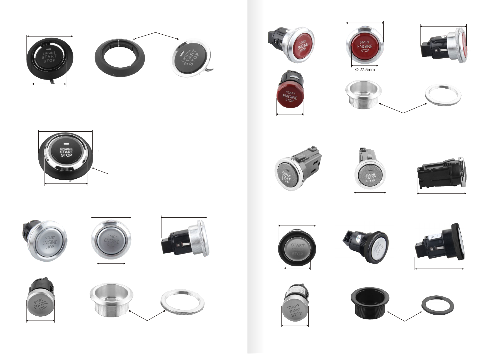
Push start button x1
Alarm high frequency antenna: x1(with red color connector)
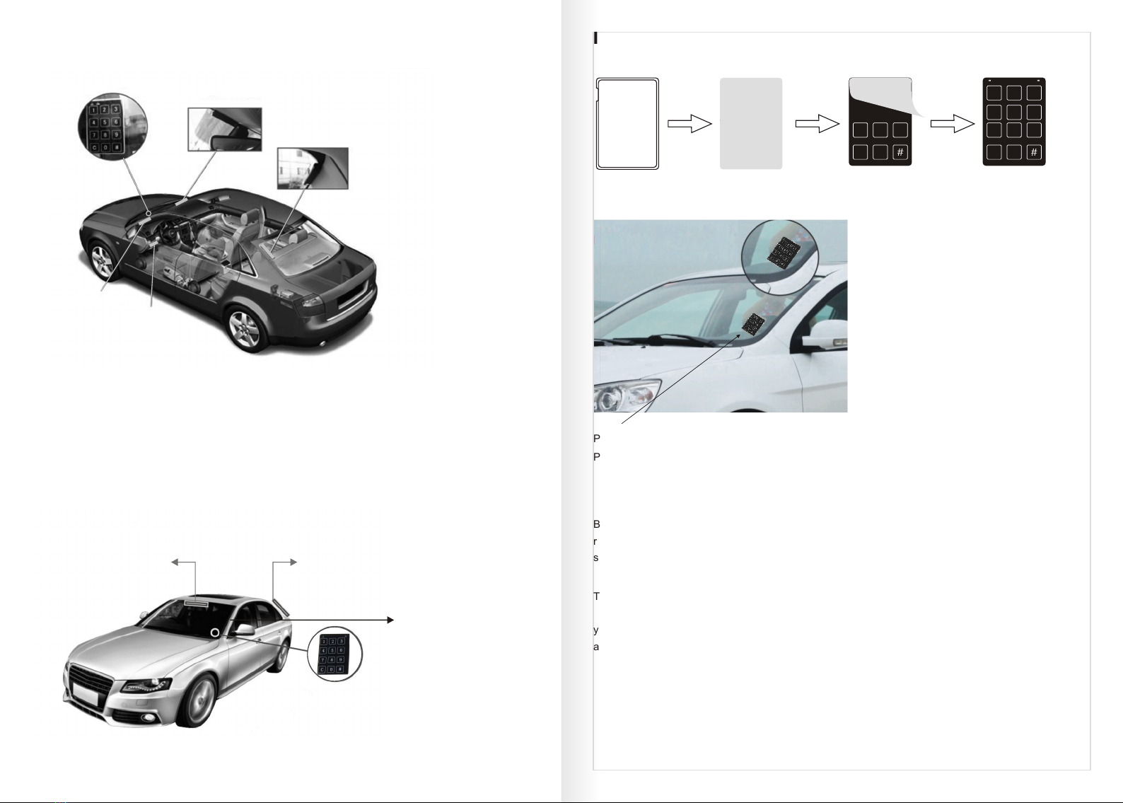
PKE antenna: x2
Touch password keypad: x1
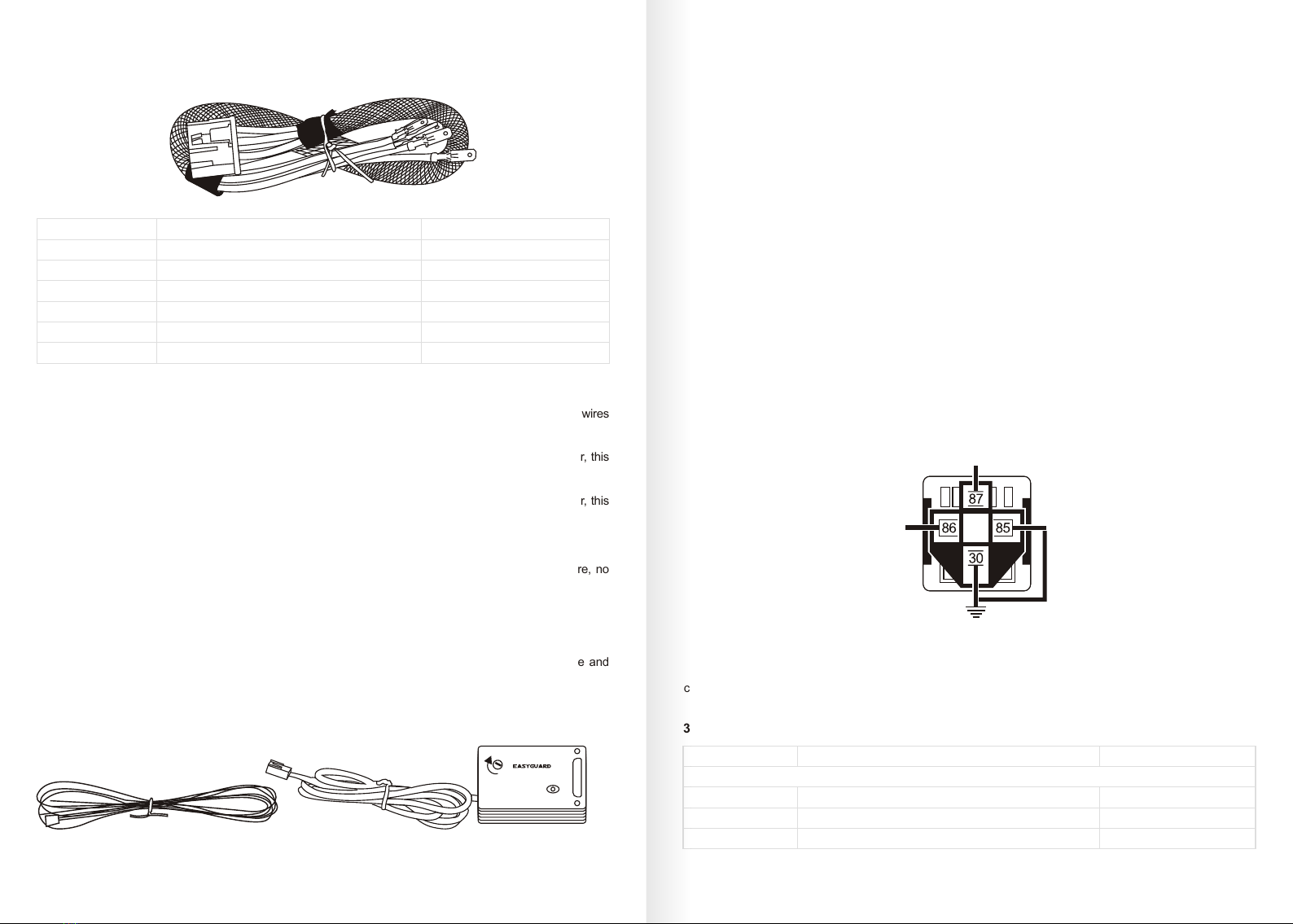
6P ignition wire harness: x1
20P wire harness: x1
3 color (orange, white, yellow) GWR wire x1 or (shock sensor x1)
Note: if the device equip with 3 color (orange, white, yellow) GWR wire, then there is no shock sensor in the
kit, vice versa.
English user manual & wiring diagram x1
-02-
© EASYGUARD Electronics. All right reserved.
1.Before Starting the Installation
Please read all the installation guide before starting the installation. The installation of this PKE car alarm with
remote start system requires interfacing with many of the vehicle’s systems. Many new vehicles use low-
voltage or multiplexed systems that can be damaged by low resistance testing devices, such as test lights
and logic probes (computer safe test lights). Test all circuits with a high quality digital multi-meter before
making connections.
Do not disconnect the battery if the vehicle has an anti-theft-coded radio. If equipped with an air bag, avoid
disconnecting the battery if possible. Many airbag systems will display a diagnostic code through their warning
lights after they lose power. Disconnecting the battery requires this code to be erased, which can require a
trip to the car dealer.
To avoid accidental battery drainage, turn off the interior lights or remove the dome light fuse.
Roll down a window to avoid being locked out of the car.
Installation Guide
This product is intended to be installed by a professional car alarm installer only! Any attempt to install this
product by any person but not a trained professional car alarm installer may result in severe damage to the
vehicle or the components.
If user want to do the DIY installation, please study all the user manual and wiring diagram carefully before
you start installation and only make sure you understand everything then start the installation. You may need
to search on the internet for your vehicle wiring diagram if necessary, and learn how to find the related wires
and how to connect them properly.
Once you find correct wires, please solder them well or use crimp connectors to connect the wires well when
finished the wire connection to avoid any loose up when the vehicle running and cause the device failed to
work. If there is any questions, please contact EASYGUARD authorized dealer or contact EASYGARD
electronics directly for help.
IMPORTANT:
The following safety warnings must be observed at all the time:
Due to the complexity of this system, installation of this product must be finished by a professional car alarm
installer or trained alarm installer.
Once the product is properly installed, this system can remote start the vehicle by a command signal from the
remote control Therefore, never operate the system in an area that does not have adequate ventilation. The
following precautions are the sole responsibility of the user; however, authorized EASYGUARD Electronics
dealers should make the following recommendations to all users of this system:
1.Never operate the system in an enclosed or partially enclosed area without ventilation (like a garage).
2. When parking in an enclosed or partially enclosed area or when having the vehicle serviced, please do not
use the remote engine start feature.
3.It is the user's sole responsibility to properly handle and keep out of reach from children all remote controls
and other accessories in the kit to assure that the system does not remote start the vehicle occasionally.
USER MUST INSTALL A CARBON MONOXIDE DETECTOR IN OR ABOUT THE LIVING AREA ADJACENT
TO THE VEHICLE . ALL DOORS LEADING FROM ADJACENT LIVING AREAS TO THE ENCLOSED OR
PARTIALLY ENCLOSED VEHICLE STORAGE AREA MUST REMAIN CLOSED AT ALL THE TIMES.
Safety warning!

There are 6 DIP switches on the control module and each DIP switch function as below:
Switch 1: When press up is with locking output pulse signal once, when press down is with locking output
pulse signal twice. If your central door require once pulse locking signal, please press it up; if your central
door require twice locking pulse signal, please press it down.
Switch 2: When press up is turn off time delay of the door, When press down is turn on time delay of the door .
Switch 3: When press up is with unlock output pulse signal once, when press down is with unlocking output
pulse signal twice. If your central door require once unlocking pulse signal, please press it up; if your central
door require twice unlocking pulse signal, please press it down.
Switch 4: When press up is turn off anti-hijacking function and when press down is turn on anti-hijacking
function. Default is turn on the anti-hijacking function.
Switch 5: When press up is for manual transmission car and when press down is for automatic transmission
car. If your car is manual transmission, please press this switch up; if your car is automatic transmission car,
please press down this switch.
Switch 6: When press up is for turn off return current and when press down is turn on return current
Notes: For Switch 6 default is press up. For some vehicles, need to turn the key to ON position first then the
foot brake is with electricity when stepping on it. For such kind of vehicles, need to press down switch 6. The
switch 6 press down is mainly for some Volkswagen cars usage.
1.We recommend you to set the DIP switch before you making wire connection.
2.If the alarm control module already connect with 6 pin wire harness and you want to re-set the DIP
switches, please follow with below instructions:
a.Un-plug the 6 pin ignition wire harness to cut off power of the device
b.Press down or up the DIP switch you want to re-set
c.Re-plug the 6 pin ignition wire harness to re-power the device
Important:
Only start installation when you receive all the accessories.
If there is missing any parts, please stop installation immediately and contact your vendor right away for the
replacement.
2. DIP Switch Setting on Control Module
Please set the DIP switch on the control module to fit for your vehicle. See DIP switch as below picture:
Some good control module locations are: Above the glove box, inside the center console, above the under-
dash fuse box, or above the radio.
3.Deciding on components locations
Control module
Some things to remember about where to mount the control module:
Never put the control module in the engine compartment!
The first step in hot-wiring a vehicle is removing the driver's side under-dash panel to access the starter and
ignition wires. If the control module is placed just behind the driver's side dash it can easily be disconnected.
When mounting the control module, try to find a secure location that will not require you to extend the
harnesses’ wires. Keep it away from the heater core (or any other heat sources) and any obvious leaks.
-04-
© EASYGUARD Electronics. All right reserved.
-03- © EASYGUARD Electronics. All right reserved.
123456
DIP ON$
123456
DIP ON$
Name
High frequency antenna
PKE antenna (2.9m)
PKE antenna(5.0 m)
Touch password key pad
Connector size
& color
Red, 3pin
Black,3 pin
Black, 3pin
Black, 4pin
Wire length (in)
47.24
114.17
196.85
78.74
Recommend mount position
P1(A pillar near the cab) or
P2(under the steering wheel) position
Inside upper middle front
windshield( P3 position)
Inside upper left of rear
windshield( P4 position)
Inside of front windshield
( P5 position)
The high frequency antenna is with red color connector (3pin)
Red connector 3pin( )
IMPORTANT:
There are 3 antennas in the kit. Among them, one is alarm high frequency antennas and 2 are PKE antennas.
Here are some information of them respectively:
Antenna & touch password keypad introduction
High frequency antenna:

There are 2 PKE antennas
2.9M PKE antenna 5M PKE antenna
All the antennas are fragile and easy to break, please handle with care when mount them or plug/
unplug them.Please do not pull the antenna to avoid the wires break off.
Here is the recommendation mount position for each of them:
Vertical range Horizontal range
As the PKE antenna is a directional antenna, the PKE induction range will be affected by the antenna
placement/mounting position.
Position A Position B Position C
2.9M PKE
antenna
4M PKE
antenna
2.9M PKE
antenna
4M PKE
antenna
2.9M PKE
antenna
4M PKE
antenna
PKE antenna mount position
Position B is the most common and widely used one.
Some suggestions about the PKE antenna mount position for different vehicles:
For sub compact, compact & sedan:
For optimal performance, mount the 5M PKE antenna in the headliner or below the rear deck.
IMPORTANT:
Mount the PKE antenna in the trunk will greatly affect and reduce the PKE induction range and overall
system working performance.
Pickup (with cab) & cargo:
Mount the 5M PKE antenna in the bumper, behind the license plate.
Pickup (without cab):
Recommend the PKE antenna on position C. the PKE antennas should be mounted on the driver and
passenger side as the tailgate does not require to be controlled.
Convertible:
Mount the 2.9M PKE antenna in front windshield pillar on driver side and the 5M PKE antenna behind
the rear seats.
Note: On vehicle with fiberglass bodies or convertibles, the PKE induction range will be increased.
Never mount the PKE antennas on any metallic surface as this will decrease the PKE induction range
obviously
In order to have a stable PKE induction range, secure the PKE antenna & make sure they will not
move or dangle
The PKE antennas are fragile & easy to break, pleas handle with care when mounting them or
plug/unplug them when installation. Please also make sure they are mounted on a solid (non-flexible)
surface.
Recommended PKE antenna mount position
The recommended PKE antenna mount position is for reference only. And we’d like to recommend you
to adjust the PKE antenna mount position to get a maximum PKE induction range.
Warning:
PKE antenna
-06-
© EASYGUARD Electronics. All right reserved.
-05- © EASYGUARD Electronics. All right reserved.

Installation for password keypad
P5: The touch password keypad mount position
P5: Inside of front windshield
How to mount the touch password keypad?
1.Tear off the sticker on the password keypad
2.Stick the touch password keypad on the left
bottom of inside of front windshield( the position
should be easily & convenient for you to input
the password)
3.Make sure there is no explosion proof film on
the area where you plan to mount the touch
password keypad
Before making your connections, plan how your wires will be routed through the vehicle. For instance, the
red 12V constant input and the remote start ignition wires will often be routed together to the ignition
switch harness. In order to keep the wiring neat and make it harder to find, you may wish to wrap these
wires together in electrical tape or conceal them in tubing similar to what the manufacturer used.
There are two acceptable ways of making a wire connection - solder connections and crimp connectors.
When properly performed, either type of connection is reliable and trouble-free. Regardless of whether
you solder your connections or you use mechanical type crimpon connections, ensure that all connections
are mechanically sound and that they are insulated.
Cheap electrical tape, especially when poorly applied, is not a reliable insulator. It often falls off in hot
weather. Use good-quality electrical tape or heat shrink.
Never twist-and-tape the wires together without soldering.
Never use “fuse taps”, as they can damage fuse box terminals.
-08-
© EASYGUARD Electronics. All right reserved.
-07- © EASYGUARD Electronics. All right reserved.
P1: A pillar near the
cab in the car
P3
P5
P4
Important:
All the recommend mount position is for reference only and user can adjust the mount position to get a
maximum antenna working range
Try your best to keep all the antennas away from any metal product.
P5
P3
P4
P1
P2
P5: The touch password
keypad mount position
P5: Inside of front windshield
in the car
Once finish mount the PKE antenna, the front PKE
antenna and the rear PKE antenna looks like “T” shape
P3: The shorter PKE antenna mount position
P3: Inside of middle upper of the front
windshield in the car
P4: The 5M PKE antenna mount position
P4: Inside of the left upper of the rear
windshield in the car
P1 or P2: High frequency antenna mount position.
P1: A pillar near the cab in the car
P2: Under the steering wheel
User can choose to mount the high frequency antenna on PI or P2 position.
Back Face Tear off the sticker Password keypad
3M 300LSE
3M 300LSE
3M 300LSE
3M 300LSE
3M 300LSE
3M 300LSE
3M 300LSE
3M 300LSE
3M 300LSE
3M 300LSE
78 9
0C
3M 300LSE
3M 300LSE
3M 300LSE
3M 300LSE
3M 300LSE
3M 300LSE
3M 300LSE
78 9
0C
12 3
LED1 LED2
45 6
NOTE:
If you do not want to use touch password
keypad entry function, no need to
install/mount the touch password keypad.
Making Your Wiring Connections

Wire colors
Orange
White
Brown
Red
Red
Yellow
Wire usage
Connect with Accessory(ACC)
Connect with ignition 1 wire
Connect with ignition 2 wire
Connect with constant +12V
Connect with starter wire
Remark
See note 5,7
See note 2,4
See note 3,4
See note 1
See note 1
See note 6
NOTE (1-7):
1.If there is only one +12V wire in your vehicle ignition wire harness, then connect it with both +12V red wires
in ec002;
2.White ignition 1 wire: When turn the key to ON or ACC, this wire with electricity, when starting the car, this
wire still with electricity;
3.Brown ignition 2 wire: When turn the key to ON or ACC, this wire with electricity, when starting the car, this
wire will cut off power suddenly at the moment of starting the vehicle;
Once the vehicle is started, both white & brown wire are with electricity.
4.If there is only one ignition wire in your ignition wire harness, connect it with the white ignition 1 wire, no
need to connect the brown ignition 2 wire
5.If there are 2 ACC wire in your ignition harness, connect both ACC wires with orange wire in ec002.
6.If there are 2 starter wires in your ignition harness, connect both starter wire with yellow wire in ec002.
7. If your car is newer cars that no ACC( only ON & OFF), connect the orange ACC( Accessory) wire and
white ignition 1 wire in EC002 wire harness with ignition 1 wire in your vehicle.
2.ABC 3 color GWR (ground while running) wire (see Note 8) or shock sensor (see note 9)
connect with GWR(-) from bypass module
Connect with
EC002 ACC or
ignition 1
(ACC is recommend)
connect with chassis ground(GND)
You can also use a SPDT relay to generate a GWR wire and wiring method is the same but no need to
connect 87a on SPDT relay.
Wire colors
Yellow/black
The 1st row 10 pin wires
Wire usage
Turn signal light/parking light(+)
See central door locking installation
Remark
3.20-Pin wire harness
Brown
Brown
-10-
© EASYGUARD Electronics. All right reserved.
-09- © EASYGUARD Electronics. All right reserved.
Note 8:
If the alarm equip with 3 color GWR wire, which is used to connect with immobilizer bypass wire or GWR
wire or status output wire
Connection method:
No need to connect orange wire for all below method:
Method 1: Cut off the car factory chip immobilizer wire into 2 parts, each end connect with the white
&yellow wire respectively.
Method 2: if there is GWR(-) wire, connect the GWR(-) wire with white wire and connect yellow wire with
chassis ground(GND)
Method 3:If there is key sense wire which require either ground(-) or positive(+) wire, connect the key
sense wire with white wire and connect the yellow wire with chassis ground(-) or +12V respectively.
Note 9:
If the alarm is equip with shock sensor, then connect with shock sensor. If so, there will be no GWR wire
in the kit and you can use the SPST relay to generate a GWR wire. Method is as below:
3 color GWR wire
M A K
L E D
Shock sensor
If your kit is with 3 color GWR wire, then there is no shock sensor, vice versa.
1.6-Pin ignition wire harness
Main wire harness introduction IMPORTANT:

Note 10
Wiring method for blue/black door trigger wire
The blue/black door trigger wire (-) default setting is negative (-) door trigger
wire with jumper. See diagram as right:
Note 11:
Wiring method for fuel pump wire
The Blue fuel pump wire is recommend to connect with fuel pump wire or oil pump wire/oil pressure wire or
the sucker motor wire in your vehicle.
If you can’t find those wires, please connect it with constant 12V wire or tach wire. This wire usage is to
detect whether the car is started succeed or not & should be well connected.
Note 12:
Wiring method for purple trunk positive/negative selection wire
For the purple trunk positive/negative selection wire, if your trunk is positive trigger(+), please connect this
wire with constant +12V wire; if your trunk is negative(-) trigger, this wire connect with chassis ground.
White/black
Orange/black
Yellow
White
Orange
Pink
Green wire
Orange
Red
Black
Black
White
Blue/black
Blue
Green/black
Green
Purple
The 2nd row 10 pin wires
Unlocking wire, see central door locking installation
See central door locking installation
Locking wire, see central door locking installation
See central door locking installation
Output of factory horn(-)
For GPS module, not used, insulate separately
Footbrake wire(+)
+12V wire for GPS module, not used, insulate separately
Chassis ground(-)
Chassis ground(-)
For GPS module, not used, insulate separately
Negative Door trigger input wire(-)
Fuel pump wire(+)
Trunk release
Output of trunk/trunk motor
Trunk positive/negative selection wire
15A
15A, see note 16
-300mA, see note 17
See note 10,18
Can be changed to positive(+)
by jumper, see note 10, 18
See note 11
See note 12
See note 15
See note 15
see note 13,14
see note 13,14
1 2 3 4 5 6
trunk motor
cut off the trunk wire
Output of the trunk
connect with +12V wire
Purple wire
Green wire
Green/black wire
Note 13
Wiring method of negative (-) trigger of the trunk
Note 14
Wiring method of Positive (+) trigger of the trunk
If the trunk is positive(+) trigger wire, need to cut off the trunk wire in half, the green wire is connect with the
output of the trunk wire and the green/black wire is connecting with trunk motor wire respectively. Like 8th
generation Accord of Honda, need to connect in this way.
1 2 3 4 5 6
Purple wire chassis ground
Green wire output of trunk/trunk motor
Green/black wire No need to connect, insulate separately
Note 15
Wiring method of black chassis ground wire
We recommend that you do not use a factory ground. Ground all your components including the siren, to the
same point in the vehicle, (preferably the kick panel). Scrape away any paint and use a factory bolt or make
your own ground with a self-tapping screw and a star washer.
Please use a factory bolt or screw to attach all the black chassis ground wires securely as the photo show as
below:
Factory bolt chassis ground wire
- -12
© EASYGUARD Electronics. All right reserved.
-11- © EASYGUARD Electronics. All right reserved.
Door trigger jumper, defaut is negative(-)
If your car is with positive door trigger wire, please reset it with below instruction:
a. Un-screw & open the alarm control module
b. Take out the jumper and reset it to be positive (+)
see wiring diagram as right:
door
Positive door trigger (+) setting
Once you re-set with the door trigger jumper to be positive (+), the blue/black door trigger wire is changed
to be positive(+) now.
door
Negative door trigger(-)( by default)

- -14
© EASYGUARD Electronics. All right reserved.
-13- © EASYGUARD Electronics. All right reserved.
Mount it where a thief cannot easily disconnect it, whether the hood is open or shut. Both the siren and its
wires should be difficult to find. This usually involves disguising the wire to look like a factory harness.
We do not recommend grounding the siren to its mounting screws. Instead, we recommend running both
the red and black wires into the passenger compartment and grounding to one common point for all
devices. Both wires are the same length and come already bonded together to make it easier. Whenever
possible, conceal your wires in the factory harnesses or in the same style loom as the factory.
When possible, place the siren on the same side of the vehicle as the control module, where its wires will
reach the control module’s wires without extending them. Always run the wires through the center of a
grommet, never through bare metal!
When installation the siren, please make sure which is downward for waterproof consideration
Note 18
Dome light supervision (optional)
If there is dome light wire and you want to use dome light supervision, please follow with below
instruction:
a.No need to connect the blue/black door trigger wire in 20 pin wire harness
b.Un-plug the 6 pin ignition wire harness to cut off power of the device first
c.Press down DIP switch 2 on alarm control module & wait for around 5 minutes
d.Re-plug 6 pin ignition wire harness to re-power of the device.
Then you should able to use dome light supervision function now.
Some things to remember about mounting the siren:
Keep it away from heat sources, such as radiators, exhaust manifolds, turbo-chargers, and heat shields.
Note 16
Window closer module wire connection with Ec002
If there is window closer module has a wire need to connect with EC002, please connect the white locking
wire in central door locking with the wire from the window closer module.
Note 17
Wiring method of horn or siren
The device default design is to connect with car factory horn with negative (-) 300mA output. If your vehicle
factory horn is negative output, you can connect it with the pink wire of the device EC002 directly.
Pink(-300mA)
123456
Car original horn
Connect with negative power
wire of horn output
Connect with car OEM horn
If your horn is positive output or you are connect with an electrical siren like 6 tone or 1 tone siren, please use
a SPST relay to change the polarity first, here is the method:
Connect with horn or siren 12V+
Connect with pink wire of Ec002
Connect with fused 12V+
Note:You can also use a SPDT relay to have a GWR wire and wiring method is the same but no need to
connect 87a on SPDT relay.
There are 6 types engine start button available for optional as below:
The device default is equip with P1 style push start button, user can choose their preferred engine start
button style.
Engine Start Button Introduction

P2 style engine start button
P1 button size: Ø 41x10mm(no rubber)
Ø 52x10mm(with rubber)
The outer rubber ring is detachable.
P1 style engine start button
P3 style push start button
P1 button size: Ø56x10mm(with rubber), Ø 41x10mm(no rubber),
The outer rubber is detachable.
Ø10mm
Ø56mm
Ø 41mm
Button thickness is 10mm
Ø52mm
Ø 41mm
47mm Ø 38mm
Ø 27.5mm
Ø 27.5mm The ring is detachable
P7n style engine start button
P4 style engine start button
P5 style engine start button
Ø 38mm
Ø 27.5mm
47mm
Ø 27.5mm The ring is detachable
64mm
Ø 41mm
47mm
Ø 38mm
Ø 27.5mm
Ø 27.5mm
The ring is detachable
-16-
© EASYGUARD Electronics. All right reserved.
-15- © EASYGUARD Electronics. All right reserved.

Engine start button color changes for different operation
Key FOB Buttons Introduction & Function Description:
Trunk release/start buttonArm/Panic mode
blue
blue
red
red
blue
red
When
engine
cut off
& key in
PKE
range
Turn off
Turn off
Turn off
Turn off
Turn off
Turn off
When
armed
blue
blue
red
red
blue
red
When
disarm
blue
blue
red
red
blue
red
Turn on
ACC
blue
blue
red
red
blue
red
Turn on
ON
green
red
red
red
Light
red
red
When
started
engine
Turn off
Turn off
Turn off
Turn off
Turn off
Turn off
When
engine
cut off &
key out
of PKE
range
P1
P2
P3
P4
P5
P7n
Engine
start
button
style
Blinks
blue
color
Blinks
blue
color
Blinks
blue
color
Blinks
red
color
Blinks
red
color
Blinks
red
color
Stepping
On foot
brake
pedal
Button
size(mm)
Ø 41x10
(no rubber)
Ø56x10
(with rubber)
Ø 41x10
(no rubber)
Ø52x10
(with rubber)
Ø27.5x47
(no ring)
Ø38x47
(with ring)
Ø27.5x47
(no ring)
Ø38x47
(with ring)
Ø41x64
Ø27.5x47
(no ring)
Ø38x47
(with ring)
LED indicator
Disarm
Start button/
trunk release
Start button/
trunk release
Spare key
Arm/Panic mode
1.Lock/Arm: press lock button once(turn off PKE function)
2.Unlock/disarm: press unlock button once(turn on PKE
function)
3.Remote engine start: In arm status, keep pressing the start
button for around 3 seconds. Please keep at least 8 meters
away from the vehicle when use remote engine start function.
4.Remote engine cut off: Once the vehicle is remote started,
keep pressing the start button for around 3 seconds will remote
cut off the engine. Please keep at least 8 meters away from the
vehicle when use remote engine cut off function.
Arm/Panic mode
Disarm
LED indicator
Spare key
Start button/
trunk release
P
LED indicator
Disarm
Spare key
Arm/Panic mode
Start button/
trunk release
1. Lock/Arm: press lock button once(turn off PKE function)
2. Unlock/disarm: press unlock button once(turn on PKE function)
3. Remote engine start: In arm status, keep pressing the start button for around 3 seconds. Please keep at
least 8 meters away from the vehicle when use remote engine start function.
4. Remote engine cut off: Once the vehicle is remote started, keep pressing the start button for around 3
seconds will remote cut off the engine. Please keep at least 8 meters away from the vehicle when use
remote engine cut off function.
5. Panic mode: in arm status, press lock button once
6. Remote trunk release: Continue to press start button twice.
7. Spare key( default is without, and we recommend you to equip one for future emergency usage)
5.Panic mode: in arm status, press lock button once
6.Remote trunk release: Continue to press start button twice.
7.Spare key( default is without, and we recommend you to equip one for future emergency usage)
-18-
© EASYGUARD Electronics. All right reserved.
-17- © EASYGUARD Electronics. All right reserved.

Arm/Panic mode
Disarm
Start button/
trunk release
Important: The PKE feature default is turn on. When PKE feature is turn on, press lock button once
will turn off the PKE function and lock the car door at the same time. If user want to turn on PKE feature
again, just press unlock button once will turn on the PKE function, at the same time the car door is
unlocked.
1.Mute alarm: Turn off the car, lock/arm the alarm, keep pressing lock button for 3 seconds, turn signal lights
flashes twice, siren beeps twice, the alarm is enter into mute alarm function. When the alarm is in mute alarm
status, the siren will not beep when lock or unlock the car door.
2.Audible alarm (exit mute alarm): Turn off the car, lock/arm the alarm, keep pressing lock button for 3
seconds, turn signal lights flashes once, siren beeps once, the alarm is enter into audible alarm function.
3.Valet mode(Car washing mode): Started the car, stepping on foot brake pedal, keep pressing lock &
unlock button on key fob at the same time for 5 seconds, siren beeps 5 times and turn signal light flashes 5
times. The alarm is enter into valet mode (car washing mode) & turn off PKE function. When the alarm is in valet
mode, user can’t use remote engine start function.
4.Exit valet mode (car washing mode): Started the car, stepping on foot brake pedal, keep pressing lock &
unlock button on the key fob at the same time for 5 seconds, siren beeps 3 times and turn signal light
flashes 3 times. The alarm is exit valet mode (car washing mode) & turn on PKE function.
Other common used function:
1.Lock/Arm: press lock button once(turn off PKE
function)
2.Unlock/disarm: press unlock button once(turn on
PKE function)
3.Remote engine start: In arm status, keep pressing
the start button for around 3 seconds. Please keep at
least 8 meters away from the vehicle when use
remote engine start function.
4.Remote engine cut off: Once the vehicle is remote
started, keep pressing the start button for around 3
seconds will remote cut off the engine. Please keep at
least 8 meters away from the vehicle when use
remote engine cut off function.
5.Panic mode: in arm status, press lock button once
6.Remote trunk release: Continue to press start button
twice.
Please refer to above key fob button introduction to operate related function accordingly.
The remote control is an intelligent electronic device with inductive function. Please follow the following
instruction to avoid damage.
1.Don’t put the remote control in an environment with damp, sunshine or high temperature.
2.Don’t dismantle the remote control. The users can’t inspect the components inside.
3.To avoid strong strike or heavy crash.
4.Don’t put the remote control together with the metal keys or avoid damage or signal shielding.
5.Don’t put the remote control with cell phone or other products will emit strong signal to avoid the signal
interference.
6.When one remote control is using, the other remote control will be in sleep mode to save power. If you want to
activate it, press any button on it will activate it.
If the PKE function of the smart remote control is not working well or the LED indicator is dim or not lit, it’s
probably due to the battery is low. If so, please check the battery of the remote control and replace it with a new
one.
5. Attention: If there is chip immobilizer in
factory original key or remote control, need
to take out the chip immobilizer and hide
it inside or near the ignition cylinder. Please
refer to installation for chip immobilizer. If you
can’t find the chip by yourself. Just hide the
original key or remote control in or near the
ignition cylinder. (Please remember to take
out the battery of the remote if you do so).
6 Everything finish like
the picture:
. 7. If you don’t want to cut the key
for releasing the steering lock, you
can make a hole in the car which
near the steering and install the
push start button .Like the picture,
but it will not convenient for you
as you need to use the original key
to release the steering lock every
time you start the car.
8. Un-plug the
factory ignition
wire harness to
avoid which
consume the
vehicle battery
power.
-20-
© EASYGUARD Electronics. All right reserved.
1. Please check whether there is steering lock in your vehicle or not, if yes, follow with the next step.
2. Copy a key blade with your factory original key blade and match them so that the copied key blade can start
the car.
3. When finish matched, put the copied key blade into the ignition cylinder of car, like this picture,
Manual for releasing the steering lock:
turn the key to
“ON” position.
Inside the lock
So that the steering lock can be turn round. Then cut and keep 1mm
length of the copied key outside of the lock. See the picture:
Cut the key
Outside the lock
Inside the lock
Cut & keep 1mm outside
Stick on
the lock
4. Stick the push start button on the lock. .
(That is the reason for cutting the key.)
-19- © EASYGUARD Electronics. All right reserved.

Method 2:
Use a screw driver and push it into the hole of the
ignition cylinder (see photo on the left), turn the
ignition key to ACC position, then pull out the key
with force will take out the ignition cylinder.Then
remove wires from ignition switch and put the push
start button over the empty key cylinder slot.
Important:
Only a qualified staff can do this as there is risk
to lock the steering lock again if the operation is
not correct. If you are not a qualified staff, we
recommend you to use the method 1 to release
the steering lock.
push here
then pull out
the cylinder
3.Stick the chip immobilizer on the induction of car
coil, make sure the induction of chip and coil is
good. Chip
Foam or other materials
Induction coil of original car
Coin or other metal pad
2.Put the car original remote control(include the chip
immobilizer) into the coil, make sure the induction of the
chip immobilizer and the coil is good.
Installation for chip immobilizer
If there is chip immobilizer in original key fobs, please follow below method
Method 1:
1.Take out the original induction coil from the ignition lock.
Car original
induction coil
Method 2:
1.Take out the chip immobilizer from the car OEM
remote control.
2.Take out the original induction coil from the
ignition lock.
Car original
induction coil
Reminder: Some chips are with weak signal and is hard to start the car when put on the car original coil.
Then need to add a coin or other metal pad underneath the chip to enlarge the signal of it (see above drawing)
Method 3:
Use an extra bypass module to bypass it, installation steps as below:
2.Taping induction wires 2-3 circles on
the ignition lock header
Important:
remote control and induction wire well
around the ignition lock header to make
sure that the car can be started.
Please fix the car OEM
Programming method:
Important:
When you do the programming, please remember to keep pressing the programming switch on the control
module all the time till you finish the programming on both remote controls. Once the vehicle is enter
programming status, need to finish both key fobs programming in 10 seconds.
The alarm can program 2 key fobs maximum.
The key fob is programmed with the control module already before out of the factory and no need to program
them again.
Programming
switch
1.Put the whole remote control (please remember to take out battery from remote if you do so) include the chip
immobilizer into the bypass module.
Note: if size of remote control is big, user can put PCB or chip inside the bypass module.
Bypass
module
Car OEM
remote control
must fix well
in induction
coil Induction wire taping
on the ignition lock
Fix the
induction
wire well on
the ignition
lock with
electrical tape
Induction coil
1.In disarm status, keep pressing the programming switch on the control
module (refer to programming switch) till turn signal light keep lighting
on, this means the alarm is entering into programming status. At this
time, take the 1st remote control close to the control module & keep
pressing lock button on the first remote control, the turn signal light flash
once, this means the first remote control is finished programming.
2.Take the 2nd remote control close to the control module & keep
pressing lock button on the 2nd remote control, turn signal light flash
twice, this means the 2nd remote control is successfully code learned.
After that, release the pressing on the programming switch and the
programming is finished.
User can use this method to add new key fob on the device.
-22-
© EASYGUARD Electronics. All right reserved.
-21- © EASYGUARD Electronics. All right reserved.

Central Door Locking Wire Connection
Checking your locking system
Please use a diode test lamp (voltmeter) for checking electric currents. Conventional test lamps conduct
too high voltage will cause damages to electronic control device. Please take care not to connect the
remote control with the “motor wire” of your central locking system as which may lead it to short-circuit
danger!
Before installation the door panels again, check the following:
1.Make sure your vehicle key is not inside the vehicle;
2.Attach the battery again;
3.Close the vehicle doors well;
4.Check the functionality of the central locking system by closing and re-opening the doors with your car
key, lock the vehicle again.
This item has door lock relays on the PCB and can directly interface with most electric power door lock
systems that drawing 20 amps or less. It can also drive aftermarket actuators directly. Some vehicle
require that an aftermarket actuator be added to the driver’s door to allow system control, see type D
wiring section.
Note: The most common type of door lock systems are Type A positive trigger, Type B negative trigger
and Type C reverse Polarity. Other Types D to type H probably require external relays when do the
installations.
Type A: Positive trigger with three-wire (+) pulse controlling factory lock relays.
Type B: Negative trigger with three-wire (-) pulse controlling factory lock relays.
Type C: Reverse polarity, positive triggered
Type D: Adding one or more aftermarket actuators. These include central locking systems without an
actuator in the driver’s door, but with factory actuators in all the other doors. Type D also includes vehicles
without power locks, which will have actuators added.
Type E: Electrically-activated vacuum systems. The vehicle must have a vacuum actuator in each door.
Making sure that locking the doors from the driver’s or passenger side using the key activates all the
actuators in the vehicle. This requires a slight modification to the door lock wire harness.
Type F: One-wire system: cut to lock, ground to unlock.
Type G: Positive (+) multiplex. One wire controls lock and unlock using resistor(s).
Type H: Negative (-) multiplex. Same as Type G system, but uses (-) pulse instead.
Here is the EC002 series central door lock wire harness principle:
Orange
White
Yellow
Orange/black
White/black
Yellow/black
NC
COM
NO
NC
COM
NO
Lock
Unlock
(Lock signal)
(Unlock signal)
Common,
Normally Open
Normally Closed
Common,
Normally Open
Normally Closed
Lock relay,
Unlock relay,
Lock relay,
Lock relay,
Unlock relay,
Unlock relay,
Type A: positive trigger with three-wire (+) pulse controlling factory lock relays.
There are 3 wires(+) pulse controlling factory locking relays, one pulses 12v for lock, one pulse 12V for
unlock, the last one is for constant 12V.
Depending on the type of the door lock system, there may be additional wires in the door lock harness
and they are not required used in wiring the door locks.
This item has door lock relays on the PCB and can directly interface with most electric power door lock
systems that drawing 20 amps or less
For some vehicles, the door locks may be controlled by an optional data bus expansion module. If so, no
door lock interface wiring is required.
Identifying the door lock system
The easiest way to determine which type of door lock system you are working with is to remove the
master locking switch itself, which is usually on the driver’s door or on the center console once you have
determine which type of factory door lock circuit you are working with, and the color codes of the switch
wires to be used, you can usually simplify the installation by locating the same wires in the vehicle’s kick
panel. If no central locking switch is found, the installation may require a door lock actuator.
NOTE: Always retest the wires in the kick panel to be sure they function the same way as the wires on the
switch.
There are 8 different types of door lock systems (Type A - H). Please search the vehicle-specific wiring
instructions online and the chart below to help determine which door lock system your vehicle uses. Most
vehicle factory door lock wires is smaller gauge and located in the driver’s kick panel or under the driver’s
dash.
IMPORTANT:
Here is wiring connection method for each type:
-24-
© EASYGUARD Electronics. All right reserved.
-23- © EASYGUARD Electronics. All right reserved.

Orange
White
Yellow
Orange/black
White/black
Yellow/black
NC
COM
NO
NC
COM
NO
(Lock signal)
(Unlock signal)
EC002 output
Lock
Unlock
NOT USED-Don’t connect (insulate separately)
+12V(vehicle fused +12V constant)
Drivers door
L
UL
NOT USED-Don’t connect (insulate separately)
(+)Door Lock Wire
(+)Door Unlock Wire
central car lock control unit Door Lock Switch
FACTORY LOCK
SWITCH
LOCK UNLOCK
+12V
L
UL
Factory Door
Lock Module
Type B: Negative trigger with three-wire (-) pulse controlling factory lock relays.
Two wires resting open circuit, one pulses ground for lock and the other pulse for unlock.
For this kind of trigger, the vehicle switch will have three wires on it, one wire will test ground all the time. One
wire will pulse (-) when the switch locks the doors, and the other wire will pulse (-) when the switch unlocks
the doors. This type of system is difficult to mistake for any other type.
Orange
White
Yellow
Orange/black
White/black
Yellow/black
NC
COM
NO
NC
COM
NO
(Lock signal)
(Unlock signal)
EC002 output
Lock
Unlock
NOT USED-Don’t connect (insulate separately)
Drivers door
L
UL
NOT USED-Don’t connect (insulate separately)
(-)Door Lock Wire
(-)Door Unlock Wire
central car lock control unit Door Lock Switch
FACTORY LOCK
SWITCH
LOCK UNLOCK
L
UL
Factory Door
Lock Module
Chasis Ground(-)
Chasis Ground(-)
Type C: Reverse polarity, positive triggered
Motor interrupt central locking:Two wires resting at ground, one pulse 12V for lock, the other pluses 12V
for unlock.
Direct-wired reversing-polarity switches. The switches are wired directly to the motors. This type of system
has no factory relays.
Orange
White
Yellow
Orange/black
White/black
Yellow/black
NC
COM
NO
NC
COM
NO
(Lock signal)
(Unlock signal)
+12V
(vehicle fused constant +12V)
+12V
(vehicle fused constant +12V)
Down up
(+)Door Lock Wire
(+)Door unlock Wire
X
X
L
UL
Drivers door
Door lock switch
on the front door
EC002 output
Lock
Unlock
L
UL
+12V
Type D: Adding one or more aftermarket actuators.
For this type of vehicle, there isn’t a motor in the driver’s door( central locking only operates from the driver’s
door). An extra door actuator is required.
These include central locking systems without an actuator in the driver’s door, but with factory actuators in all
the other doors. Type D also includes vehicles without power locks, which will have actuators added.
Vehicles without factory power door locks require the installation of one actuator on each door. This require
mounting the door lock actuator inside the door. Other vehicles may only require one actuator installed in the
driver’s door if all door locks are operated when the driver’s lock is used.
Orange
White
Yellow
Orange/black
White/black
Yellow/black
NC
COM
NO
NC
COM
NO
(Lock signal)
(Unlock signal)
+12V(vehicle fused constant +12V)
Drivers door
EC002 output
Lock
Unlock
chassis ground
+12V(vehicle fused constant +12V)
chassis ground
-26-
© EASYGUARD Electronics. All right reserved.
-25- © EASYGUARD Electronics. All right reserved.

Orange
White
Yellow
Orange/black
White/black
Yellow/black
NC
COM
NO
NC
COM
NO
(Lock signal)
(Unlock signal)
EC002 output
Lock
Unlock
Drivers door
L
UL
Air compressor Door Lock Switch
To electric
vacuum pump
Chassis Ground
X
+12V
(vehicle fused constant +12V)
Type F: One-wire system - cut to lock, ground to unlock.
This types of central door locking system mainly for Japanese driven
Single wire in series negative trigger.
Single wire that pulses negative to unlock, and open circuit to lock.
This type of door lock system usually requires a negative pulse to unlock, and cutting the wires to lock the
door.( for some vehicles, these are reversed).
Type E: Electrically-activated vacuum systems.
Polarity reverses on a single wire to lock and unlock. Please set the door lock/unlock time to 3.5 seconds.
The vehicle must have a vacuum actuator in each door. Making sure that locking the doors from the
driver’s or passenger side using the key activates all the actuators in the vehicle. This requires a slight
modification to the door lock wire harness.
The door locks are controlled by an electrically activated vacuum pump. The control wire will show +12v
when doors are unlock and (-) ground when locked.
NOTE: For this kind of central door locking, must program the lock pulse time to be 3.5 seconds.
Inside pneumatic
lock main engine
Green/blue
main wire
Brown
negative wire
Red/blue
positive wire
Door lock switch
on the car
Orange
White
Yellow
Orange/black
White/black
Yellow/black
NC
COM
NO
NC
COM
NO
(Lock signal)
(Unlock signal)
EC002 output
Lock
Unlock
Drivers door
central car lock control unit
Factory door
lock module
not used (insulate separately)
X
Chassis Ground
Factory switch
Connection when
doors are locked
Connection when
doors are unlocked
not used (insulate separately)
Type G: Positive (+) multiplex. One wire controls lock and unlock using resistor(s).
Single wire positive central locking
Single wire, positive lock, positive unlock.
Two potential (resistor may require) positive trigger.
Single-resistor style: if one resistor is used in the door lock switch/key cylinder, the wire will pulse (+) 12V
in one direction and less than +12V when operated in the opposite direction.
Two resistor type: if two resistors are used in the factory door lock switch/key cylinder, the switch/key
cylinder will read less than +12V in both directions.
Determining the proper resistor values: to determine the resistor values, the door lock switch/key cylinder
must be isolated from the factory door lock system. For testing, use a calibrated digital multi-meter that is
set to ohms.
IMPORTANT: to ensure an accurate resistance reading, do not touch the resistor or leads during testing.
1.Cut the output wire from the door lock switch/key cylinder in half;
2.Test with the meter from the switch side of the cut door lock switch/key cylinder wire to a reliable
constant +12V source. Some good constant +12V references are the power input source to the door lock
switch/key cylinder, the ignition switch power wire, or the (+) terminal of the battery.
3.Operate the door lock switch/key cylinder in both directions to determine the resistor values. If the multi-
meter displays zero resistance in one direction, no resistor is need for that direction.
4.Once the resistor value(s) is determined, refer to the wring diagram for proper wiring.
-28-
© EASYGUARD Electronics. All right reserved.
-27- © EASYGUARD Electronics. All right reserved.

Lock
Unlock
+12V
Door lock switch
key cylinder
Orange
White
Yellow
Orange/black
White/black
Yellow/black
NC
COM
NO
NC
COM
NO
(Lock signal)
(Unlock signal)
Lock
Unlock
Drivers door
EC002 output
central car lock control unit
BCM
+12V (vehicle fused constant +12V)
not used
(insulate separately)
not used
(insulate separately) Lock resistor
(if required)
Unlock resistor
(if required)
Type H: Negative (-) multiplex. Same as Type G system, but uses (-) pulse instead.
Single wire negative central locking
Single wire, negative lock, negative unlock.
Two potential (resistor may require) negative trigger.
Single-resistor style: if one resistor is used in the door lock switch/key cylinder, the wire will pulse ground
in one direction and resistance to ground when operated in the opposite direction.
Two resistor type: if two resistors are used in the factory door lock switch/key cylinder, the switch/key
cylinder will read resistance to ground in both directions.
Determining the proper resistor values: to determine the resistor values, the door lock switch/key cylinder
must be isolated from the factory door lock system. For testing, use a calibrated digital multi-meter that is
set to ohms.
IMPORTANT:
To ensure an accurate resistance reading, do not touch the resistor or leads during testing.
1.Cut the output wire from the door lock switch/key cylinder in half;
2.Test with the meter from the switch side of the cut door lock switch/key cylinder wire to a reliable ground
source. Some good ground references are the ground input source to the door lock switch/key cylinder, or
the battery ground.
3.Operate the door lock switch/key cylinder in both directions to determine the resistor values. If the multi-
meter displays zero resistance in one direction, no resistor is need for that direction.
4.Once the resistor value(s) is determined, refer to the wring diagram for proper wiring.
EC002 output
central car lock control unit
Lock
Unlock
Door lock switch
key cylinder
Orange
White
Yellow
Orange/black
White/black
Yellow/black
NC
COM
NO
NC
COM
NO
(Lock signal)
(Unlock signal)
Lock
Unlock
Drivers door
BCM
not used
(insulate separately)
not used
(insulate separately) Lock resistor
(if required)
Unlock resistor
(if required)
Chassis Ground
Chassis Ground
-30-
© EASYGUARD Electronics. All right reserved.
-29- © EASYGUARD Electronics. All right reserved.

NOTE:(1-7)
Wiring Diagram of EASYGUARD EC002
See DIP switch setting
on Control module
ENGINE
STOP
START
Orange Switch
Blue LED light
Green LED light
Brown 12V
Push start button
Orange wire connect with ACC
White wire connect with ignition 1
Brown wire connect with ignition 2
Red wire connect with +12V
Yellow wire connect with Starter
cut the key and keep
1mm outside
White
( see note 8)
or blue
( see note 9),
3Pin
3 color wire (see Note 8) or shock sensor (see
note 9)
Note 8:
If the alarm equip with 3 color wire, which is used
to connect with immobilizer bypass wire or G R
status wire or status output wire
Choose one method as below:
No need to connect orange wire for all
W
1.If there is only one +12V wire in
your ignition wire harness, then
connect it with both +12V wires in
EC002
2.White ignition 1 wire: When turn
the key to ON or ACC, this wire with
electricity, when starting the car, this
wire still with electricity
3.Brown ignition 2 wire: When turn
the key to ON or ACC, this wire with
electricity, when starting the car, this
wire will cut off power suddenly at
the moment.
Once the car is started, both white
& brown wire are with electricity.
4.If there is only one ignition wire in
your ignition wire harness, connect
it with the white ignition 1 wire, no
need to connect the brown ignition
2 wire
5.If there are 2 ACC wire in your
ignition harness, connect both ACC
wires with orange wire in EC002
6.If there are 2 starter wires in your
ignition harness, connect both
starter wire with yellow wire in
EC002.
7. If your car is newer cars that no
ACC( only ON & OFF), connect the
orange ACC( Accessory) wire and
white ignition 1 wire in EC002 wire
harness with ignition 1 wire in your
vehicle.
Note 9:
If the alarm is equip with shock
sensor, then connect with shock
sensor. If so, there will be no GWR
wire in the kit and you can use the
SPST relay to have a GWR wire.
Method is as right diagram:
You can also use a SPDT relay to
have a GWR wire and wiring
method is the same but no need to
connect 87a on SPDT relay.
below method:
Method 1: Cut off the car factory chip
immobilizer wire into 2 parts, each end
connect with the white & yellow wire
respectively;
Method 2: If there is GWR (-) wire, connect
the G R(-) wire with white wire and
connect yellow wire with ground(GND)
Method 3:If there is key sense wire which
require either ground (-) or positive (+) wire,
connect the key sense wire with white wire
and connect the yellow wire with ground (-)
or +12V respectively.
W
connect with GWR(-) from bypass module
connect with
Ec002 ACC or ignition1
(ACC is recommend)
connect with chassis ground(GND)
Black wire: Ground (GND)
See note 15
(-)
White wire: GPS
Blue wire:
fuel pump wire (+) (see note 11)
Green/Black wire: trunk release see note 13, 14) (
Green wire: Output of trunk/
trunk motor (see note 13, 14)
Purple wire:
trunk positive/
negative selection
Programming
switch
Brown wire: turn signal light (+)
Yellow/black wire
White/black wire
Orange/black wire
Yellow wire
Pink wire: output of horn (-300mA) See Note 17
Orange wire
Green wire
GPS terminal
(optional, Default is
without GPS, only
connect when there is
with GPS tracker)
Orange wire:
foot brake wire (+)
Blue/black door trigger wire(-)
(see note 10, 18)
(see note 12)
Password keypad
If you do not use touch
password entry function,
then no need to connect
this wire.
+12V
The blue/black door trigger wire
default is negative (-), which can
be set by jumper to be positive (+)
(see note 10,18)
Door lamp
Door
switch
+12V
See central
door locking
wire connection
Footbrake
GPS terminal
(optional, Default is
without GPS, only
connect when there
is with GPS tracker)
White wire ( )See Note 16
Black wire: Ground (GND)
See note 15
(-)
High frequency antenna Red 3-pin antenna( )
Low frequency PKE antenna Black 3-pin antenna( )
Low frequency PKE antenna (Black 3-pin antenna)
1 2 3
456
12 3 4 5 6
ON$
DIP
white, 4pin
white, 6pin
white, 20Pin
black, 4 pin
IMPORTANT TIPS:
1.Connect the black chassis ground wires first when making wire connection to avoid damage on the device
2.Once you finish all wire connection, test the function first and remember to use the electrical tapes or strips to
tighten all the wire connection to avoid any poor connection between the control module & wire harness.
Red, +12V wire for GPS module(optional,
default is without GPS module, only connect
when there is with GPS module)
-32-
© EASYGUARD Electronics. All right reserved.
-31- © EASYGUARD Electronics. All right reserved.

Function description:
ENGINE
START
STOP
Push button installation position
1. Push button start/stop
A.When step on foot pedal
1.In disarm status, step on foot pedal, the push button blinks blue color (or red color per the push start button
style you choose), short press the push button once, the vehicle will be started. The push button will turn to
green color (or red color per the push start button style you choose).
Once the vehicle is started, step on foot pedal and press the push button 0.5 second will stop the vehicle. At
the same time, ACC and ON will be turn off and the push button will turn to blue color (or red color per the
push start button style you choose) if the key fob still in PKE induction range.
If the key fob is out of PKE induction range, the push start button will turn off.
2.If the push start button was broken or destroyed or in other situation that unable to use. User can start or
stop the vehicle with below steps:
In disarm status, step on foot pedal, keep pressing start button on the remote control for 3 seconds, the
vehicle will be started.
Step on foot pedal, keep pressing start button 3 seconds on the remote control will cut off the engine and turn
off ACC & ON.
B.When do not step on foot pedal
1.In disarm status, do not step on foot pedal and short press the push button once will turn on ACC. Press
the push button once again will turn on ACC & ON dashboard and press it once again will turn off ACC & ON.
In disarm status, do not step on foot pedal, keep pressing the push start button for 3 seconds will turn off
ACC and ON dashboard and the vehicle engine will be stopped. The push button will turn to blue color (or
red color per the push start button style you choose) if the key fob still in PKE induction range.
If the key fob is out of PKE induction range, the push start button will turn off.
C.Keep pressing the button to start the vehicle
In cold winter or other special situation, user can keep stepping on foot pedal and keep pressing the push
button for 5 seconds to start the vehicle till the vehicle is started. The maximum pressing engine start button time
is 5 seconds. If press 5 seconds but still not able to start the vehicle, please try it again.
Notes: Once the vehicle is armed, then not able to start the vehicle by the push button but need to disarm
first then press the push button to start the vehicle.
D.Remote engine start for back up purpose:
For some special situation such as there is no brake signal or the brake fuse was failed to work, user can use
remote engine start function to start the vehicle, method is keep pressing start button on key fob for 3
seconds will remote start the vehicle, and once the vehicle is started, user keep pressing start button for 3
seconds will cut off the vehicle engine.When use remote engine start/stop function, please keep at least 8
meters away from the vehicle when PKE feature is turn on.
2.PKE(passive keyless entry)
Lock: Turn off the engine, exit the vehicle and close all doors well and walk away from the vehicle for 3-5
meters away with the key fobs, the alarm siren will beep once and turn signal light flashes once to confirm, at
the same time will lock the door & arm the vehicle automatically. At the same time, the push button turn off
and the vehicle window will roll up automatically (extra window closer module is required for some cars).
Unlock: When user approach the vehicle in 1-2 meters with key fob in hand or pocket, the turn signal light
turn on 1 second to confirm, at the same time, the alarm is disarm & car door automatically unlock. The push
button turn to blue color (or red color per the push engine start button style you choose). The user can open
car door and get in the vehicle directly.
5.Mute alarm & audible alarm
Turn off the vehicle, lock/arm the alarm, keep pressing lock button for 3 seconds, siren beeps twice, the alarm
is enter into mute alarm function.
Audible alarm (exit mute alarm): Turn off the vehicle, lock/arm the alarm, keep pressing lock button for 3
seconds, siren beeps once, the alarm is enter into audible alarm function.
4.Manual disarm/unlock
Short press unlock button once will unlock the vehicle door, turn signal light turn on 1 second, the vehicle is
disarmed and car door is automatically unlocked. The push start button will turn on blue (or red color per the
push start button style you choose) and PKE function will turn on at the same time.
3.Manual arm/lock
Short press lock button once will lock the vehicle door, turn signal light flashes 1 second and siren beeps
once. At the same time, will turn off PKE function, the push button also turn off and the vehicle window will roll
up automatically (extra window closer module is required for some cars).
6.Remote trunk release
Continue to press trunk release button twice will remote release car trunk, turn signal light will flash 3
times at the same time.
If there is no trunk release button on the remote control, press start button or siren button twice
will release car trunk.
The default trunk release output is 2.5 seconds, if your trunk require 3 seconds output time, press down DIP
switch 2 on control module in power off status( see DIP switch setting on control module)
7.Panic mode/Car finding
In arm status, press lock button once, turn signal light flashes 5 times and siren beeps 5 times to indicate
car location. Press the lock button once again will stop. Siren will not beep when the alarm is in mute alarm
status.
-34-
© EASYGUARD Electronics. All right reserved.
-33- © EASYGUARD Electronics. All right reserved.

When user use remote engine start function, please pay attention to following points:
(1) Never remote start the vehicle with the vehicle in gear, and
(2) Never remote start the vehicle with the keys in the ignition. The user will be responsible for having the
neutral safety feature of the vehicle periodically checked, where in the vehicle must not remote start while the
vehicle is in gear. This testing should be performed by an authorized EASYGUARD dealer or a professional
car alarm installer in accordance with the safety checking stated in this product installation guide. If the
vehicle starts in gear, cease remote start operation immediately and consult with the user to fix the problem
immediately.
(3). When use remote engine start function, the gear selector should in Neutral (N) or position. If
your vehicle is manual transmission, please refer to remote engine start for manual gear car.
Remote starters for manual transmission pose significant risks if not properly installed and operated. When
testing to ensure the installation is working properly, only remote start the vehicle in neutral gear, on a flat
surface and with a functional, fully engaged parking brake. Do not allow anyone to stand in front of or behind
the vehicle.
(4). EASYGUARD electronics will not bear any responsibility for the loss caused by the running of the vehicle
after remote engine start.
Parking(P)
1.Remote engine start for automatic gear car:
In arm status, keep pressing the start button on the remote control for 3 seconds will remote start the vehicle.
When doing this, please keep a distance of at least 8 meters away from the vehicle (User is not able to use
remote engine start function if in PKE induction area). Siren will beep 3 times and turn signal lights will flash
15 times when car is remote started. If user approached the vehicle with key fob within PKE induction range,
turn signal light will stop flashing. And the door will be automatically locked once vehicle is started.
The started engine will keep on running for 15 minutes then turn off automatically if user doesn’t unlock the
vehicle doors within 15 minutes.
While the engine is remote started, if user approach the vehicle within 1-2 meters with the remote control, the
door will unlock and the alarm will disarm automatically. The user may drive the vehicle directly and there is
no need to start the engine again.
While the engine is remote started, If user approach the vehicle within 1-2 meters with the remote control but
not open car door, then walk away from the vehicle for more than 5 meters away, the vehicle will be
automatically cut off engine and turn off ACC, ON and enter into arm status.
While the engine is remote started, If user approach the vehicle within 1-2 meters with the remote control and
open car door, then walk away from the vehicle for more than 5 meters away with remote control, the vehicle
engine will not cut off and turn signal light will keep lighting on to remind user to close the door well.
Any illegal door opening will trigger the alarm if without induction of the remote control.
Once the vehicle is remote engine started, keep pressing the start button on remote control for 3 seconds will
remote cut off the engine and also turn off ACC & ON. The vehicle will enter into arm status.
2.Remote engine start for manual gear car:
If the engine is stopped by pressing the push start button then user can’t use remote engine start function. If
user want to start the engine with remote control, please set with below procedure:
Un-plug the 6-Pin ignition wire harness from the control module
Press up DIP switch 5 on control module to set the alarm fit for manual transmission car
Re-plug the 6-Pin ignition wire harness with the control module
Park the vehicle, shift the gear selector to Neutral position, pull the hand brake ON, do not turn off the vehicle
engine in the vehicle with the push start button, exit the vehicle and close all the doors well, walk away from
the vehicle at least 5 meters away, then keep pressing the start button for 3 seconds to turn off the engine.
Then next time user can use the remote control to use remote engine start function. (This is to avoid accident
for manual gear cars if the gear selector is not in neutral position when starting the engine with remote
control).
Important: Factory default setting of this system is with remote engine start for automatic gear cars. If your car
is manual gear cars and want to use the remote engine start function. Please follow with above instructions.
Our company will not bear any responsibility for the loss caused by the running of the vehicle after remote
engine start.
10. Dome light supervision (optional)
If you want to use dome light supervision, please follow with below instruction:
a.Dis-connect the blue/black door trigger wire in 20 pin wire harness with the door trigger wire in your vehicle
b.Un-plug the 6 pin ignition wire harness to cut off power of the device first
c.Press down DIP switch 2 on alarm control module & wait for around 5 minutes
d.Re-plug 6 pin ignition wire harness to re-power the device.
Then you should able to use dome light supervision function now.
If you connect the blue/black door trigger wire with the door trigger wire in your vehicle, the turn signal light
will flash when opening the car door.
If you dis-connect the blue/black door trigger wire with the door trigger wire in your vehicle, the turn signal
light will not flash when opening the car door.
8. To enable or disable PKE feature (PKE ON/OFF setting)
To disable PKE feature(valet mode): Started the vehicle, stepping on foot brake pedal, keep pressing lock &
unlock button on key fob at the same time for 5 seconds, siren beeps 5 times and turn signal light flashes
5 times. The alarm is enter into car valet mode & disable the PKE feature.
To enable PKE feature (exit valet mode): Started the vehicle, stepping on foot brake pedal, keep pressing lock &
unlock button on the key fob at the same time for 5 seconds, siren beeps 3 times and turn signal light
flashes 3 times. The vehicle is exited valet mode & enable PKE feature.
Important: The PKE function default is turn on. When PKE function is turn on, press lock button once
will turn off the PKE function and lock the vehicle door at the same time. If user want to turn the PKE
on again, just press unlock button once will turn on the PKE function, at the same time the
vehicle door is unlocked temporary.
9.Remote engine start/stop
For a 3 button remote control, the button except lock button and unlock button is the start button.
For a 4 button remote control the button except lock , unlock & trunk release button is the start
button (usually is siren button)
The alarm has two modes for remote engine start, automatic gear car and manual gear car, please
remember to select correct DIP switch selection on the control module. Default setting is for automatic gear
car with switch 5 in control module is press down.
-36-
© EASYGUARD Electronics. All right reserved.
-35- © EASYGUARD Electronics. All right reserved.
Table of contents
Other Easyguard Car Alarm manuals
Popular Car Alarm manuals by other brands

Clifford
Clifford Concept 450 owner's guide

Clifford
Clifford Novell owner's manual

Directed Electronics
Directed Electronics Python 990 installation guide

Performance Teknique
Performance Teknique ICBM-7071 user manual

Directed Electronics
Directed Electronics 7900 owner's guide

Steel mate
Steel mate 888W1 user manual