Eaton E02A User manual

Eaton Micro Data Center
E02A Integrated rack type air conditioner
User manual

ii E02A INTEGRATED RACK TYPE AIR CONDITIONER UM.ICUBE2.0-IRTAC.SG.0822 August 2022 www.eaton.com
DISCLAIMER OF WARRANTIES AND LIMITATION OF LIABILITY
The information, recommendations, descriptions and safety notations in this document are based on Eaton
Corporation’s (“Eaton”) experience and judgment and may not cover all contingencies. If further information is
required, an Eaton sales office should be consulted. Sale of the product shown in this literature is subject to the
terms and conditions outlined in appropriate Eaton selling policies or other contractual agreement between Eaton
and the purchaser.
THERE ARE NO UNDERSTANDINGS, AGREEMENTS, WARRANTIES, EXPRESSED OR IMPLIED, INCLUDING
WARRANTIES OF FITNESS FOR A PARTICULAR PURPOSE OR MERCHANTABILITY, OTHER THAN THOSE
SPECIFICALLY SET OUT IN ANY EXISTING CONTRACT BETWEEN THE PARTIES. ANY SUCH CONTRACT STATES
THE ENTIRE OBLIGATION OF EATON. THE CONTENTS OF THIS DOCUMENT SHALL NOT BECOME PART OF
OR MODIFY ANY CONTRACT BETWEEN THE PARTIES.
In no event will Eaton be responsible to the purchaser or user in contract, in tort (including negligence), strict
liability or other-wise for any special, indirect, incidental or consequential damage or loss whatsoever, including
but not limited to damage or loss of use of equipment, plant or power system, cost of capital, loss of power,
additional expenses in the use of existing power facilities, or claims against the purchaser or user by its customers
resulting from the use of the information, recommendations and descriptions contained herein. The information
contained in this manual is subject to change without notice.

E02A INTEGRATED RACK TYPE AIR CONDITIONER UM.ICUBE2.0-IRTAC.SG.0822 August 2022 www.eaton.com iii
Table of Contents
1. Introduction ........................................................................1
1.1 Foreword ............................................................................... 1
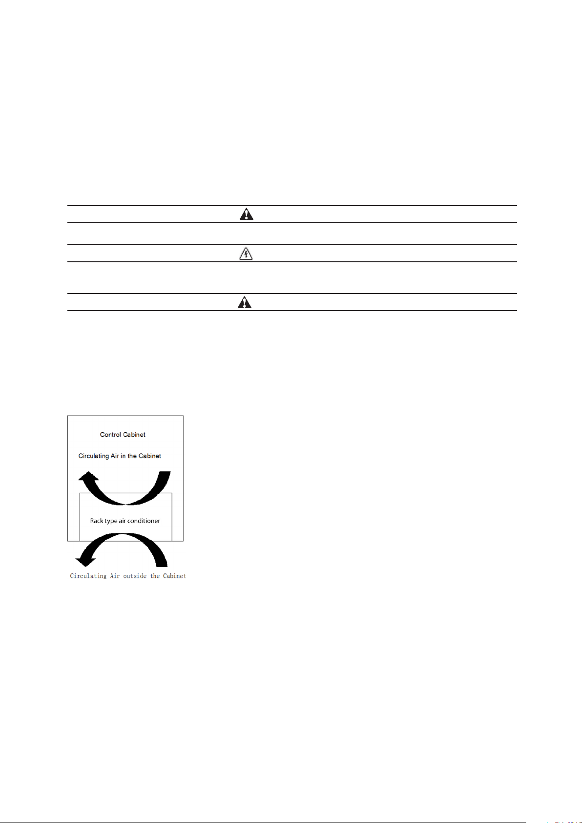
1.2 Air conditioner description .................................................................. 1
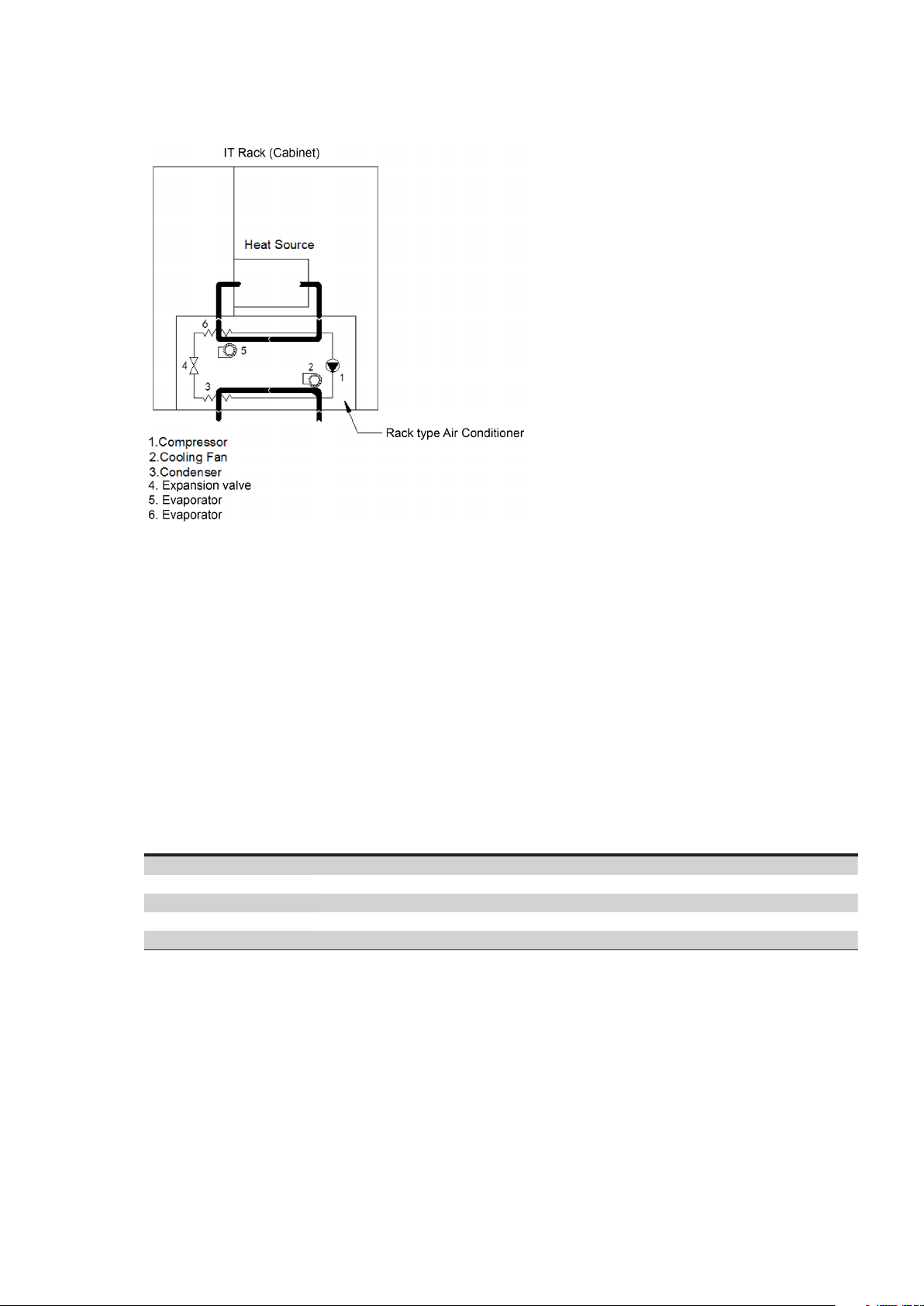
1.2.1 Principles of function ................................................................ 1
1.2.2 Operating conditions ................................................................ 2
1.3 Standards ............................................................................... 2
2. Safety notices ......................................................................3
2.1 Transport................................................................................ 3
2.2 Storage ................................................................................. 3
2.3 Unpacking............................................................................... 3
2.4 Installation .............................................................................. 3
3. Installation and operation ............................................................4
3.1 Mechanical installation ..................................................................... 4
3.2 Electrical installation....................................................................... 4
3.3 Power-on steps........................................................................... 6
4. System function introduction .........................................................7
4.1 Cooling ................................................................................. 7
4.2 Heating (Option) .......................................................................... 7
4.3 Component control mode .................................................................. 8
4.4 Unit sequencing control (option) ............................................................. 8
4.4.1 Time Switching ..................................................................... 8
4.4.2 Temperature switch ................................................................. 8
4.4.3 Both working with high temperature .................................................... 8
4.4.4 Disturbance switching ..................................................................8
4.5 Self testing ............................................................................... 8
4.6 Hydrogen discharging/emergency fan (option) .................................................... 9
4.7 Alarm .................................................................................. 9
4.8 Unit menu structure ........................................................................10
4.8.1 Operation interface ...................................................................10
4.8.2 Menu structure .................................................................... 10
5. Maintenance. . . . . . . . . . . . . . . . . . . . . . . . . . . . . . . . . . . . . . . . . . . . . . . . . . . . . . . . . . . . . . . . . . . . . . .12
5.1 Daily maintenance ..........................................................................12
5.2 Compressor maintenance ....................................................................12
5.3 Common fault. . . . . . . . . . . . . . . . . . . . . . . . . . . . . . . . . . . . . . . . . . . . . . . . . . . . . . . . . . . . . . . . . . . . . . . . . . . 12
5.4 Charge refrigerant ..........................................................................13
5.5 Tools preparation ...........................................................................13
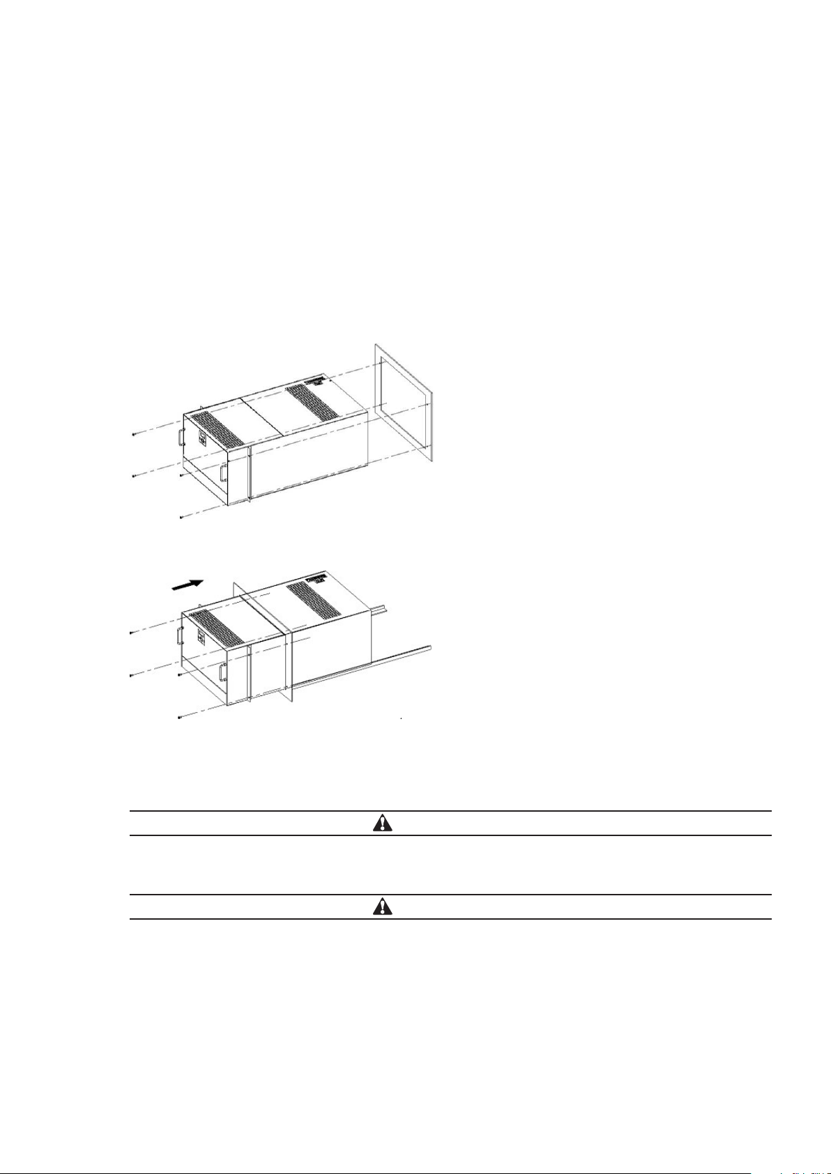
5.6 Disassemble the unit .........................................................................15
5.7 Charge refrigerant ..........................................................................15
5.8 Power on and test the air conditioner...........................................................17
5.9 Reinstall the air conditioner into the cabinet .....................................................17

E02A INTEGRATED RACK TYPE AIR CONDITIONER UM.ICUBE2.0-IRTAC.SG.0822 August 2022 www.eaton.com1
Introduction
1. Introduction
1.1 Foreword
ote:N All of the operations of this product should be performed by professional engineers and technicians.
This manual can only be used to guide the installation and operation of the integrated rack type air conditioner.
The manual content includes the functional description and regular maintenance of the unit. In this manual, the
safety tips and warning signs are described as follows:
DANGER!
If the measures described in the following are not strictly observed there is danger to life and health.
HAZARD!
If the measures described in the following are not strictly observed there is danger to life and health due to
electrical shock.
CAUTION!
If the measures described in the following are not strictly observed material damage may be caused.
1.2 Air conditioner description
The integrated rack type air conditioner is a cooling product developed for the Eaton iCUBE micro data center. This
air conditioner’s frequency can be regulated. It has cooling capacity regulating function, and the fans can regulate
speed automatically.
Figure 1.1 Function Diagram
1.2.1 Principles of function
The refrigerant is compressed by compressor (1) into high temperature and high pressure gas; At the condenser
side (3), the outdoor air is drawn or eliminated from the bottom by the condensing fan (2), the heat will be dissipated
into the surrounding ambient air through the condenser (3), and the refrigerant gas changes to liquid. After passing
through the expansive valve (4), the refrigerant pressure drops and changes to two phase. In the evaporator (6), the
refrigerant absorbs the heat inside the cabinet and evaporates. The evaporation fan (5) will suctioned out hot air from
the inside of the cabinet. After passing through the evaporator, the air is cooled and discharged into the front channel
of the cabinet. At the same time, the air in the cabinet is dehumidified.

2
Introduction
E02A INTEGRATED RACK TYPE AIR CONDITIONER UM.ICUBE2.0-IRTAC.SG.0822 August 2022 www.eaton.com
Figure 1.2 Working Principle Diagram
1.2.2 Operating conditions
• Input Power
220VAC±15%, 50/60Hz
• External Ambient temperature:
-40˚C ~ 50˚C
ote:N Please read the nameplate parameters on the air conditioner carefully. The actual technical parameters shall
be subject to the nameplate name.
1.3 Standards
Standard Description
GB/T 17626.7-1998 EMC
GB470 6.1 Safety of household appliances or similar electric appliance
GB4798.1 Environmental conditions existing in the application of electric and electronic product – Storage
GB4798.2 Environmental conditions existing in the application of electric and electronic product – Transportation
GB4798.3 Environmental conditions existing in the application of electric and electronic product – Use

3
Safety notices
E02A INTEGRATED RACK TYPE AIR CONDITIONER UM.ICUBE2.0-IRTAC.SG.0822 August 2022 www.eaton.com
2. Safety notices
In order to use the equipment correctly, the following safety precautions should be strictly followed.
2.1 Transport
• Keep the air conditioner in a horizontal state during transportation.
• If the cabinet needs to be transported, please remove the air conditioner and pack it separately
before transportation.
2.2 Storage
• Storage environment should not exceed 70°.
• Keep the air conditioner in a horizontal state during storage.
2.3 Unpacking
• Prior to and during unpacking, make a visual inspection of the air conditioner to see whether any damage has
occurred during transportation. Pay special attention to loose parts, dents, scratches and oil leakages.
• Any damage must be reported immediately to the forwarder agent.
• Before disposing of packing material ensure that it does not contain any loose components.
2.4 Installation
• Select a site for the enclosure with good ventilation;
• The location should be free from excessive dirt and moisture;
• The ambient temperature does not exceed +45˚C;
• The enclosure is sealed on all sides (IP54). If the seal is not good, too much condensate may be generated;
• Air inlet and outlet should not be blocked by obstacles inside the enclosure at the inside of the enclosure;
• The duct size outside the air conditioner cabinet should not be less than the limit value in the following figure 2.
• Units are only fitted horizontally in the specified position. The maximum inclination angle shall not be greater
than 2°;
• Losses from the components installed in the enclosure must not exceed the specific refrigeration capacity of
the air conditioner itself;
• The user must not modify the air conditioner in any way.
Figure 2 Distance Diagram

4
Installation and operation
E02A INTEGRATED RACK TYPE AIR CONDITIONER UM.ICUBE2.0-IRTAC.SG.0822 August 2022 www.eaton.com
3. Installation and operation
3.1 Mechanical installation
Before the installation of air conditioner, the fitting surface of cabinet shall be properly opened with vent and
screw hole, where the hole size shall refer to the appearance size figure as provided by the manufacturer.
Mounting:
1 Insert the air conditioner into the cabinet along the guide rail direction.
2 Fix the installation flange on the cabinet’s front surface as shown in the figure 3.1 and 3.2 below:
Figure 3.1 Installation Diagram
Figure 3.2
3.2 Electrical installation
CAUTION!
As the rack type air conditioner is connected to the power supply via the circuit protection device,
the appropriate circuit protection device and the power cable should be chosen according to the air
conditioning nameplate and technical parameters.
CAUTION!
Too high voltage may lead to damage of cabinet air conditioner. Please follow the voltage requirement
marked on the nameplate to switch on the air conditioner.

5
Installation and operation
E02A INTEGRATED RACK TYPE AIR CONDITIONER UM.ICUBE2.0-IRTAC.SG.0822 August 2022 www.eaton.com
CAUTION!
In order to avoid any damaging effects, before turning on the power supply, the cabinet air conditioner
must be reliably earthed.
Figure 3.3
ote:N The power input port identifier is subject to the specific unit silk printing
or
AC input
printing
Figure 3.4
References to common (copper wire) selection:
Rated current ≤5A ≤10A ≤15A ≤25A
Power line diameter 1.0 mm 1.5 mm 2.5 mm 4 mm
Connecting interface (The power input terminal will be subject to application instructions)
Connecting interface:
Port Definition
Power input L1/L L: 220VAC power input cable L; L1: 110VAC power input cable L
L2/N N: 220VAC power input cable N; L2: 110VAC power input cable L
PE Grounding wire of the air conditioner
Alarm output NC The first public alarm dry nod (NC)
COM The first public alarm dry nod (COM)
NO The first public alarm dry nod (NO) (Option)
1The second public alarm dry nod (COM) (Option)
2The second public alarm dry nod (NO) (Option)
Signal input 3N/A
4Hydrogen discharge / emergency fan dry contact (FG) (Option)
5Hydrogen discharge / emergency fan dry contact (NO) (Option)
6Hydrogen discharge / emergency fan dry contact (COM) (Option)
7Door open alarm input (option)
8Door open alarm input (option)
communication ports +RS485 communication ports (+) (Option)
-RS485 communication ports (-) (Option)

6
Installation and operation
E02A INTEGRATED RACK TYPE AIR CONDITIONER UM.ICUBE2.0-IRTAC.SG.0822 August 2022 www.eaton.com
• Alarm output (option):
The unit provides alarm output dry contact. If there is no alarm, the dry contact is close. When there is alarm,
the dry contact will open. Contact capacity: resistive load 5A@30VDC/5A@250VAC.
3.3 Power-on steps
Firstly make sure the AC voltage is in accordance with the standard, and then close the power input switch. 30s
later the internal cycle fan of the unit will be started. After delay time about 3min, the unit select operation mode
according to the unit’s.

7
System function introduction
E02A INTEGRATED RACK TYPE AIR CONDITIONER UM.ICUBE2.0-IRTAC.SG.0822 August 2022 www.eaton.com
4. System function introduction
The operation of the air conditioner is automatically controlled according to the temperature inside the cabinet. The
controller detects the return air temperature by temperature sensor and compares it with the set point to judge,
and then controls the compressor or fan.
4.1 Cooling
Cooling stop point=cooling set point cooling Delta T. When the rack internal temperature exceeds the cooling set
point (CoolingSP), the cooling will start; when the cabinet internal temperature is lower than the cooling stop
point, the cooling stops.
Parameter Default value Setting range
CoolSP 29˚C [20~50]
Cool T3˚C [1~10]
INHT 65˚C [20~80]
Setting point description:
CoolSP: Set point when cooling starts.
Cool T: Temperature control sensitivity.
INHT: Internal high Temp. alarm point.
CAUTION!
For the reliable operation of the unit and the maximum energy efficiency, it is recommended that the user
should not randomly change the temperature set point.
4.2 Heating (Option)
Heating stop point=heating point+heating sensitivity. When the temperature inside the cabinet is lower than the
heating start-up point, the heating will start; when the temperature inside the cabinet is higher than the heating
stop point, the heating will stop.
Parameters Default value Setting range
HeatSP 0˚C [-5~15]
Heat T10˚C [1~15]
Setting point description:
HeatSP: Point when heating starts.
Cool T: Temperature control sensitivity.
CAUTION!
For the reliable operation of the unit and the maximum energy efficiency, it is recommended that the users
should not randomly change the temperature set point.

8
System function introduction
E02A INTEGRATED RACK TYPE AIR CONDITIONER UM.ICUBE2.0-IRTAC.SG.0822 August 2022 www.eaton.com
4.3 Component control mode
1. Control modern of internal fan: The inner fan runs in normal speed when system runs normally.
2. Control mode of external fan: Air circulation mode: the external fan stops.
Cooling mode: The speed of the external fan depends on the temperature of the condenser. The higher the
temperature of the condenser, the faster the speed of the external fan; The lower the temperature of the
condenser, the slower the speed of the external fan.
3. Control mode of compressor: Air circulation mode: Compressor stops Cooling mode: The speed of the
compressor depends on the temperature difference between the return air temperature and the set value; The
greater the temperature difference, the faster the speed; The smaller the temperature difference, the slower
the speed the compressor speed is; the lower the difference is, the lower the compressor speed is.
4.4 Unit sequencing control (option)
The equipment is connected to functions such as time switching, disturbance switching, high
temperature switching.
4.4.1 Time Switching
The two air conditioners switch operation according to the set time.
4.4.2 Temperature switch
1. When cabinet temp reach the setting point cooling point only one air-conditioner will work. When the
temperature is lower than the cooling stop point, the air-conditioner stops working.
2. When cabinet temperature reaches the setting point of high temperature point, the two-air-conditioners will
work together. When the temperature is lower than (high temperature point-sensivity), one air-conditioner stops
working. Only one air-conditioner will work.
4.4.3 Both working with high temperature
When one air-conditioner is triggered with a high temperature alarm, the other air-conditioner will continue to
work. If high temperature alarm is cleared, one air conditioner will be closed.
4.4.4 Disturbance switching
1. When one air conditioner has a problem, the other will start immediately.
2. If the fault that occurs during the switching time is cleared, do not switch to the other, until the time
switch is completed.
3. If the fault is not cleared, the other will work all the time.
4.5 Self testing
The unit provides the self testing function for on site test and it will automatically goes to self-testing procedure. If
choosing the choosing self-testing function in the system function menu, the procedures are as below:
1. If the compressor doesn’t stop, stop the compressor.
2. The internal fan runs for 60 seconds.
3. The external fan runs for 60 seconds.
4. The compressor runs for 60 seconds with low limit speed, meanwhile the external fan runs with 50% full speed.
5. The compressor runs for 60 seconds with upper limit speed, meanwhile the external fan runs with full speed.
6. If configured with heater, starts heater and runs for 120s.

9
System function introduction
E02A INTEGRATED RACK TYPE AIR CONDITIONER UM.ICUBE2.0-IRTAC.SG.0822 August 2022 www.eaton.com
7. If configured with hydrogen discharging fan, the fan will start and run for 120 seconds.
8. The compressor, internal fan & external fan, electric heater, hydrogen discharging fan stops.
9. When the self-testing procedures are completed, the unit should now be functioning normally.
4.6 Hydrogen discharging/emergency fan (option)
10. Discharge hydrogen at regular times: according to the requirement for environment inside the cabinet, the
hydrogen discharging fan realizes automatic cycle hydrogen discharging and forced ventilation. The interval time
of each automatic cycle hydrogen discharging is 24 hours and the discharging time is 5 minutes.
11. Forced ventilation: when the compressor does not have cooling capacity (including compressor failure, power
failure), the temperature inside the cabinet is higher than the start up point (emergency point + sensitivity) of
emergency fan, start the emergency fan.
4.7 Alarm
The cabinet air conditioner provides the following alarm information. Please refer to table for the setting point.
Figure 4.1 Diagram for alarm trigger
If the issue is still present, the alarm information will be still on, until the issue has been eliminated. And you can
check the alarm statistics through entering the alarm menu shown as Figure 4.1.
Alarm parameter and the setting point
Parameter Default
value Setting range Trigger Condition Action
Cabinet High Temp 65 20–80 ˚C Cabinet temp reach 40˚C Only send alarm
Evaporator Freeze 0
-
40–15˚C Cabinet temp higher than cooling stop
point, but evaporator temp lower than 0˚C
Send alarm, and shut down compressor
System Frequent High Pressure
- -
High pressure switch operates too much Send alarm, and shut down compressor
Controller Board Power Down Alarm
- -
No power supply to controller board Send alarm, and shut down cooling system
Cabinet Temp Sensor Failure
- -
Temp sensor failure Only send alarm
Evaporator Temp Sensor Failure
- -
Temp sensor failure Only send alarm
Condenser Temp Sensor Failure
- -
Temp sensor failure Only send alarm

10
System function introduction
E02A INTEGRATED RACK TYPE AIR CONDITIONER UM.ICUBE2.0-IRTAC.SG.0822 August 2022 www.eaton.com
4.8 Unit menu structure
4.8.1 Operation interface
The unit controller adopts the 96x32 LCD, which contains 7 buttons for the setting. The operation interface is as
shown in the following figure: 4.2
Figure 4.2
ON/OFF: ON/OFF button (press the button 5s), this can be used to turn on/off the unit.
: Up button, which is used to increase the setting value or select the previous record/menu.
: Down button, which is used to decrease the setting value or select the next record/menu.
Figure 4.3
4.8.2 Menu structure
: Left button, which is used to select the previous bit of the data.
: Right button, which is used to select the next bit of the data.

11
System function introduction
E02A INTEGRATED RACK TYPE AIR CONDITIONER UM.ICUBE2.0-IRTAC.SG.0822 August 2022 www.eaton.com
ENTER: ENTER button, which is used to confirm the entry.
ESC: Quit button, which is used to return to the previous page menu.
If there is no keyboard operation for consecutively 60s under any interface after start-up, it will automatically
return to the normal display interface. When any button is pressed after the system is powered up, the backlight
will turn on. If there is no keyboard operation for consecutively 60s, the backlight will be off.
The factory default operation password of the unit is “0001”. To change it, you need to press ENTER on the normal
display interface to enter the password input interface, press the LEFT button or RIGHT button to select the bits
for change, and press the UP/DOWN button to change the relevant digits, and finally press ENTER button to
confirm the change. If the password is incorrect, the interface will display the error message, and the unit setting
cannot be changed. If the password is correct, you can enter the main menu and edit the unit setting.
Remarks:
InT: Internal return temperature sensor
Tp: Evaporator coil temperature sensor
Te: Compressor exhaust pipe temperature sensor
Cond: Condenser coil temperature sensor
Unit menu structure
ote:N This diagram is unit menu structure, not the real factory setting.

12
Maintenance
E02A INTEGRATED RACK TYPE AIR CONDITIONER UM.ICUBE2.0-IRTAC.SG.0822 August 2022 www.eaton.com
5. Maintenance
To ensure the normal operation of the air conditioner, please perform regular maintenance for it by referring
to Table 5.1.
HAZARD!
All the maintenance should be performed by qualified professionals. Please disconnect the power and
communication & alarm output cables of the air conditioner before any maintenance and do not reconnect
them until the maintenance is completed.
5.1 Daily maintenance
Daily maintenance table
Check item Step description Maintenance cycle
Wiring Visually check if the wiring is loose One year
Fan abnormalities Turn the fan to check if it is smooth and if there is any abnormal noise One year
Drainage pipe Visually check if the drainage mouth is blocked Six months
Condenser Check the cleanness of the condenser and clean it with compressed air Six months
Filter Check visually and clean. If there is dust accumulation, it can be blown or
washed and dried
Six months
5.2 Compressor maintenance
When the compressor is faulted, the solution is replaced with new unit.
DISPOSAL: Do not dispose this product as unsorted municipal waste. Collection of such waste separately for
special treatment is necessary.
Figure 5.1 City Trash Can
5.3 Common fault
Common fault and recovery measure.
Fault Possible cause Check or maintenance
Unit doesn’t start Open circuit or short circuit Check the open circuit or short circuit point, and maintain the main power supply
Controller failure Replace controller
Internal fan
doesn’t start
Terminal is loose Check whether the connecting terminal is loose.
Power failure Check the AC input power voltage, whether the voltage is in the range.
Fan blocking Check whether there is foreign matter blocking the fan.
Internal return Temp. is too low Check whether the internal return Temp. is lower than the internal fan stop point. If so, the
internal fan will stop.

13
Maintenance
E02A INTEGRATED RACK TYPE AIR CONDITIONER UM.ICUBE2.0-IRTAC.SG.0822 August 2022 www.eaton.com
Fault Possible cause Check or maintenance
External fan
doesn’t start
Terminal is loose Check whether the connecting terminal is loose.
Power failure Check the AC input power voltage, whether the voltage is in the range.
Fan blocking Check whether there is foreign matter blocking the fan.
No energy-saving/coolin g
requirement
Check the detected internal Temp. and the external fan status through the display interface.
Fan has abnormal
noise
Bearing wear Replace fan.
Fan impeller scrape other materials Check whether there is interference between cables and fan impeller.
Compressor
doesn’t start
Electrical connecting is loose Tighten the electrical connector.
Power is off Check the main power supply switch, and check whether the interface display ”Starting”.
Power failure Check the AC input power voltage, whether the voltage is in the range.
Compressor motor damaged Replace compressor
No cooling requirement Check the detected internal Temp. and the compressor status through the display interface.
Delayed start-up The delayed time of compressor interval stat-up is 3 minutes.
Poor cooling
efficiency
External cycle air flow is not
enough.
Clean the impurities existing in coil or air inlet.
High condensate
pressure
The condenser is clogged by dirt Clean the condenser.
The condenser fan does not work Refer to fault description: External fan doesn’t start.
The evaporator
freeze up
The internal fan is not running Refer to fault description: Internal fan doesn’t start.
The capillary temperature sensor
can not work
Check whether the connection is normal, if not, replace the capillary temperature sensor.
5.4 Charge refrigerant
Units sold outside mainland China do not contain refrigerant. Please refer to the following operations to charge
refrigerant on site.
5.5 Tools preparation
Table 5.1 Tools preparation
Tool Illustration Function
Screwdriver •Dedicated screwdriver is used to remove the anti-theft screws.
•Flat-blade screwdriver is used to remove the connecting wire from the controller.
•Phillips screwdriver is used to remove screws from other parts.
Diagonal pliers Used to process cables on site and remove the fixed cable ties.
Portable vacuum pump For eye protection

14
Maintenance
E02A INTEGRATED RACK TYPE AIR CONDITIONER UM.ICUBE2.0-IRTAC.SG.0822 August 2022 www.eaton.com
Pressure gauge Used to monitor system pressure, maintain pressure, and charge refrigerant for use.
Refrigerant R410A refrigerant.
Electronic scale Used to charge refrigerant and monitor the weight of the refrigerant charged.
Protective gloves Wear gloves when charging refrigerant and vacuuming.
Goggles For eye protection

15
Maintenance
E02A INTEGRATED RACK TYPE AIR CONDITIONER UM.ICUBE2.0-IRTAC.SG.0822 August 2022 www.eaton.com
5.6 Disassemble the unit
Figure 5.2 Disassemble the unit
Step 1 Use a small flat-blade screwdriver to remove the air conditioner power cables (L, N, PE). See A
Step 2 Use a small flat-blade screwdriver to remove the air conditioner signal lines (RS485+, RS485-). See B
Step 3 Remove the signal line fixed buckles and the drainage pipe binding ties. See C
Step 4 Open the front door of the cabinet and use a Phillips screwdriver to remove the four installation screws of
the air conditioner. See D
Step 5 Grasp the two handles on the front panel of the air conditioner and slowly pull out the air conditioner. See E
Step 6 Use a flat-blade screwdriver to remove the screws of the upper cover and remove the upper cover. Find
the refrigerant charging port. See F and G
CAUTION
The charging port is divided into a high-pressure charging port and a low-pressure charging port, and the
refrigerant is charged from the low-pressure port.
5.7 Charge refrigerant
Step 1 Connect the vacuum pump.
Use a pressure gauge to connect the high-pressure charging port (red pipe) and low-pressure charging port
(blue pipe) of the air conditioner, and the middle pipe is connected to the vacuum pump.

16
Maintenance
E02A INTEGRATED RACK TYPE AIR CONDITIONER UM.ICUBE2.0-IRTAC.SG.0822 August 2022 www.eaton.com
Figure 5.3 Connect to the vacuum pump
(1) Low pressure gauge
(4) Low pressure valve
(2) High pressure gauge
(5) Sight window
(3) Zero adjustment screw
(6) High pressure valve
(7) Low pressure side interface (8) High pressure side interface (9) Vacuum pump or refrigerant interface
Step 2 Use a vacuum pump to vacuum the refrigeration system.
After confirming that the pipeline connection is completed, turn on the vacuum pump to start vacuuming. The
vacuum degree of the system is required to be below 35Pa.
Figure 5.4 Power on the vacuum pump
Step 3 Maintain pressure on the system.
After the vacuum is completed, power off the vacuum pump, close all the pressure gauges and tighten the
connection between the pressure gauge and the vacuum pump. Keep the pressure of the system for 20-30
minutes and observe whether the pointer of the pressure gauge is moving. If the value of the pressure gauge
needle remains unchanged (maintained at -0.1MPa) that confirms that the system is well sealed and can be filled
with refrigerant.
Step 4 Refrigerant charge.
After the system pressure is maintained, remove the vacuum pump from the pipeline, and connect the pipeline to
the refrigerant tank to charge the refrigerant.
1. Move the gas pipe connecting the vacuum pump to the refrigerant tank and tighten it, then loosen the
connection of the middle pipe of the pressure gauge by 4-5 turns.
2. Turn on the switch of the refrigerant tank, let the gas pour into the pipe and rush out from the connection. The
process lasts for about 10 seconds, and then tighten the pressure gauge connection so that the air in the pipe
is discharged to the outside.
3. After exhausting the air from the pipeline, the refrigerant charge is started. Please turn the refrigerant
tank upside down when charging, and you must use an electronic scale to ensure the quality of the
refrigerant charged.
4. After the refrigerant charging is completed, close the valve on the low pressure port side of the pressure
gauge, do not remove the pipeline connection for the time being, and perform the power-on operation and
refrigeration operation.

17
Maintenance
E02A INTEGRATED RACK TYPE AIR CONDITIONER UM.ICUBE2.0-IRTAC.SG.0822 August 2022 www.eaton.com
5.8 Power on and test the air conditioner
Power on the unit and adjust the cooling point of the unit to below the temperature detected by the indoor sensor.
Run the unit for half an hour to see if the cooling of the unit is operating normally.
•When the ambient temperature reaches the cooling point of the air conditioner, the air conditioner will
automatically enter the cooling state when the air conditioner is powered on for 3 minutes.
•If the ambient temperature does not meet the cooling conditions, you can turn on the load to make the air
conditioner enter the cooling state.
After the unit is operating normally, quickly remove the high and low pressure connections. A small amount
of refrigerant will be sprayed out during the dismantling process, which is normal. Screw the bonnet back to
complete the refrigerant charging.
5.9 Reinstall the air conditioner into the cabinet
Lift the air conditioner and slowly push it into the cabinet from the front, avoiding the air conditioner limit blocks
on the left and right sides of the cabinet until the mounting flange is close to the cabinet column. Then install the
install the air conditioner in the reverse order.
Table of contents
Other Eaton Air Conditioner manuals
Popular Air Conditioner manuals by other brands

Panasonic
Panasonic CW-XC80HU Installation and operating instructions

Mitsubishi Electric
Mitsubishi Electric MUZ-GE71VA operating instructions

Sanyo
Sanyo KH3672R / C3672R parts list

Crosley
Crosley CA5WMVK0 Use and care guide

Saint'Andrea
Saint'Andrea HSU-07HEA03 installation manual

Nordyne
Nordyne R-410A User manual and installation instructions