Ameristar M4MHW15-A User manual

INSTALLATION INSTRUCTIONS
FEATURING R-410A
15 SERIES
Single Zone Mini-Split Inverter System
Single Split Indoor Unit Outdoor Unit
Heat Pump M4MHW15-A M4THS15-A
Cooling Only M4MCW15-A M4TCS15-A
88-M4MHW15-1A-EN

WARNING
This equipment is to be serviced by professionally trained personnel
ONLY. Under NO circumstances should an unqualified person service it.
This equipment contains refrigerant under PRESSURE and operates at
HIGH VOLTAGE. Improperly installed, adjusted or altered equipment by an
unqualified person poses safety hazards including FIRE, ELECTROCUTION,
or EXPLOSION, which could result in death or serious injury.
Warnings and Cautions
Warnings and Cautions. Warnings are provided to alert installing
contractors to potential hazards that could result in severe personal
injury or death, while cautions are designed to alert personnel to
conditions that could result in minor or moderate injury.
Your personal safety and the proper operation of this machine depend
upon the strict observance of these precautions.
Attention: Warnings and Cautions appear at appropriate sections
throughout this literature. Read these carefully.
WARNING: Indicates a potentially hazardous situation which, if not
avoided, could result in death or serious injury.
CAUTION: Indicates a potentially hazardous situation which, if not
avoided, could result in minor or moderate injury. It may also be used
to alert against unsafe practices.
NOTICE:Indicates a situation that could result in equipment or
property damage.
WARNING
Electrocution and Fire Hazards with Improperly Installed and Grounded
Field Wiring!
Improperly installed and grounded field wiring poses FIRE &
ELECTROCUTION hazards.To avoid these hazards, you MUST follow
requirements for field wiring installation and grounding as described in
the National Electrical Codes (NEC) and your local/state electrical codes.
All field wiring MUST be performed by qualified personnel.
Failure to follow these requirements could result in death or serious injury.

Warnings and Cautions
WARNING
R410-A Refrigerant under Higher Pressure than R-22!
The units described in this manual uses R410-A refrigerant which operates at 50 to 70%
higher pressures than R-22. Use only R-410A approved service equipment. Refrigerant
cylinders are painted with "pink" color to indicate the type of refrigerant and may contain
a "dip" tube to allow for charging of liquid refrigerant into the system. For specific handling
concerns with R-410A, please contact your local sales office.
Failure to use R-410A approved service equipment could result in standard equipment
exploding under R-410A higher pressure which could result in death or serious injury.
NOTICE
Use PVE Oil with R-410A Mini Split Units!
Most R-410A mini-splits* use a PVE oil (Polyvinyl Ether Oil) that readily absorbs moisture
from the atmosphere.To limit this "hygroscopic" action, the system should remain sealed
whenever possible. If a system has been open to the atmosphere for more than 4 hours,
the compressor oil must be replaced. Never break a vacuum with air and always change
the driers when opening the system for component replacement. For specific handling
concerns with the PVE oil, contact your local sales office.
USE ONLY THE FACTORY RECOMMENDED - DAFNE HERMETIC OIL FV50S - for servicing
PVE units.
*NOTICE:The 15 SEER M4THS1518A and M4THS1524A heat pumps and M4TCS1518A and
M4TCS1524A cooling only units (18K and 24K) models use RB68EP POE Oil.
Important!
Environmental Concerns
Scientific research has shown that certain man-made chemicals can affect the earth's naturally occurring
stratospheric ozone layer when released to the atmosphere. In particular, several of the identified chemicals that
may affect the ozone layer are refrigerants that contain chlorofluorocarbons (CFC's) and those containing hydro-
chlorofluorocarbons (HCFC's). Not all refrigerants containing these compounds have the same potential impact
to the environment.The Company advocates the responsible handling of all refrigerants, including industry
replacements for CFC's such as HCFC's and HFC's.
Responsible Refrigerant Practices
The manufacturer believes that responsible refrigerant practices are important to the environment, our
customers, and the air conditioning industry. All technicians who handle refrigerants must be certified.The
Federal Clean Air Act (Section 608) sets forth the requirements for handling, reclaiming, recovering and recycling
of certain refrigerants and the equipment that is used in these service procedures. In addition, some states or
municipalities may have additional requirements that must also be adhered to for responsible management of
refrigerants. Know the applicable laws and follow them.

Contents
Safety Precautions .................................................................................................................... 5
Pre-Installation Checklist ........................................................................................................... 6
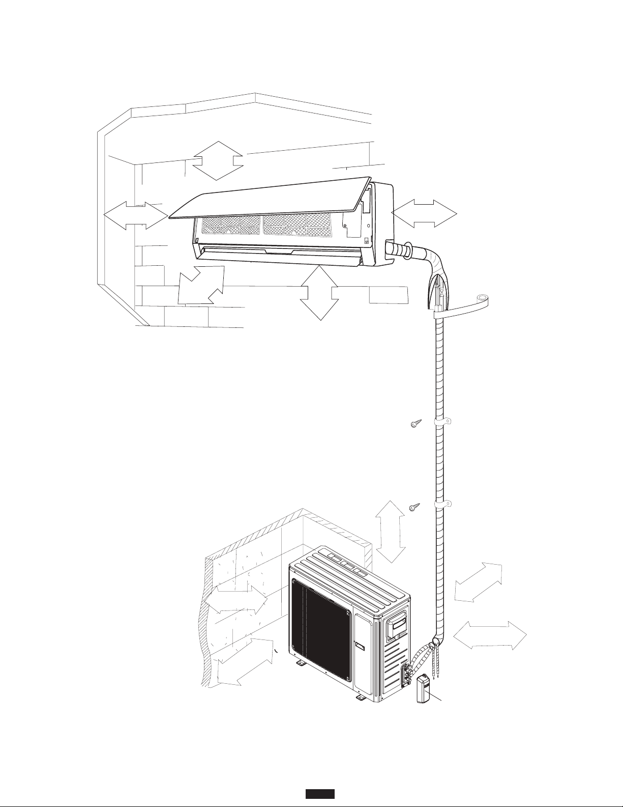
Typical Installation Setup ........................................................................................................... 7
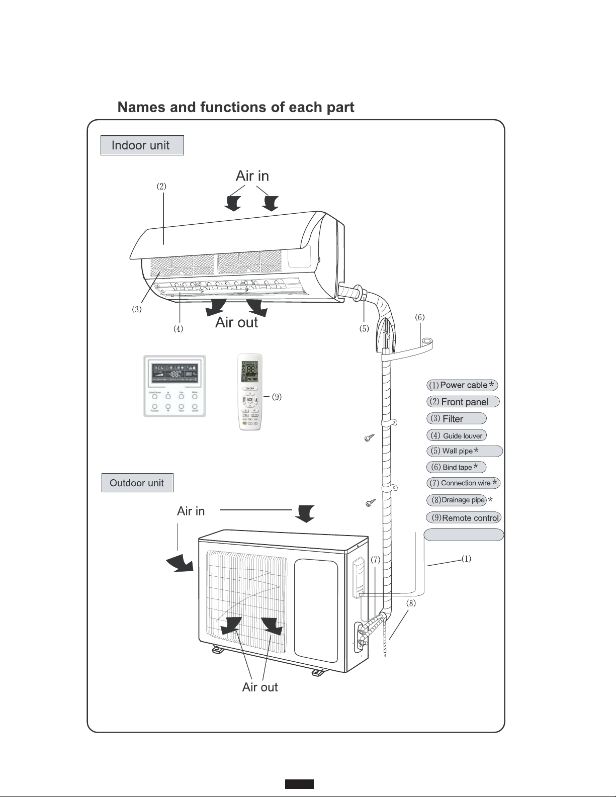
Names and Functions of Each Part........................................................................................... 7
Clearance Requirements........................................................................................................... 8
Connection Pipe Requirements................................................................................................. 9
Refrigerant Piping Precautions................................................................................................ 10
Nitrogen Purging While Brazing............................................................................................... 10
Installation Location................................................................................................................. 11
Installing the Indoor Unit.......................................................................................................... 12
Mounting Location ................................................................................................................... 12
Drilling the Piping Hole ............................................................................................................ 13
Refrigerant Piping at the Indoor Unit ....................................................................................... 13
Installing the Condensate Pipe................................................................................................ 15
Wiring at the Indoor Unit.......................................................................................................... 15
Binding the Pipes and Cables ................................................................................................. 17
Hanging the Indoor Unit........................................................................................................... 17
Installing the Outdoor Unit....................................................................................................... 18
Condensate Management of the Outdoor Unit........................................................................ 18
Installing the Refrigerant Piping............................................................................................... 19
Flaring Process and Bending Pipes ........................................................................................ 19
Refrigerant Piping at the Outdoor Unit .................................................................................... 20
Insulating the Pipe Joints......................................................................................................... 20
Piping Requirements ............................................................................................................... 21
Vacuum and Refrigerant Leakage Detection........................................................................... 22
Wiring Precautions .................................................................................................................. 23
Outdoor Wiring Connections ................................................................................................... 23
Stranded Wiring Connections.................................................................................................. 24
Electrical Connections............................................................................................................. 25
Cable Specifications ................................................................................................................ 26
Grounding Requirements ........................................................................................................ 26
Installation of Controllers......................................................................................................... 26
Post Installation Checklist........................................................................................................ 27
Test Operation ......................................................................................................................... 27
Refrigerant System Diagrams ................................................................................................. 28
Wiring Diagrams ...................................................................................................................... 29
Unit Dimensions ...................................................................................................................... 32
Common Error Codes............................................................................................................. 35
Emergency Operation.............................................................................................................. 35
Troubleshooting ....................................................................................................................... 36
Maintenance of the Indoor Unit ............................................................................................... 37
General Maintenance .............................................................................................................. 38

5
15 SEER Mini-Split
WARNING This mark indicates a potentially hazardous situation which, if not avoided,
could result in death or serious injury.
CAUTION
This mark indicates a potentially hazardous situation which, if not avoided,
could result in minor or moderate injury. It may also be used to alert against
unsafe practices.
NOTICE This mark indicates a situation which could result in equipment and/or
property damage.
Safety Precautions
Warnings, Cautions and Notices: Warnings, cautions and notices appear at appropriate intervals throughout
this manual. Warnings are provided to alert installing contractors to potential hazards that could result in
serious injury or death. Cautions are designed to alert personnel to conditions that could result in minor to
moderate injury. Notices alert to the possibility of equipment and/or property damage.
Your personal safety and the proper operation of this machine depend upon the strict observance of these
precautions.
WARNING
1. Installation should be left to the dealer or another professional. Improper installation may cause
water leakage, electrical shock or fire.
2. Install the air conditioner according to the instructions given in this manual. Incomplete installation
work may cause water leakage, electrical shock or fire.
3. Be sure to use the supplied or specified installation parts. Use of other parts may cause the unit to
come loose, resulting in water leakage, electrical shock or fire.
4. Install the air conditioner on a solid base that can support the weight of the unit. An inadequate
base or incomplete installation may cause injury or property damage in the event the unit falls off
of the base.
5. Electrical work should be carried out in accordance with the installation manual and local, state
and National Electric Code (NEC). Insufficient capacity or incomplete electrical work may cause
electrical shock or fire.
6. Be sure to use a dedicated power circuit. Never use a power supply shared by another appliance.
7. For wiring, use a cable that is long enough to cover the entire distance without splicing. Do not
use an extension cord. Do not put other loads on the power supply, use a dedicated power circuit.
(Failure to do so may cause abnormal heat, electric shock or fire.)
8. Use the specified types of wires for electrical connections between the indoor and outdoor units.
Firmly clamp the interconnecting wires so their terminals receive no external stresses. Incomplete
connections or clamping may cause terminal overheating or fire.
9. After connecting the interconnecting and supply wiring, be sure to shape the cables so that they
do not put undue force on the electrical covers or panels. Install covers over the wires. Incomplete
cover installation may cause terminal overheating, electrical shock or fire.
10. If any refrigerant has leaked out during the installation work, ventilate the room. (The refrigerant
produces a toxic gas if exposed to flames.)
11. When installing or relocating the system, be sure to keep the refrigerant circuit free from
substances other than the specified refrigerant (R410-A), such as air. (Any presence of air or
other foreign substances in the refrigerant circuit can cause an abnormal pressure rise or rupture,
resulting in injury.)

6
15 SEER Mini-Split
12. During pump-down, stop the compressor before removing the refrigerant piping. If the compressor
is still running and the stop valve is open during pump-down, air will be sucked in when the
refrigerant piping is removed, causing abnormal pressure in the refrigerant cycle which could lead
to breakage and injury.
13. During installation, attach the refrigerant piping securely before running the compressor. If the
compressor is not attached and the stop valve is open during pump-down, air will be sucked in
when the compressor is run, causing abnormal pressure in the refrigerant cycle which could lead
to breakage and injury.
14. Be sure to establish a ground. Do not ground the unit to a utility pipe, arrester, or telephone
ground. Incomplete ground may cause electrical shock, or fire. A high surge current from lightning
or other sources may cause damage to the air conditioner.
15. If the supply cord is damaged, it must be replaced by the manufacturer, its service agent or
similarly qualified persons in order to avoid electrical risk during and after replacement.
Pre-Installation Checklist
1. Unpack and inspect each unit.
2. Check for any damage to the unit.
3. Check the model numbers to ensure a proper match.
4. Check the unit nameplate to ensure the proper electrical requirements will be met.
5. Check the installation locations to ensure the weight of the units can be supported.
6. Check the line set size requirements to ensure the correct refrigerant lines have been run prior to
connection.
7. Check the electrical line requirements to ensure the proper wiring has been run prior to connection.
8. Check the indoor unit for coil leakage. The pressure relief valve on the gas line should release
pressurized nitrogen which ensures the unit has not leaked during shipping.
CAUTION
1. Do not install the air conditioner in a place where there is danger of exposure to flammable gas
leakage. If gas leaks and builds up around the unit, it may result in fire.
2. After all installation is complete, check to make sure that there is no refrigerant leakage.
3. This appliance is not intended for use by persons with a lack of experience and knowledge, unless
they have been given supervision or instruction concerning use of the appliance by a person
responsible for their safety.
4. Children should be supervised to ensure that they do not play with the appliance.
NOTICE
1. Establish drain piping according to the instructions in this manual. Inadequate piping may cause
flooding.
2. Tighten the flare nut according to the specified method such as with a torque wrench. If the flare
nut is tightened too hard, the flare nut may crack and cause refrigerant leakage.

(10)Wired controller
(10)
(Sold Separately)
* Field provided
1
7
15 SEER Mini-Split
Typical Installation Setup

8
15 SEER Mini-Split
valve cover
Space to the wall
Space to the ceiling
Space to the wall
Space to the wall
Air outlet side
Space to the floor
or more or more
6 in. or more 6 in. or more
12 in. or more
20 in. or more
20 in. or more
12 in. or more
or more.ni
97
or more
Space to the obstruction
Air outlet side
Space to the wall
Air inlet side
The dimensions of the space necessary for correct
installation of the appliance including the minimum
permissible distances to adjacent structures
6 in.
66
in.
118 in.
Clearance Requirements
NOTE:
The maximum recommended height from the floor to the bottom of the indoor unit is 11.5 ft. (3.5 m).

Operating Ranges
Connection Pipe Requirements
Cooling Operating Range Outdoor Temperature 0 - 115°F (-18 - 46.1°C)
Heating Operating Range Outdoor Temperature -4 - 75°F (-20 - 24°C)
Indoor Operating Range Indoor Temperature 61 - 86°F (16 - 30°C)
9
15 SEER Mini-Split
NOTICE
The maximum length of the connection pipe is listed in the table below. Do not place the units
such that the distance between them exceeds the maximum length of the connection pipe.
NOTES:
1. The connection pipe should be insulated with proper water-proof insulating material
2. Wall thickness of pipe 0.5-1.0 mm (0.02-0.04 in): bearing pressure 435 PSI (3.0 MPa)
3. Shorter connecting pipe lengths result in greater thermal efficiency, so it is preferable to reduce
connecting pipe lengths where possible.
4. See the oil trap instructions on page 21 for specific requirements when there is height
difference between the indoor and outdoor unit greater than 20 feet.
Heat Pump M4THS1509A M4THS1512A M4THS1518A M4THS1524A
M4MHW1509A M4MHW1512A M4MHW1518A M4MHW1524A
Refrigerant Charge (oz.) 24.7 30 49.4 65.3
Standard Length m (ft) 7.6 (25)
Additional Refrigerant Charge (oz/ft)
For Piping Beyond Standard Length 0.2 0.5
Outer Diameter Liquid Pipe mm (in) Φ6.35 (1/4")
Gas Pipe mm (in) Φ 9.52 (3/8") Φ12.7 (1/2") 15.875 (5/8")
Max Distance Height m (ft) 20 (65)
Length m (ft) 30 (100) 40 (130)
Minimum Piping Length m (ft) 3 (10)
Compressor Oil Used DAPHNE FVC50K (PVE Oil) RB68EP (POE Oil)
Cooling Only M4TCS1509A M4TCS1512A M4TCS1518A M4TCS1524A
M4MCW1509A M4MCW1512A M4MCW1518A M4MCW1524A
Refrigerant Charge (oz.) 24.7 30 35.3 56.4
Standard Length m (ft) 7.6 (25)
Additional Refrigerant Charge (oz/ft)
For Piping Beyond Standard Length 0.2
Outer Diameter Liquid Pipe mm (in) Φ6.35 (1/4")
Gas Pipe mm (in) Φ 9.52 (3/8") Φ12.7 (1/2") 15.875 (5/8")
Max Distance Height m (ft) 20 (65)
Length m (ft) 30 (100) 40 (130)
Minimum Piping Length m (ft) 3 (10)
Compressor Oil Used DAPHNE FVC50K (PVE Oil) RB68EP (POE Oil)

Refrigerant Piping Precautions
Nitrogen Purging While Brazing
10
15 SEER Mini-Split
WARNING
Hazard of Explosion and Deadly Gases!
Failure to follow all proper safe refrigerant handling practices could result in death or
serious injury. Never solder, braze or weld on refrigerant lines or any unit components
that are above atmospheric pressure or where refrigerant may be present. Always
remove refrigerant by following the guidelines established by the EPA Federal Clean
Air Act or other state or local codes as appropriate. After refrigerant removal, use dry
nitrogen to bring system back to atmospheric pressure before opening system for
repairs. Mixtures of refrigerants and air under pressure may become combustible in the
presence of an ignition source leading to an explosion. Excessive heat from soldering,
brazing or welding with refrigerant vapors present can form highly toxic gases and
extremely corrosive acids.
NOTICE
System Component Damage!
Do not remove the seal caps from the refrigerant connections and piping until prepared
to braze refrigerant lines to the connections. Excessive exposure to atmosphere (>5
min.) may allow moisture or dirt to contaminate the system, damaging valve seals and
causing ice formation in the system components during operation.
Nitrogen purging while brazing refrigerant pipes
Flow meter
Pressure regulator
Stop valve
Nitrogen
Nitrogen
NOTICE
Avoid Unit Damage!
Never braze pipe connections without performing nitrogen purging. Failure to perform
this procedure will damage the unit, resulting in capacity loss and reduced long-term
reliability.
While brazing refrigerant pipes, continuously purge them with nitrogen gas. Use a
pressure regulator to maintain a flow rate of 1.8 SCFH (0.85 LPM) or more.

WARNING
Adequate Support Required!
The wall structure must be adequate to support the weight of the unit. Failure to ensure
adequate structural support could result in the unit falling from its location which could
result in death, serious injury, or equipment or property damage.
11
15 SEER Mini-Split
1. Avoid locating the indoor unit where the return and/or supply air may be obstructed.
2. Select a location where it is easy to drain the condensing water and connect to the outdoor unit.
3. Keep the indoor unit far away from heat sources, vapor and flammable gas.
4. Be sure that the installation of the indoor unit conforms to the installation dimension diagram.
5. Be sure to leave enough space to allow access for routine maintenance; clearance between the
bottom of the indoor unit and the floor should not be less than 66".
6. Install in a location where the unit is more than 3 feet away from other electronic appliances that
could cause interferance, such as television, audio devices, etc.
7. Select a location where air filters can be easily removed and replaced.
Installation Location
Indoor Unit
Outdoor Unit
WARNING
1. Install the unit where it will not be tilted by more than 5°
2. If the location is subject to strong winds, the additional force must be accounted for and
the unit must be fixed securely to the base.
1. Select a location from which noise and air discharge are unobjectionable. Adhere to noise
ordinances that may be in place by the AHJ.
2. Select a location where there is sufficient ventilation.
3. Make sure the air inlet and outlet are not blocked by any obstacles.
4. Select a location capable of supporting the weight and vibration of the outdoor unit, and where
installation work can be carried out safely.
5. Select a location away from flammable gas or gas leaks.
6. Make sure that the installation of the outdoor unit conforms to the installation dimension diagram.
7. Locate the outdoor unit away from any bedroom windows.
NOTICE
Installing the unit in one of the following locations could result in unit malfunction:
1. Places where oil (machine oil) is used
2. Seaside places with high levels of salt in the air
3. Places with high levels of sulfur gas, such as areas with hot springs
4. Places where high-frequency waves are generated by radio equipment, welders and medical
equipment
5. Other unusual places where unit operation may be altered

Installing the Indoor Unit
12
15 SEER Mini-Split
WARNING
Hazardous Service Procedures!
The maintenance and troubleshooting procedures recommended in this section of the
manual could result in exposure to electrical, mechanical or other potential safety
hazards. Always refer to the safety warnings provided throughout this manual
concerning these procedures. Disconnect all electrical power including remote
disconnect and discharge all energy storing devices such as capacitors before
servicing. Follow proper lockout/tag out procedures to ensure the power can not be
inadvertently energized. When necessary to work with live electrical components, have
a qualified licensed electrician or other individual who has been trained in handling live
electrical components perform these tasks. Failure to follow all of the recommended
safety warnings provided, could result in death or serious injury.
Left
Wall
Φ2 3/16 inch
Right
Mark in the middle of it Level meter
Rear piping hole
Wall
Space
to the
wall
min.
6 inch
Space
to the
wall
min
6 inch
Φ2 3/16 inch
Rear piping hole
12K:09K:
Left
Wall
Φ2 3/16 inch
Right
Mark in the middle of it Level meter
Rear piping hole
Wall
Space
to the
wall
min.
6 inch
Space
to the
wall
min.
6 inch
Φ2 3/16 inch
Rear piping hole
Left
Wall
Φ2 3/4 inch
Right
Mark in the middle of it Level meter
Rear piping hole
Wall
Space
to the
wall
min.
6 inch
Space
to the
wall
min.
6 inch
Φ2 3/4 inch
Rear piping hole
24K:18K:
Left
Wall
Φ2 3/16 inch
Right
Mark in the middle of it Level meter
Rear piping hole
Wall
Space
to the
wall
min.
6 inches
Space
to the
wall
min.
6 inches
Φ2 3/16 inch
Rear piping hole
Mounting Location
1. Confirm the mounting location with the customer. Keep in mind the guidelines for a
safe installation location on page 11.
2. Place the wall-mounting frame on the wall and check that it is level. Mark the screw
holes to be drilled, ensuring they are in a place with adequate support.
3. Drill the holes on the wall according to the selected marks. If they are not drilled into
a solid backing, insert expanding plastic wall anchors to give added support.
4. Attach the wall-mounting frame with the supplied tapping screws and check to make
sure it is firmly attached. If any of the screws or anchors are loose, select another
point on the frame to re-drill and attach securely.
5. Be sure that the wall-mounting frame has been secured firmly enough to withstand
4 times the weight of the unit. The weight should be evenly shared at each fastening
point.

13
15 SEER Mini-Split
1. When the position of the drain piping has been selected, cut out the corresponding
knock-out from the unit housing.
2. Select the position of the piping hole to be drilled according to the direction of the
drain pipe position selected for the application. The position of the piping hole should
be slightly lower than the wall mounted frame.
3. Drill a hole with the diameter of 2 3/16 inch or 2 3/4 inch (24K unit) for the selected
outlet pipe position. In order to drain smoothly, slant the piping hole on the wall
slightly downward to the outdoor side with a gradient of 5-10°. (As shown below)
4. Insert a sleeve into the hole to prevent the connection piping and wiring from being
damaged when passing through the hole.
Drilling the Piping Hole
The piping can be connected in the direction of right, rear right, left or rear left.
Left
Rear left
Right
Rear right
Cut off
the hole
Left Right
Refrigerant Piping at the Indoor Unit
Detach the caps and plugs from the pipes.
NOTICE
1. Be sure to connect the pipe to the port on the indoor unit correctly. If the centering is
improper, the flare nut cannot be tightened smoothly. If the flare nut is forced to turn, the
threads will be damaged.
2. Do not remove the flare nut until the connection pipe is to be connected so as to prevent dust
and impurities from entering the piping system.
NOTICE
1. When a wall sleeve is not used, it is then necessary to drill a straight hole in the wall. If the
hole is not straight and uniform, this could result in water leaking from condensation resulting
in property damage.
2. If a wall sleeve is not mounted in the wall, the wiring between the indoor unit and the outdoor
unit can possibly be damaged resulting in electrical current loss in the ground wiring.
Indoor
5-10
outdoor
Φ55(2 3/16)
Φ70(2 3/4)
mm(inch)

In. (mm) Tightening Torque
1/4 (6.35) 15 ~ 20 N•m / 11.10-14.75 (ft-lbf)
3/8 (9.52) 30 ~ 40 N•m / 22.12-29.50 (ft-lbf)
1/2 (12.7) 45 ~ 55 N•m / 33.19-40.56 (ft-lbf)
5/8 (15.9) 60 ~ 65 N•m / 44.24-47.94 (ft-lbf)
3/4 (19.05) 70 ~ 75 N•m / 51.32-55.31 (ft-lbf)
14
15 SEER Mini-Split
Back-up Wrench
1. When connecting refrigerant pipe to the unit or removing it from the unit, please use both a
back-up wrench and the torque wrench. See illustration below.
2. When connecting, place oil on the backside of the copper tube flare prior to tightening. Do not
place oil on the flare face, as this will promote system contamination, tighten it by hand and
then tighten it with the spanner.
3. Refer to the torque reference table below before tightening to determine the appropriate torque
(too tight would damage the nut and lead to leakage).
4. Examine the connection pipe to see if it leaks, then apply the thermal insulation for the liquid
and gas lines, as shown below.
5. Use the medium-sized sponge wrap to insulate the connection point of the gas pipe.

15
15 SEER Mini-Split
Installing the Condensate Pipe
NOTICE
Do not wrench or bend the drain hose and make sure the ends of the condensate pipe are not
under water. Failure to do so could result in leakage.
Outlet
pipe
Drain hose
Drain hose
Tape
Outlet pipe
Drain hose
Insulating pip
e
1. Connect the drain hose to the outlet pipe of the indoor unit (as shown in Fig. A below).
2. Bind the joint with tape (as shown in Fig. B below).
3. Wrap the pipe with insulating tape to prevent condensation (as shown in Fig. C below).
Fig. A Fig. B Fig. C
Wiring at the Indoor Unit
1. Open the front panel of the indoor unit, remove the screw on the wiring cover and remove the
cover (as shown in Fig. D below).
2. Thread the power connection wire through the cable-cross hole at the back of the indoor unit
and pull it through to the front side (as shown in Fig. E below).
wiring cover
screw
panel
power connection
wire
cable-cross
hole
Fig. D Fig. E

16
15 SEER Mini-Split
3. Remove the wire clip and connect the power connection wire to the wiring terminal according
to the correct color coding. Using 4 wire colors (for example: Black, Blue, Red, Green) Connect
Black to 1, Blue to 2, Red to 3 and Green to Ground. All wiring shall use ring or spade type
crimped or soldered connectors to assure communication is not interrupted. (as shown on page
24). Tighten the screw then fix the power connection wire with the wire clip.
4. Put the wiring cover back on the unit and tighten the screw.
5. Close the front panel.
6. The primary disconnect for both the indoor and outdoor unit is to be wired to disconnect the
branch circuit feeding the outdoor unit. The Indoor unit obtains high voltage and communication
from the outdoor unit. If the AHJ (authority having jurisdiction) requires a branch circuit
disconnect before the indoor unit, then only break leg 1 and leg 3 between the indoor and
outdoor unit. Line 2 shall be a continuous wire with no splices between the indoor and outdoor
unit.
7. The system must be disconnected at the outdoor unit before performing service or
maintenance to avoid risk of electric shock or damage to equipment.
8. Terminal 2 carries communication signals and should not be cut or spliced.
9. The ground wire must connect directly from the outdoor unit to the indoor unit. To avoid
communication errors, do not connect the ground wire to the terminal block from any other
location.
Outdoor unit connection
09,12, 18, 24K models:
3
2
N(1)
green
green)
red
black
(yellow-
(brown)
white
(blue)
NOTE: The wiring diagrams in this guide are included as a reference. The manufacturer
has a policy of continuous product and product data improvement and reserves the
right to change design and specifications without notice. Always check the unit
nameplate and wiring diagram for the actual unit requirements.

17
15 SEER Mini-Split
Binding the Pipes and Cables
Note: The refrigeration lines shall be insulated separately to prevent heat transfer between the
two lines. Both lines shall be insulated.
1. Bind the insulated refrigerant pipes, power cord and drain hose with a band.
2. Reserve a length of drain hose and power cord for installation when binding them. Leave room
to separate the drain hose from the power and pipe connections for the outdoor unit.
3. Wrap them evenly.
4. The liquid pipe and gas pipe should be bound separately at the end.
5. When possible, keep the power cord and communication lines separated.
6. The drain hose should be bound at the bottom.
indoor unit gas
pipe
indoor and
outdoor power cord
liquid pipe
drain hose
band
drain hose
band
connection pipe
indoor power cord
Hanging the Indoor Unit
Note: It is recommended the indoor unit be mounted on a non-porous flat surface. Doing so will
reduce unfiltered air from entering the unit as well as reduce sweating behind the unit. Assure
the insulation sections surrounding the refrigeration and condensate line are sealed and without
cracks or openings.
1. Insert the bound pipes and wires into the wall sleeve and pass through to the outside.
2. Hang the indoor unit on the wall-mounting frame.
3. Stuff the gap between pipes and the wall hole or sleeve with sealing material.
4. Secure the wall pipe bundle with saddles.
5. Check if the indoor unit is installed securely and snugly to the wall.
6. Do not bend the drain hose too excessively in order to prevent blockage.
sleeve
upper hook
lower hook of
wall-mounting frame

When the outdoor unit is surrounded by walls or other obstructions, the installation space
of the unit should be no less than the clearances indicated below. For efficient operation,
leave three of four directions of peripheral constructions open when possible.
WARNING
1. Install the unit where it will not be tilted by more than 5°
2. If the location is subject to strong winds, the additional force must be accounted for and
the unit must be fixed securely to the base.
>20(500)
>39(1000)
>79(2000) >20 (500)
>20(500)
>20(500)
>79(2000)
inch(mm)
Installing the Outdoor Unit
Select the installation location that provides easy access to the indoor unit.
1. Make sure the location can support at least four times the weight of the unit.
2. Secure the outdoor unit on the selected base location with expansion screws.
3. The outdoor unit should be installed at least 1 1/16 inch above the ground or base in order
to install a drain joint (as shown below).
At least 1 1/6 inch clearance
Condensate Management of the Outdoor Unit
1. It is required to install a drain pipe for the outdoor unit to drain out the condensate water
during heating operation. Note: In climates where outdoor freezing is an issue, the pipe and
connection should be adequately protected from freezing. (Self-regulating heat tape is one
example of pipe freeze protection).
2. When installing the drain pipe, apart from the drain pipe mounting hole, all other holes should
be plugged so as to avoid water leakage.
3. Insert the drain pipe fitting into the drain pipe mounting hole located at the base of the unit and
then connect the drain pipe to the pipe joint.
18
15 SEER Mini-Split

1. Place the outdoor unit on the support base.
2. Secure the foot holes of the outdoor unit with bolts (as shown below).
Foot holes
Foot holes
Installing the Refrigerant Piping
Flaring Process
1. Hold the pipe downward to prevent cuttings from entering the pipe.
2. Cut the refrigerant pipe with the pipe cutter and remove the burrs.
3. Remove the flare nuts at the stop valve of the outdoor unit and inside the accessory bag of the
indoor unit, put them onto the refrigerant pipe as shown below then flare the refrigerant pipe
with a flaring tool.
4. Check if the flare part is spread evenly and there are no cracks.
Bending Pipes
1. The pipes should be shaped by your hands or a refrigerant pipe bending tool for tighter bends.
Be careful not to collapse them.
2. Do not bend the pipes in an angle more than 90°.
3. When pipes are repeatedly bent or stretched, the material will be prone to damage, which may
lead to refrigerant leaks. Do not bend or stretch the pipes more than three times.
19
15 SEER Mini-Split

NOTICE
1. To prevent distortion and breaking of the pipe, avoid sharp bends. Bend the pipe with a radius
of curvature of 6 in. (150 mm) or more.
2. If the pipe is bent repeatedly at the same place, it will break.
CAUTION
Be sure to connect the gas pipe after connecting the liquid pipe completely.
Refrigerant Piping at the Outdoor Unit
Tighten the flare nut of the connection pipe at the outdoor unit valve connector. The tightening
method is the same as the method at the indoor unit.
Insulating the Pipe Joints
1. All refrigerant piping should be insulated with appropriate insulating material and
plastic tape in order to prevent condensation and water leakage.
2. The joints of the indoor unit should be wrapped with insulating material. No gap is
allowed on the joint of the indoor unit, as shown below.
4. Do not bend the pipe while it is encased in the insulation. In this case, cut the insulation with a
sharp cutting tool as shown below, and bend it after exposing the pipe. After bending is complete,
assure the insulation wrapping is sealed.
20
15 SEER Mini-Split
Other manuals for M4MHW15-A
1
This manual suits for next models
3
Table of contents
Other Ameristar Air Conditioner manuals