Eaton YHPTZ41 Series User manual

Instruction Manual
YHPTZ41 Series
Explosion proof Integrated Camera Set
IP Code: IP 68 (1.2m/45min)
Ex Marking:
II2G Ex db op is IIC T6 Gb (for type YHPTZ41)
or Ex db IIC T6 Gb (for type YPTZ41-1)
II2D Ex tb IIIC T80°C Db
Ex tb op pr IIIC T95°C Db (optical fiber version)
Certificate number: 0470 Presafe 14 ATEX 4570X

2eaton www.eaton.com
Copyright Statement
Cooper Yuhua (Changzhou) Electric Equipment Manufacturing Co.,
Ltd (hereinafter referenced as Cooper Yuhua). Claims copyright
ownership of the contents (including text and images) of this
Instruction Manual. Any content may not be copied, transferred,
modified or reproduced by any person or organization without
expressed permission of Cooper Yuhua.
Cooper Yuhua remains the right to modify the content and
technical specifications of the product in this Instruction Manual
without any form of notification, in order to provide the newest
and most advanced product. The end users can get the latest
product information on Yuhua’s website: http://www.cyh.com.cn.
Trademark statement
This is the trademark of Cooper Yuhua (Changzhou) Electric
Equipment Manufacturing Co., Ltd., all right reversed. The other
trademark and trademark right appeared in this Instruction Manual
belongs to its legal holder.

3eaton www.eaton.com
Quality Guarantee
For YHPTZ41 explosion-proof integrated camera set, we provide
free maintain service in the guarantee period but we will ask the
user to pay for the cost of labor and component in the follow
conditions:
• Damage caused by improper operation that against the
Instruction Manual.
• Damage caused by unauthorized disassembly.
• Thunder or other force majeure natural disasters.
If any other contracts between clients and us exist, we will follow
the promise or regulation strictly.
Security Assurance
Operation of this product fulfills the following two requirements:
• No adverse interference in operation;
• The operation of this product can not be interfered by external
factors even adverse interference.

4eaton www.eaton.com
Notice
• The user shall not disassemble this product optionally, such
as remove the top cover or bolts may cause leakage of water
or electricity. Please operate the product according to the
requirements in this Instruction Manual;
• Ensure this product is always used in environment with
atmosphere pressure, ambient temperature and relative
humidity specified in Chapter 1.6;
• To be sure the power supply comply with the requirement
indicated in the nameplate;
• The internal and external grounding shall be reliable;
• Ensure the installation is firm and reliable, to avoid unexpected
damage of the camera;
• Protect the flame-proof joints from stumble and crack in
installation, operation and maintenance.
Thank you for selecting Cooper Yuhua product!
Please read this Instruction Manual carefully before
Installation, operation and maintenance of this product and
follow the manual. Please keep this manual properly.

5eaton www.eaton.com
Content
Copyright Statement........................................................................................................................... 2
Trademark statement .......................................................................................................................... 2
Quality Guarantee ............................................................................................................................... 3
Security Assurance.............................................................................................................................. 3
Notice ................................................................................................................................................... 4
Ex structure instruction ...................................................................................................................... 7
Correct method to move YHPTZ41 .................................................................................................... 7
1.0 General ........................................................................................................................................... 8
1.1 Type and model .......................................................................................................................... 8
1.2 Features ..................................................................................................................................... 9
1.3 Scope ......................................................................................................................................... 9
1.4 Mechanical data ......................................................................................................................... 9
1.5 Electrical data............................................................................................................................. 9
1.6 Service condition ....................................................................................................................... 9
1.7 Electrical safeties (standard atmospheric pressure) .................................................................. 9
2.0 Installation & debugging............................................................................................................ 10
2.1 Cautions................................................................................................................................... 10
2.2 Assembly .................................................................................................................................11
2.3 Usage ...................................................................................................................................... 12
2.4 Support preparation before installation of YHPTZ41 ............................................................... 14
2.5 Installation and fastening......................................................................................................... 15
2.6 Protection of flame-proof joint................................................................................................. 15
2.7 Grounding................................................................................................................................ 15
2.8 Reserved cable........................................................................................................................ 15
2.9 Camera Time settings.............................................................................................................. 15
3.0 Troubleshooting........................................................................................................................... 15
4.0 Transportation and storage ........................................................................................................ 16
4.1 Cautions in hoisting and transportation................................................................................... 16
4.2 Storage condition, duration and cautions................................................................................ 16
5.0 Camera specifications ................................................................................................................. 16
Annex 1: Table of poisonous and harmful substances or elements............................................. 17

6
Instruction Manual
Effective March 2020
eaton www.eaton.com
Safty Requirement
Please read this Instruction Manual carefully before
installation and operation of this product.
1. Safety cautions in installation
• Cut off the power supply before any maintenance or repair of
the product.
• Avoid opening of this product in environment where oil smoke,
heavy dust, high temperature or dewing may exist. These will
cause the decrease of the image definition.
• Connect the cables according to the requirement indicated in
the Instruction Manual, or fault may happen.
• Protect the flame proof joint in maintenance; avoid any metal
fragment or other substances get access in the internal chamber.
• No disassembly or modification allowed.
2. Construction Safety
• The protective regulations on construction spot shall be
followed strictly.
• Measurement shall be carried out immediately when any security
risks found to eliminate the risks, stop construction if necessary.
• All kinds of safety facilities shall be inspected, calibrated or
repaired in the event of severe weather.
• The ice, fog, rain and snow shall be removed before opening.
• Alert area shall be set and a person shall protect the area
when protective casing and other safety facilities are
constructed or dismantled.
• Work high above the ground may require in installation of this
product, the operating personnel shall be qualified.
3. Power supply requirements
• Local electrical safety standard shall be followed in installation
and service of this product.
• Convenient de-energizing device shall be adopted for
immergence cutting off.
• Check if the power supply is suitable for operation before start.
• Protect the power cable from trample or compressing,
especially for the plug, socket and joint out from devices.
• Explosion-proof measurement is necessary for Ex products.
4. Service condition requirements
• Please do not focus the camera to hard light (such as lamp or
sunlight), which will cause too bright of the image, it will not
malfunction but it will affect the operational life of the CCD
(or CMOS).
• Transport, operate and store this product in applicable
temperature and humidity range. Do not locate it in wet,
overheated (over +60°C), extreme cold (less than -30°C)
environment or area with strong electromagnetic radiation or
power lighting conditions.
• The product shall be protected from any entry of water
or other conductive fluid, which may damage the internal
electrical element.
• Avoid overheated, the product shall be well ventilated.
• Avoid damage caused by compressing or violent vibration in
transmission, storage or operation.
• The product shall be well packaged as new product or
equivalent in transmission.
• We suggest using this product with Surge Protection Devices.
• Internal and external grounding shall be reliable.
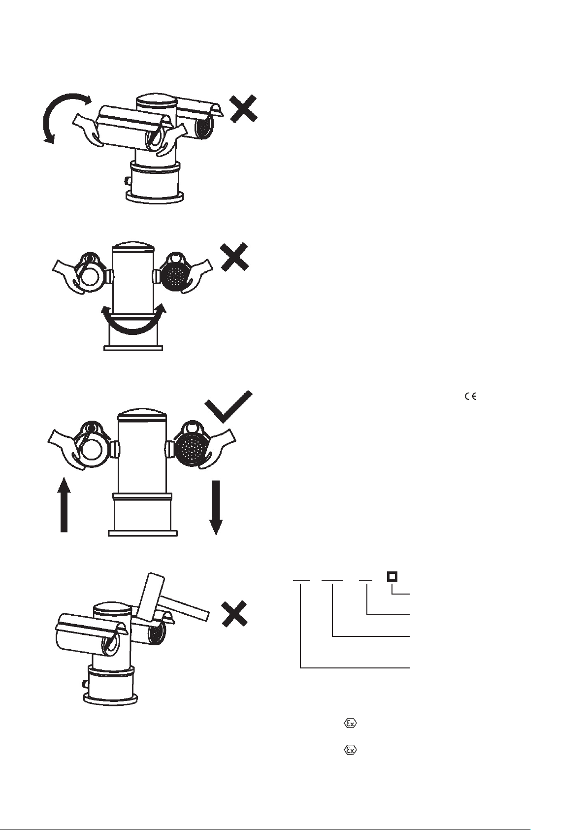
5. Operation & maintenance requirements
• Do not dismantle this product; there is no user serviceable
part inside.
• Do not touch the CCD (or COMS) directly; a proper way
is to blow away the dust with a blower on the lens. If it is
necessary to clean it, use soft cloth with a little alcohol to
wipe the lens gently. Replace the cover when not use to
protect the CCD (or COMS).
• Soft, dry cloth can be used for camera body cleaning. For dirt
not easy to clean, some neutral detergent can be used, clear
the dirt away then dry the camera body. Corrosive agent,
abrasive cleaner can not be used for camera cleaning; they may
damage the surface or even degree the service performance.
• This product shall be installed and repaired by authorized
personnel, please do not dismantle or repair it by yourself. Only
manufacturer indicated components / accessories can be used
when replacement is necessary.
• The CCD (or COMS) may damage by laser beam, it’s better to
avoid the camera suffering radiation of laser beam.
6. Environmental protection
• For components of the products made by our company may
pollute the environment, such as PCB, electrical elements,
plastic and lubricant, collection and control measurement
shall be taken in maintenance and scrapping of the products.
These pollution sources shall be delivered to the government
for further treatment, no casually discard allowed, avoid any
adversative effect to the environment.
Special announcement
• Some pictures in this manual is a diagram for reference only,
if the picture does not match with the real product, the real
product is the standard.
• Cooper Yuhua remains the right to modify the content and
technical specifications of the product in this Instruction Manual
without any form of notification when the product updates,
there may exist little differences after updating.
• You can get the latest software and description document by
consulting the customer service department.
• Any problem in operation of this product, please contact the
distributor or customer service department.
• We always try to make this instruction manual as perfect as
we can, but there still may be some de-tolerance between the
real data and the data we provide, if you have any questions or
disputes, please refer to our company for finally explanation.
• The operator or user shall be responsible for damages or
losses caused by misuse or operations do not comply with
this manual.

7
Instruction Manual
Effective March 2020
eaton www.eaton.com
Ex structure instruction
• The enclosure is able to subjected to static pressure test
(1.5MPa for at least 10s) specified in GB3836.2/ IEC60079-
1:2014/ EN60079-1:2014, no leakage or deformation allowed
after test.
• The maximum surface temperature will no more than 80°C in
normal operation.
• Toughed glass is adopted in observation port, it has passed the
impact and thermal shock test.
• IP68 (1.2m/45min);
• Stuffing box type cable entries are adopted in this product, the
reserved length of the cable is no less than 2 meters.
Serrated joint
Serrated joint
Serrated joint
Spigot joints
Correct method to move YHPTZ41
When the product is not energized
Select the best position to move the product
Vertical cylinder part free rotation
Horizontal cylinder part free rotation
No knocking down

8
Instruction Manual
Effective March 2020
eaton www.eaton.com
When the product is energized
Vertical cylinder part can not rotate freely
Horizontal cylinder part can not rotate freely
The product can not be moved freely
No knocking down
1.0 General
YHPTZ41 series explosion-proof integrated camera set
is manufactured according to GB3836.1-2010 Explosive
atmospheres–Part 1 Equipment– General requirements,
GB3836.2-2010 Explosive atmospheres – Part 2: Equipment
protection by flameproof enclosures “d”, GB12476.1-2013
Electrical apparatus for use in the presence of combustible
dust—Part 1-1: Electrical apparatus protected by enclosures
and surface temperature limitation—Specification for apparatus,
EN60079-0:2012/A11:2013 Electrical apparatus for explosive
atmosphere Part 0: General requirements, EN60079-1:2014
Electrical apparatus for explosive atmosphere Part 1: Flameproof
enclosure‘d’,EN60079-31:2014 Explosive atmospheres – Part
31: Equipment dust ignition protection by enclosure “tb”, EN
60079-28:2015 Explosive atmospheres - Part 28: Protection of
equipment and transmission systems using optical radiation,
IEC60079-0:2012 Explosive atmospheres - Part 0: Equipment -
General requirements, IEC60079-1:2014 Explosive atmospheres
- Part 1: Equipment protection by flameproof enclosures “d”,
IEC60079-31:2013 Explosive atmospheres –Part 31: Equipment
dust ignition protection by enclosure “t”,IEC 60079-28:2015
Explosive atmospheres - Part 28: Protection of equipment and
transmission systems using optical radiation. It is used in the
places, where is classified as Zone 1 and Zone 2, contained Group
IIA, Group IIB and Group IIC gases, temperature group T1~T6,
Zone 21 and Zone 22, contained the combustible dust atmosphere
or the mixture circumstance with the explosive gas atmospheres
and the combustible dust atmospheres. The product with the
characteristics of small volume, light weight, easy installation
and etc.. It can be used in petroleum, chemical, jetty, port, mine,
spaceflight, war industry and foodstuff process area and etc.
All associate technical document, drawings and samples of
YHPTZ41 series explosion-proof integrated camera are tested and
certified by Presafe, ATEX certification number: 0470 Presafe
14 ATEX 4570X
Specifc Conditions of Use
• Repairs of the flameproof joints must be made in compliance
with the structural specifications provided by the manufacturer.
Repairs must not be made on the basis of values specified in
tables 3 and 4 of EN 60079-1.
• The protect the cement joint, the glass clamp ring ie not
allowed to be opened from the infrared light cylinder.
Essential Health and Safety Requirements
Essential Health and Safety Requirements (EHSRs) are covered by
the standards listed at item 9.
1.1 Type and model
Explanation
Blank: with infrared light / -1:
with no infrared light
Design code
Ex product code, PTZ stands
for Ex-proof Integrated Camera.
Company code
YH PTZ 41 □
Model: YHPTZ41, YHPTZ41-1
IP Code: IP68 (1.2m/45min)
Ex marking:
II2G Ex db op is II C T6 Gb (for type YHPTZ41)
or Ex db IIC T6 Gb (for type YPTZ41-1)
II2D Ex tb IIIC T80°C Db

9
Instruction Manual
Effective March 2020
eaton www.eaton.com
1.2 Features
YHPTZ41 series explosion-proof integrated camera set integrates
high-performance color camera, omni bearing variable speed PTZ,
multifunction decoder controller and infrared light source, and
also common communication protocols and speed. It will give you
clear and bright images even in low-light conditions, it plays an
important role in security system.
YHPTZ41can work at wide voltage range and its self-adaptation
function will satisfy most brands of the video camera. It has
power supply, signal and video triple protection against lighting,
safe and reliable.
YHPTZ41 is designed as a integrated unit, it can continuously
rotate 360° horizontally and rotate to ±90° vertically with no
external cable between the PTZ and the camera. A sun shade, rain
wiper and heating devices are equipped with the product.
1.3 Scope
This product is applicable for Zone 1 and Zone 2 hazardous areas
that explosive mixture of group IIA, IIB, IIC, T1~T4 gases, vapor
and air may exists, Zone 21 and Zone 22 hazardous areas that
explosive dust may exist and hazardous areas that both the
explosive dust and gas mentioned above exist.
1.4 Mechanical data
Material: stainless steel 304 or 316L
Horizontal rotating range: CC 0~360°continues
Vertical rotating range: - 90 ~ + 90°
Horizontal rotating speed: 0.1° ~ 40° /S Smooth variable
speed rotation
Vertical rotating speed: 0.1° ~ 40° /S Smooth variable
speed rotation
Preset position speed: 60° /S
Preset position number(s): 128
Preset position precision: ≤0.1 °
Lighting Protection: Built-in lighting protection device
Automatic heating: Starts below -10°C
Infrared light range: Approximately 100 meters
Unit weight: 35kg (net weight)
Package weight: 38kg (gross weight)
Installation method: Vertical
Front view Side view
Figure 1.4.1.1 Dimensions
1.5 Electrical data
Input voltage:
Frequency:
100~240VAC
50~60Hz
Maximum current: ≤1A
Consumption: ≤100W
Electrical connection: Cable of 3 meters
PTZ control & communication
method:
RS-485
PTZ control & communication speed: 2400, 4800, 9600, 19200bps
(default: 4800bps)
PTZ control & communication
protocol:
PELCO-P, PELCO-D, VICON
(default: PELCO-D)
Address code: 0~255(default: 1)
1.6 Service condition
Atmospheric pressure 80~110KPa
Ambient temperature -40°C~+60°C
Relative humidity ≤95%RH(+25°C)
1.7 Electrical safeties (standard atmospheric pressure)
Insulation resistor: at voltage of DC500V, the resistor between the
power in terminals and the enclosure is no less than 100 MΩ;
Voltage withstand test: adopt voltage of 1500V, 50Hz at the power
in terminals and the enclosure for 1 minute, no break down or arc.

10
Instruction Manual
Effective March 2020
eaton www.eaton.com
2.0 Installation & debugging
2.1 Cautions
Check the component in the package before installation
YHPTZ41 mainframe 1 set
Sun shade 2pcs
Certificate of conformity, Qualification certificate and Instruction Manual
Cross recess oval head screws: M5X8 4pcs
Hexagon bolts: M8X30 6pcs
Brass screws:1/4”X6 1pc
Brass screws:1/4”X12 1pc
Special adjustable wrench 1pcs
干
燥
剂
Drying agent: 1 package
特种润滑脂
Aluminum tube-loaded Teco521 grease: 1pc
Other tools required:
Cross screw driver: 6X150 1pc
Outer hexagon adjustable wrench: 300X36 1pc

11
Instruction Manual
Effective March 2020
eaton www.eaton.com
Cautions before installation and in service
Check the following items before installation:
a. Check if there is a certificate of conformity number
b. Check if the application area indicated in the Ex making is
suitable for the intend location
c. Check if there is any crack or other defect that may
damage the Ex performance
d. Check if there are internal and external grounding
Cautions in service:
a. It’s not suggested for users to dismantle this product at
will, please follow the Instruction.
b. The power must comply with requirements specified in 5.
c. Please use this product in conditions (atmosphere pressure,
temperature and humidity) specified in chapter 1.6.
d. Since Ex product is very special, debugging with power
before installation if available.
e. DO NOT OPEN WHEN ENERGIZED!
f. The yield stress of the fastener elements of each part
of the flame proof enclosure must be at least equal to
700 N/mm2.
2.2 Assembly
2.2.1 Component assembling
Fixing bolts of the sun shade: Cross
recess oval head screws: 4-M5X8
Figure 2.2.1.1 installation of sun shade
Caution: tighten the
compression nuts with
wrench after the cable or
flexible pipe are installed.
Figure 2.2.1.2 Tighten the compression nuts

12
Instruction Manual
Effective March 2020
EATON www.eaton.com
2.2.2 Cable treatment
• Cable treatment on finished products
• Please pay attention to the protection of the cable when using
Screw nut
base
Sealing
ring
washer
Rubber
gasket
washerFlat
gasket
Flame proof
seal fitting
HPS89-01
Epoxy resin
Bakelite
gasket
Lead-out
cable
Filling with A.B type cable sealing filler
Compression
nut
2.3 Usage
2.3.1 System connection
Figure 2.3.1.1 Connection diagram of the system
Digital video signal is transmitted by wired or wireless IP networks. The video can be monitored and recorded at any time, no matter in
LAN or WAN, such as internet.
2.3.2 Cable indication
A composite cable was equipped with finished product of YHPTZ41, it leads out from the side of the base-frame and its length is over 2
meters. The user shall lead the composite cable into the junction box and connected the system bus before service.
Table 2.3.2.1 Cable indication
Composite cable
Product Power cable UTP5E
Function Live wire Zero line Earth line Data transmission
Color brown Grey Yellow
/green
Orange
&
white
orange
green
&
white
blue
blue
&
white
green
brown
&
white
brown

13
Instruction Manual
Effective March 2020
eaton www.eaton.com
2.3.3 Parameter setting
Protect the joint Top cover
Set the communication
protocol, baud rate and
address here.
Figure 2.3.3.1. Parameter setting
Parameter setting method: use the special wrench to open the top
cover, set the communication protocol, baud rate and address by
using SW1, SW3, SW4, SW5, SW6 on the PCB.
Table 2.3.3.1. Definitions of SW1
SW1 Definitions
DIP 1~3 Model setting of RS-232 method controlled camera (see table 2.3.3.2)
DIP 5 PELCO_P/PELCO_D Protocol setting (see table 2.3.3.3)
DIP 6~7 Baud rate setting(see table 2.3.3.4)
DIP 8 Remote control switch(ON/OFF)
Function
setting
SW4
SW5
CPU RS485communication module
SW1
Address
setting
SW3
Figure 2.3.3.2 the main function switch arrangement on
the panel
2.3.3.1 Settings of SW1
Confirm the communication protocol and baud rate adopted by
the controller, then modify the settings according to the table as
below, at last restart or reboot remotely.
Figure 2.3.3.3 function switch SW1
• Protocol setting
PELCO-P, PELCO-D, VICON protocols can be used. PELCO-P and
PELCO-D protocol can be set directly by SW1. For VICON protocol,
the following instructions shall be followed: turn on the 8th switch,
which means start remote control, restart or reboot remotely after
setting; then adjust the baud rate, protocol and address according
to the indication; use 95# preset bit to enter <control> menu and
<RS485>sub menu, set the protocol to VICON protocol.
Table 2.3.3.3. Protocol setting
Protocol DIP 5 DIP 8
PELCO_P ON OFF
PELCO_D OFF OFF
VICON —ON
• Baud rate setting
Table 2.3.3.4. Baud rate setting
Baud rate DIP 6 DIP 7
2400 bps OFF OFF
4800 bps ON OFF
9600 bps OFF ON
19200 bps ON ON
2.3.3.2 Address setting (SW3, SW4, SW5)
Decimal encoding scheme is adopted in this product: hundred’s
digit(SW4), ten’s digit(SW5) and unit’s digit(SW3); address
range:0~255. The address is usually set on finished products, if
adjustment required, modify the settings then restart or reboot the
unit remotely to make the modification validate.
Eg. If the address of the explosion-proof integrated camera is 64:
set Sw4 at 0, SW5 at 6, SW3 at 4.
SW4 SW5 SW3
Figure 2.3.3.4 hundred’s digit(SW4), ten’s digit(SW5) and unit’s
digit(SW3)

14
Instruction Manual
Effective March 2020
eaton www.eaton.com
2.3.4 Infrared light setting
This product can provide distinct images in environment with
illuminance less than 0.5LUX, the user can select the illuminance
of the infrared light according to the environment.
This operation can achieved by S2 in the infrared light cylinder.
Infrared light control module
On/off the
illuminance
setting of
the infrared
light
S2
Figure 2.3.4.1. Connection of the camera and control meth-
od setting
Figure 2. Figure 2.3.5.1 Infrared light control switch
The switch ON and OFF of every digit in the infrared light control
switch is in correspondence with power on and power off of the
corresponding illuminance switch. The infrared light start to work
when the environment illuminance is lower than the set value of
the swith; it will stop work when the environment illuminance is
better than the set value.
The default setting is the 3rd digit is set on. Only one digit in S2
can be set at on and the others must be off. Restart or remotely
reboot is required for the changed setting.
Table 3.2.5.2. Definition of S2
DIP START-UP (LUX) SHUT-DOWN (LUX)
10.5 4
21.5 8
35 (Default) 20
410 50
515 75
620 100
7OFF OFF
8OFF OFF
2.3.5 Inspection and examination before service
Check if the power supply, AB control cable and video cable are
well connected and if the settings on the switch are correct.
2.3.6 Service status and inspection in service
YHPTZ41 will start self checking automatically after power on.
• Normal self checking procedures:
Rain wiper
run once
Horizontal left rotating a round→right
rotating a round
Vertical rotating to-90°→up to +90°→back
to horizontal position
2.3.7 Screen OSD display and menu setting
YHPTZ41 possess a perfect Chinese and English menu system:
via 95# preset position to callout the menu when the product is
stand by, the up, down, left and right button on the PTZ, also the
open and close button on the iris become control keys. At this
time, command of the other keys are invalid, all settings in the
menu can be saved when power cut off suddenly.
2.3.8 Camera setting, IE browser and client software setting
See document provided by the manufacturer of the camera.
2.4 Support preparation before installation of YHPTZ41
2.4.1 Support type installation
Select suitable position for installation hole, adopt expansion
anchors to fix the support. The Ex junction box shall be installed in
a place convenient for installation and maintenance. Laying down
the cable from the slot or tray to the junction box.
See 2.4.1.2 for the support specifications.
Install support
Slot or tray
Ex junction box
wall
Figure 2.4.1.1 Support installation and wire connection

15
Instruction Manual
Effective March 2020
EATON www.eaton.com
2.5 Installation and fastening
Since Ex product is very special, we strongly suggest that the user
to install this product after debugging and adjusting and familiar
with the performance indoor.
2.5.1 Support type installation
The installation hole see 2.4.1.2, insert the reserved cable into the
hole on the support. The cable shall be protected by Ex flexible
pipe when connect to junction box(armored cable is available).
The cable from junction box to control room shall be protected by
metal tube or adopt armored cable directly.
YHPTZ41
Cable slot to
control room
Figure 2.5.1.1 YHPTZ41(Ex) support installation
2.6 Protection of flame-proof joint
Protect the flame proof joint in installation, operation, maintenance
of this product, no knock or crack allowed.
Repairs of the flameproof joints must be made in compliance with
the structural specifications provided by the manufacturer. Repairs
must not be made on the basis of values specified in tables 2 of
EN/IEC 60079-1.
2.7 Grounding
Internal and external grounding shall be well connected and reliable.
2.8 Reserved cable
The length of cable reserved on finished camera is no less than
two meters, free end of the cable shall be located in associate Ex
terminal boxes or devices that suitable for the hazardous area.
2.9 Camera Time settings
During product use, the camera needs to reset the time after each
power outage restart.
3.0 Troubleshooting
phenomenon analysis solution
No image Power cut off Check the power supply
Network cable malfunction Check the network cable
Image
intermittence Network cable malfunction Check the network cable
Abnormal control
of PTZ
Network cable not well
connected Check the network cable
Communication distance too
long caused signal attenuation
Add repeaters to extend the
communication distance
Signal reflection
Short circuit the 120 wire
jumper (or switch) of the
farthest camera in the bus, add
a resistor of 120Ω to eliminate
the reflection
incorrect address
Set according to manualIncorrect protocol
Incorrect baud rate
Uncontrolled
camera Network cable malfunction Check the network cable

16
Instruction Manual
Effective March 2020
eaton www.eaton.com
4.0 Transportation and storage
4.1 Cautions in hoisting and transportation
Packaged product can be delivered in all modes of transportation
but without direct rain or snow.
4.2 Storage condition, duration and cautions
This product can be stored for one year in environment of
temperature range: 0°C~+40°C and humidity no more than 90%.
5.0 Camera specications
Camera Size Range:≤142*78*81(Length*Width*Height)
Rated voltage:12V±10%
Dissipation power:≤10W

17
Instruction Manual
Effective March 2020
eaton www.eaton.com
Annex 1:Table of poisonous and harmful substances or elements
Component
Poisonous and harmful substances or elements
Lead
(Pb) Mercury
(Hg) cadmium
(Cd) chromium VI
(Cr6+) Polybromide
(PPB) Polybrominated diphenyl
ethers (PBDE)
Stainless steel 304 ○ ○ ○ ○ ○ ○
Casting component ○ ○ ○ ○ ○ ○
PCB ○ ○ ○ ○ ○ ○
Movement ○ ○ ○ ○ ○ ○
Connection cable ○ ○ ○ ○ ○ ○
Power supply
(if applicable) ○ ○ ○ ○ ○ ○
Support
(if applicable) ○ ○ ○ ○ ○ ○
Accessories ○ ○ ○ ○ ○ ○
Remark:
1. Symbol ○means the content of the poisonous, harmful substances or elements in the component (homogeneous material) is
lower than the limit specified in the standard;
2. Symbol × means the content of the poisonous, harmful substances or elements in the component (some certain homogeneous
material) is more than the limit specified in the standard SJ/T11363-2006. Leakage or mutation of this poisonous, harmful
substances or elements will not happen in the environmental life and will not harm the user’s health or properties. Treatment
of this poisonous, harmful substances or elements can not carried out by user selves, please deliver it to the appointed
department according to the local laws or regulation.

Eaton
No.60 Hehuan Rd, Zhonglou Development
Zone, Changzhou, Jiangsu, China.
Tel: 0519-83900389, 83900558ZIP
code: 213023
Fax: 0519-83978970
Website: http://www.cyh.com.cn
© 2020 Eaton
All Rights Reserved
Printed in XXX
Publication No. TDXXXXXXXXE / XXXX
Article No. XXXXXX
March 2020
Eaton is a registered trademark.
All other trademarks are property
of their respective owners.
Changes to the products, to the information
contained in this document, and to prices
are reserved; so are errors and omissions.
Only order confirmations and technical
documentation by Eaton is binding. Photos
and pictures also do not warrant a specific
layout or functionality. Their use in whatever
form is subject to prior approval by Eaton.
The same applies to Trademarks (especially
Eaton, Moeller, and Cutler-Hammer). The
Terms and Conditions of Eaton apply, as
referenced on Eaton Internet pages and
Eaton order confirmations.
CONFIDENTIAL —
For internal use only by Eaton and
authorized distributors.
This information is intended to provide a
comparative analysis between Eaton’s
products and those of other manufacturers
based on the similarities and dissimilarities
between product offerings. It is not intended
to replace specific product literature for
Eaton products. Information contained in this
literature about other manufacturers’ product
is from written material and/or published, or
made available by the manufacturers.
This manual suits for next models
1
Table of contents