Sliding Keyboard/Pedestal Bracket
Instruction Sheet
IL211024EN
Effective May 2018
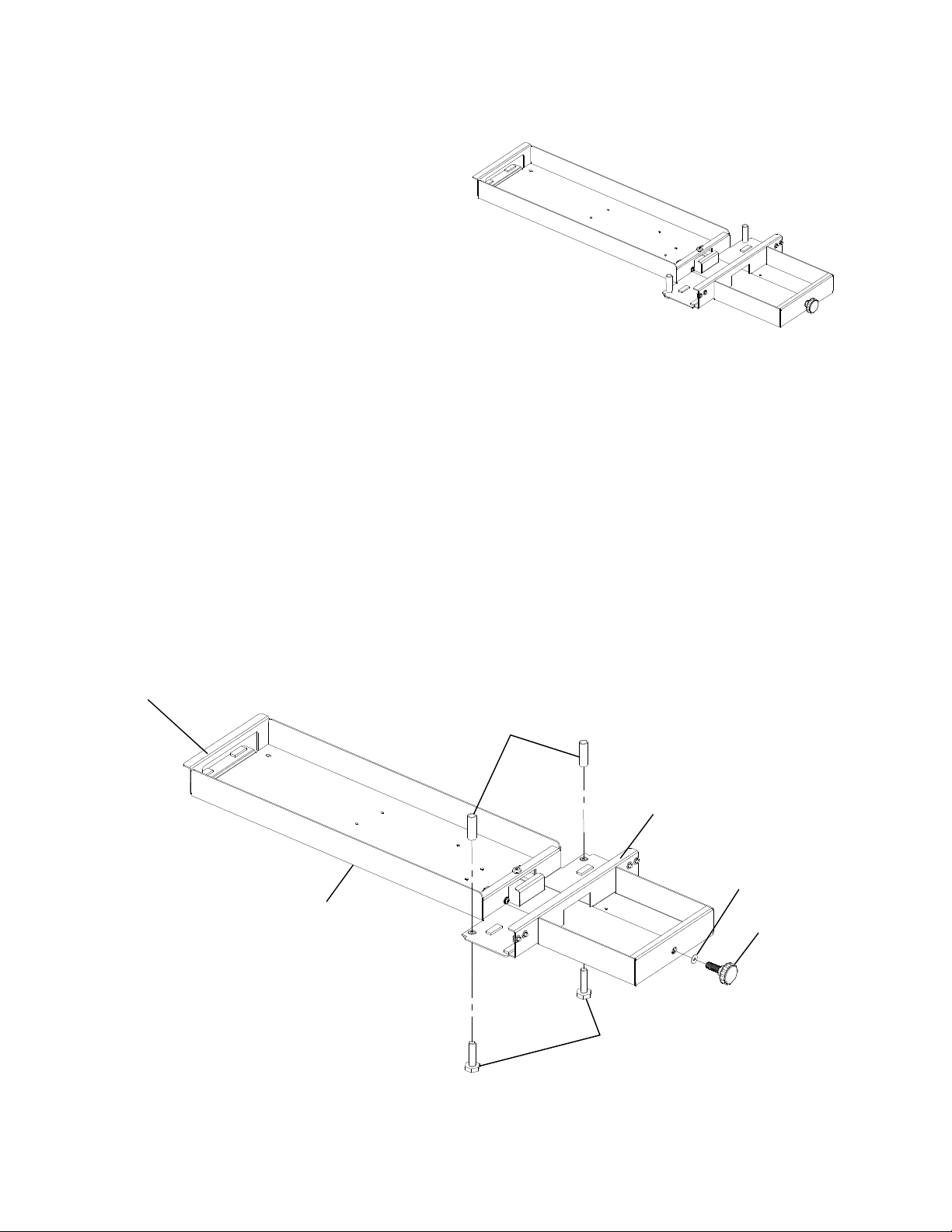
5. While holding the unit in place, align the two Plastic
Rollers (removed in step 1) with the holes in the top
of the bracket. See figure 4. The Rollers should be
between the worksurface and the bracket.
6. Re-install the two Locking Bolts (removed in step 1)
into the holes as shown in figure 4. Thread them all
the way in and tighten using the 9/16” wrench.
7. Re-install the Locking Knob and 3/8” nylon washer
(removed in step 1). Do not tighten.
Figure 4
(Worksurface not shown)
Nylon washer
Locking Knob
Plastic Rollers
3/8” x 1-1/2” hex
head bolts
Sliding Keyboard/Pedestal Bracket
assembly
Hole
Eaton
1000 Eaton Boulevard
Cleveland, OH 44122
United States
Eaton.com
© 2018 Eaton
All Rights Reserved
Printed in USA
Publication No. IL211024EN 91647
May 2018
Eaton
160 Gold Star Boulevard
Worcester, MA 01606
United States
800-225-7348
508-852-4300
Eaton.com/furniture
Follow us on social media to get the
latest product and support information.
Eaton is a registered trademark.
*All trademarks are property
of their respective owners.
Figure 4.
(Worksurface not shown)
5. While holding the unit in place, align the two
Plastic Rollers (removed in step 1) with the holes
in the top of the bracket. See gure 4. The Rollers
should be between the worksurface and the
bracket.
6. Re-install the two Locking Bolts (removed in step
1) into the holes as shown in gure 4. Thread them
all the way in and tighten using the 9⁄16" wrench.
7. Re-install the Locking Knob and 3⁄8" nylon
washer(removed in step 1). Do not tighten.