Eaton EPM12V2 User manual

EPM12V2 Evaluation kit user guide

32
EPM12V2 Evaluation kit user guide EPM12V2 Evaluation kit user guide
EPM12V2 EVALUATION KIT USER GUIDE Technical note ELX1037 April 2021 www.eaton.com/magnetics EPM12V2 EVALUATION KIT USER GUIDE Technical note ELX1037 April 2021 www.eaton.com/magnetics
Contents
INTRODUCTION .........................................................3
IMPORTANT NOTICE ......................................................3
DESCRIPTION ............................................................3
SPECIFICATION ..........................................................4
TEST SET-UP ..........................................................4-5
OPERATION NOTES.....................................................5-9
TEST RESULTS .........................................................10
SCHEMATIC ............................................................11
LAYOUT ................................................................11
COMPONENT LIST ......................................................11
Introduction
This document describes the operations of evaluation kits (EVK) concerning the Eaton’s EPM DC-DC non-isolated converter
product. The EVK includes test points for all main points where probing is necessary for evaluation. The EVK supports many options
for Eaton’s product configuration. Using these options, the user is allowed to test all desired electrical specifications. This guide
describes the test configurations and typical equipment setup. The typical input and output waveforms are also presented.
Important notice
• Please read the product datasheet and EVK user guide before using the EVK.
• Please do not remove the product from the EVK.
• This product is an ESD sensitive component and should be tested in an ESD protected area.
• The EVK is designed to operate in clean and dust-free office or laboratory. The EVK should be protected from sunlight and
sources of heat, and making sure air is flowing across the tool. Please keep it away from vibration or strong electromagnetic
fields generated by electrical equipment.
• When connecting and disconnecting the power interface, please turn off the power supply to avoid accidental short circuits
causing injury.
• The power connection must avoid reverse voltage application.
• During the test, the electrical rating should be kept within the range specified in the data sheet.
Description
This EVK supports user test electrical performance of Eaton’s DC-DC non-isolated converter part number EPM12V2-05R5-12R0P
and EPM12V2-05R5-12R0N.
Figure 1 shows the EPM12V2 EVK (PN: EPM12V2-P-EVK, positive logic), (PN:EPM12V2-N-EVK, negative logic) and function outline.
This EVK is made up of the input and output connectors and the DC/DC converter. There are six additional functions, output voltage
trim function, voltage sense, remote on/off function, power good, synchronization, and sequencing.
Figure 1. EPM12V2 EVK

54
EPM12V2 Evaluation kit user guide EPM12V2 Evaluation kit user guide
EPM12V2 EVALUATION KIT USER GUIDE Technical note ELX1037 April 2021 www.eaton.com/magnetics EPM12V2 EVALUATION KIT USER GUIDE Technical note ELX1037 April 2021 www.eaton.com/magnetics
Figure 2: Test set-up example
Specifications
Table 1 shows the EPM12V2 EVK general performance specifications. The EPM12V2 EVK can deliver up to 12 A of output current
and with a wide DC input. The modules can achieve high efficiency up to 91%, wide operation temperature from -40 °C to +90 °C,
and has short circuit protection. Input range is from 3 V to 14.4 V, nominal input voltage is 12 V. Please refer to the product data
sheet for the detailed specifications EPM12V2 data sheet.
* The output voltage range is limited by Vin. (Vout ≤ Vin -2 Vdc)
** Ripple & noise: Measured with 20 MHz bandwidth and 47 µF + 47 µF + 0.1 µF ceramic capacitor.
Table 1- General specifications
Parameter Conditions Minimum Nominal Maximum Unit
Input
Input
voltage 3 12 14.4 Vdc
Input
current
Vin=nom,
no load
30 mA
Start-up
voltage
Iout=0% ~
100% load
3 Vdc
Output
Voltage
trim*
0.6 5.5 Vdc
Minimum
load
0 %
Output
current
Full load 12 A
Ripple
and noise**
Vo < 1.2 V
Vo ≥ 1.2 V 3% Vo
50 mVp-p
mVp-p
Test set-up
Operation notes
Output voltage trim function
Using a resistor in parallel between Trim and SIG_GND (Figure 3) can adjust the output voltage of the converter. The
following formula can calculate the trim resistor of the corresponding voltage.
12
Rtrim (kΩ) =Vo−0.6
Figure 3: Voltage trim resistor diagram Figure 4: 5 V trimming output example
Refer to Table 3 for the basic values of the resistors and switch positions. Only one switch should be on at a time. Figure 4
is an example for trimming 5 V output voltage.
Table 2- Pin configuration
Connector Function Pin
symbol Description
J1 Input terminal VIN
GND Connect the VIN and GND terminals to the DC power source respectively.
J2 Output terminal VO
GND
Connect the VO and GND terminals to the (electronic) load.
JP1/JP6 Input voltage
measuring point
+VIN
GND
Connect the +VIN and GND terminals to the voltage meter.
JP2 Functional
terminal
SYNC Synchronization can be done by using the external signal applied to the SYNC of the module. If synchronization is not
being used, connect the SYNC to GND.
SEQ The SEQ can be used when master-slave power-supply tracking is required.
PG The Power Good signal
indicates that the output voltage regulation is in the specification limits.
5 V For use with remote
function, connect to a 5 V power supply
CTRL Switch the module on or off through controlling CTRL (or Remote on/off) signal in positive logic or negative logic.
GND Ground.
JP3 Voltage sensing VS+
VS-
VS+ and VS- are remote sense pins. VS+ and VS- are connected to the positive and negative terminal of the load or output
terminal
respectively for voltage sensing.
JP4 Output ripple
measuring point
+VO
GND
Connect the +VO and GND terminals to the probe with short ground lead.
JP5 Output voltage
measuring point
+VO
GND
Connect the +VO and GND terminals to the voltage meter.
SW1 Volatge trim
selector
1, 2, 3,
4, 5, 6
Adjust the output voltage with trim resistors. There is a DIP switch with six choices for six voltages.

76
EPM12V2 Evaluation kit user guide EPM12V2 Evaluation kit user guide
EPM12V2 EVALUATION KIT USER GUIDE Technical note ELX1037 April 2021 www.eaton.com/magnetics EPM12V2 EVALUATION KIT USER GUIDE Technical note ELX1037 April 2021 www.eaton.com/magnetics
Remote on/off function
The EVK can switch the converter on or off by controlling the Remote ON/OFF signal in positive logic. If the status of ON/
OFF is open or from 1.6 V to 5 V, the converter will turn on. Otherwise, if the status of ON/OFF is short to ground or from 0 V
to 0.6 V, the converter will shut down.
The remote control circuit on EVK shows below. There are CTRL and 5 V pins at connector JP3. For example, when CTRL is
high level, the converter will shut down. When CTRL is low level, the converter will turn on.
Figure 7: Remote on/off circuit diagram
Table 4- Remote on/off conditions
Condition CTRL Q1
DC-DC ON Low level Off
DC-DC OFF High level On
Figure 8: CNTL low level, DC-DC on Figure 9: CNTRL high level, DC-DC off
Table 3- Resistor value and switch position
Output voltage Calculated
Rtrim Option
5 V 2.7 kΩ SW 1 : on
3.3 V 4.7 kΩ SW 2 : on
2.5 V 6.2 kΩ SW 3 : on
1.8 V 10 kΩ SW 4: on
1.5 V 13 kΩ SW 5 : on
1.2 V 20 kΩ SW 6 : on
Voltage sensing
VS+ and VS- is the voltage sensing pin at the JP3 connector. VS+ and VS- are connected to the positive and negative
terminal of the load respectively. This function makes the converter detect the voltage across the load without being
disturbed by the impedance of the wires. The sense wire is not the main path of the system and carries a low current. It is
recommended to use twisted wires for the VS+ and VS- wires or shielded cables to avoid noise and unwanted inductance. If
voltage sensing is not needed, VS+ and VS- should connect to the positive and negative output terminals of the converter by
using the zero-ohm resistor each.
Figure 5: Voltage sense configuration Figure 6: No voltage sense configuration
Positive logic
Table 5- Remote on/off conditions
Condition CTRL Q1
DC-DC ON High level On
DC-DC OFF Low level Off
Negative logic
Figure 10: CNTL high level, DC-DC on Figure 11: CNTRL low level, DC-DC off

98
EPM12V2 Evaluation kit user guide EPM12V2 Evaluation kit user guide
EPM12V2 EVALUATION KIT USER GUIDE Technical note ELX1037 April 2021 www.eaton.com/magnetics EPM12V2 EVALUATION KIT USER GUIDE Technical note ELX1037 April 2021 www.eaton.com/magnetics
Synchronization
The frequency of EVK can be synchronized with an external signal. The external signal should be in the specified range and
applied to the SYNC pin as shown in Figure 12. The converter will synchronize by the rising edge of the external signal. If the
synchronization function is not needed, connect the SYNC pin to the ground.
Figure 12: External signal to SYNC circuit diagram
Table 6- Synchronization general specifications
Parameter Minimum Typical Maximum Unit
Synchronization frequency range 800 840 kHz
High level input voltage 2 V
Low level input voltage 0.8 V
Input current SYNC 1 µA
Figure 14:
Figure 13:
Power good
The PGOOD signal can indicate the output voltage regulation is within the specification limits. This open-drain output goes
low during over current, short-circuit, UVLO, overvoltage and under voltage, over temperature, or when the output is not
regulated (such as a pre-bias output). The PGOOD should connect through a pull-up resistor to a source of 5 Vdc. The Power
good design on EVK is shown in Figure 15.
Figure 15: PGOOD circuit diagram
Figure 16: PGOOD curve
Output voltage sequencing
The sequencing feature can fulfill the end user to sequencing the output voltage and is achieved by dividing down the
master’s output voltage with a resistor network as shown in Figure 17. Rseq equals R5 on the evaluation board, and Rtrim
equals R6.
When an analog voltage is applied to the SEQ pin, the output voltage tracks this voltage until the output reaches the
set-point voltage. By connecting multiple modules, multiple modules can track their output voltages to the voltage applied on
the SEQ pin. Besides, a small capacitor (suggested value is 100 pF) can be connected across the Rtrim. If there is no need
for the sequencing feature, leave the SEQ pin open.
Figure 17: Sequencing circuit diagram
Figure 18: Sequencing curve

10
EPM12V2 Evaluation kit user guide
EPM12V2 EVALUATION KIT USER GUIDE Technical note ELX1037 April 2021 www.eaton.com/magnetics
Test results
EVK set-up and operation wave form
Model number: EPM12V2 EVK
Conditions: Ta=+25 °C, VIN=12 V, VO=5 V, IO=12 A (full load). This ΔT plus ambient should remain below the specified maximum operating
temperature for the module (please refer to the EPM12V2 data sheet).
Start-up
Shut-down
Ch1: Input voltage (5 V/div.)
Ch2: Output voltage (2 V/div.)
Time scale: (1 ms/div.) Ch1: Input voltage (5 V/div.)
Ch2: Output voltage (2 V/div.)
Time scale: (1 ms/div.)
Output ripple and noise Transient response (75%-100% load)
Ch1: Output voltage (50 mV/div.) Time scale: (1 us/div.) Ch1: Input voltage (5 V/div.)
Ch2: Output voltage (50 mV/div.)
Time scale: (100 us/div.)
Ch4: Output current (10 A/div.
)

Eaton
Electronics Division
1000 Eaton Boulevard
Cleveland, OH 44122
United States
Eaton.com/electronics
© 2021 Eaton
All Rights Reserved
Printed in USA
Publication no. EXL1037 BU-ELX21037
April 2021
Eaton is a registered trademark.
All trademarks are property
of their respective owners.
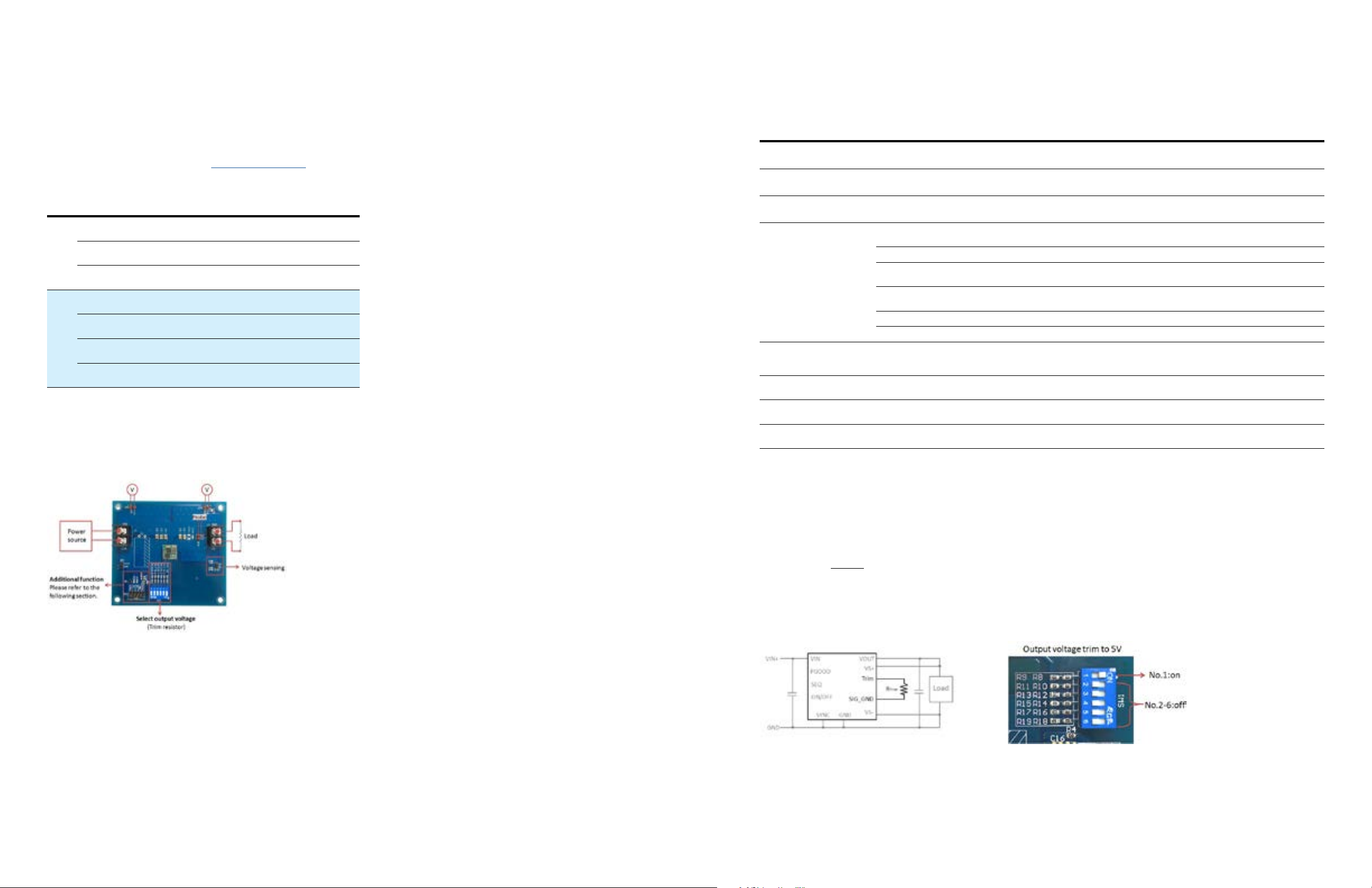
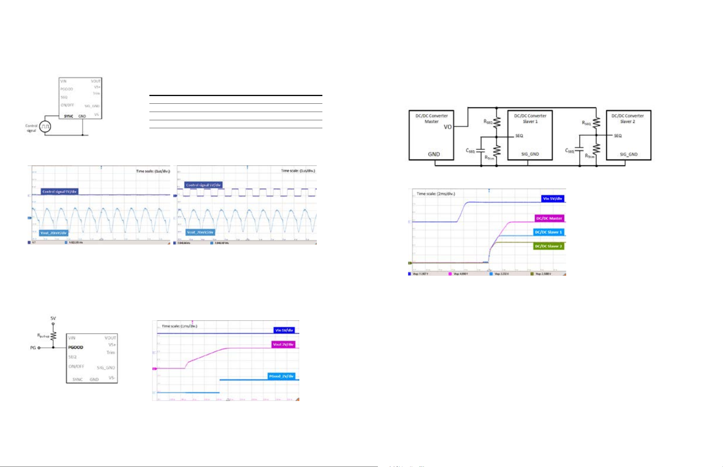
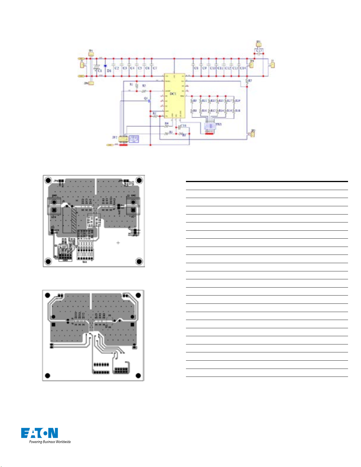
Schematic
Component list
Layout
Description Qty Designator
EPM12V2 EVK 1
Capacitor, X7R, 1210, 10UF±10%, 50V 5C2, C3, C4, C5, C6
Capacitor, X7R, 1210, 47UF±10%, 10V 2C8, C9
Capacitor, X7R, 0805, 0.1UF±10%, 50V 2C14, C15
MOSFET, AO3442 (SOT-23), 100V, N-Channel 1 Q1
Resistor, 0805, 10KΩ, 1% 2R1, R2
Resistor, 0805, 0Ω, 5% 3R3, R4, R7
Resistor, 0805, 2.55KΩ, 1% 1 R8
Resistor, 0805, 200Ω, 1% 1 R9
Resistor, 0805, 2.2KΩ, 1% 2R10, R11
Resistor, 0805, 3KΩ, 1% 1 R12
Resistor, 0805, 3.3KΩ, 1% 1 R13
Resistor, 0805, 10KΩ, 1% 1 R14
Resistor, 0805, 0Ω, 5% 1 R15
Resistor, 0805, 13KΩ, 1% 1 R16
Resistor, 0805, 330Ω, 1% 1 R17
Resistor, 0805, 470Ω, 1% 1 R13
Resistor, 0805, 20KΩ, 1% 1 R18
Resistor, 0805, 0Ω, 5% 1 R19
Capacitor, 220UF/200V, KXJ series, 12.5x25 mm 1 C1
Terminal Block, 2P, 250V, 15A 2J1, J2
DIP Switch, six choices 1 SW1
Pin Header, single row, 14.2mm, 2P 5JP1, JP3, JP4, JP5, JP6
Pin Header, dual row, 14.2mm, 10P 1 JP2
Table of contents
Other Eaton Motherboard manuals