EBS Ink-Jet Systems 1500 Series User manual

EBS
Ink Jet Systems
EBS 1500 series
USER'S MANUAL
In
k
-Jet technology for the future


EBS-1500 Series Printers User's Manual EBS
Ink Jet Systems
2 20060920#3.1
©2006 EBS Ink-Jet Systems GmbH, D-51588 Nümbrecht

EBS
Ink Jet Systems EBS-1500 Series Printers User's Manual
20060920#3.1 3
TABLE OF CONTENTS
1. GENERAL INFORMATION ..................................................................................7
1.1. ENVIRONMENTAL PROTECTION ............................................................................................7
1.2. APPLICATION .....................................................................................................................7
Short Description of the Printer:.............................................................................7
EBS-1500
Print Heads.................................................................................8
EBS-1500
General-purpose Controller........................................................9
1.3. PRINCIPLE OF OPERATION ................................................................................................10
Electromagnetic Print Heads................................................................................10
2. INSTALLING THE PRINTER..............................................................................11
2.1. SAFETY REQUIREMENTS ...................................................................................................11
2.2. POWER AND AIR SUPPLY REQUIREMENTS .........................................................................12
Power Supply.............................................................................................................................12
Air Supply...................................................................................................................................12
2.3. INSTALLING THE UNIT........................................................................................................12
2.3.1. Printer accessories ......................................................................................................12
2.3.2. Preparatory Steps ........................................................................................................13
2.3.3. Removing Transport Protections ...............................................................................14
2.3.4. Connections..................................................................................................................14
Earthed neutral system.........................................................................................15
Connecting the head ............................................................................................15
Connecting the photo detector.............................................................................15
Connecting the shaft-encoder ..............................................................................16
Connecting external data transfer devices...........................................................16
Connecting the Ink Monitor System - IMS............................................................16
Connecting the head to the ink and compressed air systems..............................16
Connecting the head to the pump-based ink system...........................................18
2.3.5. Installing a new Bottle of Ink (or Replacing an Empty One)....................................18
Connecting a new ink bottle (or replacing an ink bottle) in the compressor-
based system .......................................................................................................18
Connecting a new ink bottle (or replacing an ink bottle) in the ink system
with an ink pump...................................................................................................19
2.4. REMOVING THE HEAD COVER............................................................................................19
3. STARTING THE PRINTER.................................................................................20
3.1. SWITCHING THE PRINTER ON............................................................................................20
3.2. SWITCHING THE PRINTER OFF...........................................................................................20
4. OPERATING THE PRINTER..............................................................................21
4.1. OPERATION PANEL...........................................................................................................21
4.2. OPERATING THE PRINTER WITH CONTROL MENU..............................................................23
4.3. PRINT HEAD STATUS ........................................................................................................26
4.4. CONTROLLING THE PRINTER .............................................................................................27
4.4.1. Text Files.......................................................................................................................27
4.4.1.1. Introduction to Text Files .........................................................................................27
WORD PROCESSOR – A Description of Control Keys.......................................28
4.4.1.2. Opening and Editing a New File ..............................................................................29
Subfile type: TEKST – ASCII characters................................................................29
Subfile type: GRAPHICS..........................................................................................31
GRAPHIC PROCESSOR – A description of function keys..................................32

EBS-1500 Series Printers User's Manual EBS
Ink Jet Systems
4 20060920#3.1
Subfile type: BAR CODE .........................................................................................33
Subfile type: Text file Name .................................................................................34
4.4.1.3. Editing an Existing Subfile .......................................................................................35
4.4.1.4. Copying and Editing a Text file ................................................................................35
4.4.1.5. Deleting a Text file ...................................................................................................35
4.4.1.6. Deleting the File Library...........................................................................................36
4.4.1.7. Accessing the File Library........................................................................................36
4.4.1.8. Linking File Names with Parameter-block Names...................................................37
4.4.1.9. Using the Password.................................................................................................37
Defining a User Password....................................................................................37
Switching the Password Function On...................................................................38
Changing the User Password...............................................................................38
Deleting the user password..................................................................................38
4.4.1.10. Using Special Registers...........................................................................................39
Object Counters....................................................................................................39
Date and Time......................................................................................................40
Universal Counter.................................................................................................41
Universal Date and Time......................................................................................46
Expiry Date Registers...........................................................................................47
Data from Special Channel...................................................................................48
4.4.2. Using Print-parameter Blocks.....................................................................................48
4.4.2.1. Creating and Editing a New Parameter Block .........................................................49
Modifying Parameters...........................................................................................49
4.4.2.2. Editing Existing Blocks of Parameters.....................................................................50
4.4.2.3. Copying and Editing Blocks of Parameter ...............................................................50
4.4.2.4. Deleting a Block of Parameters ...............................................................................50
4.4.2.5. Deleting the Parameter-block Library ......................................................................50
4.4.2.6. Accessing the Parameter Block Library...................................................................51
4.4.3. Printing..........................................................................................................................52
4.4.3.1. Stopping the Printing ...............................................................................................52
4.4.3.2. Starting the Printing .................................................................................................52
4.4.3.3. Quick Stopping the Printing .....................................................................................53
4.4.3.4. Print Parameters......................................................................................................53
Modifying Print Parameters..................................................................................54
Vertical Direction ..................................................................................................55
Initial Distance......................................................................................................55
Number of Repetitions..........................................................................................55
Distance Between Overprints...............................................................................56
Horizontal Direction..............................................................................................56
Overprint Height ...................................................................................................57
Date Offset ...........................................................................................................58
Counter Increment................................................................................................58
Row Repetition.....................................................................................................58
Ink drop Intensity..................................................................................................59
Timing Mode.........................................................................................................59
Character Resolution............................................................................................59
Conveyor travel speed..........................................................................................60
Number of Pulses Generated by External Encoder.............................................60
Number of purging rows during the automatic nozzle-purge procedure..............60
Purge period during the automatic nozzle-purge procedure................................61
4.4.3.5. Saving Current Parameters in a Block ....................................................................61
4.4.3.6. Controlling Object Counters.....................................................................................62
Accessing object counters....................................................................................62
Modifying Object Counters...................................................................................62
4.4.3.7. Printing with the use of a code switch .....................................................................63
4.4.3.8. Viewing Files on the Terminal Display.....................................................................63
4.4.4. Servicing the Head.......................................................................................................64
4.4.4.1. Defining Some Print Parameters with the Conveyor Travel Speed.........................64
4.4.4.2. Other Commands ....................................................................................................64
4.4.5. Auxiliary Commands....................................................................................................65

EBS
Ink Jet Systems EBS-1500 Series Printers User's Manual
20060920#3.1 5
4.4.5.1. System information ..................................................................................................65
4.4.5.2. Accessing Alarm Messages.....................................................................................65
4.4.5.3. Setting Date and Time .............................................................................................65
4.4.5.4. Checking the Printer Run Hours ..............................................................................66
4.4.5.5. Choosing a Language..............................................................................................66
4.4.5.6. Releasing Protections..............................................................................................66
4.4.6. Replacing ink bottle .....................................................................................................68
General information..............................................................................................68
Replacing the bottle of ink....................................................................................69
4.4.6.1. Checking the validity date........................................................................................70
4.4.6.2. Checking the calculated ink consumption level .......................................................71
4.4.6.3. Accessing information in the Ink Monitoring System...............................................71
4.4.6.4. Problems that might arise in the printer operation when a bottle of ink is
replaced ...................................................................................................................72
Flow diagram for the ink monitoring system.........................................................72
4.5. ALARMS,ERRORS AND INDICATIONS .................................................................................73
4.5.1. Clearing Alarms............................................................................................................75
4.6. ADJUSTING THE PRINT RATE.............................................................................................75
4.6.1. Internal Generator ........................................................................................................75
4.6.2. Shaft-encoder ...............................................................................................................76
4.6.3. Defining the Maximum Print Rate for Various Fonts................................................78
5. EXAMPLES OF HOW TO OPERATE THE PRINTER .......................................79
5.1. HOW TO PRINT THE FIRST SAMPLE TEXT FILE? .................................................................79
5.2. CREATING AND PRINTING SAMPLE TEXT FILES ..................................................................81
5.2.1. How to Print the Current Date and Time?..................................................................81
5.2.2. How to Print Consecutive Numbers?.........................................................................82
5.2.3. How to Print Expiry Date? ...........................................................................................83
5.2.4. How to Print Logos? ....................................................................................................84
5.2.5. How to Print a Bar Code?............................................................................................85
5.2.6. How to Print a Complex Subfile?................................................................................85
6. SERVICING AND MAINTENANCE OF THE PRINTER .....................................88
6.1. ROUTINE MAINTENANCE ...................................................................................................88
6.2. REMOVING AIR FROM THE INK SYSTEM..............................................................................89
6.3. REPLACING THE INK FILTER ..............................................................................................89
6.4. WHEN PROBLEMS ARISE WHILE OPERATING OR SERVICING THE PRINTER ..........................89
The printer does not switch on................................................................................................89
No overprints are made after the print command has been accepted ................................90
Clogged nozzles in the head....................................................................................................90
Some dots are much smaller than others or are missing.....................................................91
Adjusting valve electromagnets in electromagnetic heads ..................................91
Overprints are distorted ...........................................................................................................93
Overprints made with the electromagnetic head look like printed in bold and
blurred ...........................................................................................................................95
Overprints are slanted ..............................................................................................................95
Lower (upper) parts of overprints are distorted.....................................................................96
Some vertical rows are missing in overprints........................................................................96
Overprints are not straight, they are wavy or jagged............................................................97
Mixed text names in the library – the battery is discharged.................................................97
6.5. HOW TO CONTACT YOUR SERVICE REPRESENTATIVE? ........................................................98
7. STORAGE AND TRANSPORTATION...............................................................99
7.1. STORING THE PRINTER .....................................................................................................99
7.2. TRANSPORTING THE PRINTER .........................................................................................100

EBS-1500 Series Printers User's Manual EBS
Ink Jet Systems
6 20060920#3.1
8. MULTI-HEAD INK-JET PRINTERS..................................................................101
9. TECHNICAL SPECIFICATIONS ......................................................................102
APPENDIX A - LAYOUT OF CYRILLIC CHARACTERS ON THE PRINTER
TERMINAL KEYPAD ...................................................................105
APPENDIX B - LAYOUT OF ARABIC CHARACTERS ON THE PRINTER
TERMINAL KEYPAD ...................................................................106
Index......................................................................................................................107
Dear User,
This Manual contains very useful information on how to operate your Ink-
Jet Printer. Please read this Manual carefully.
This version (3.1) of the document applies to EBS-1500 printers with a single electromagnetic
head and is the continuation of the operating instructions (version 20.8), which applied to
EBS-1500 printers with all head types, including multi-head systems. The document incorporates
most changes introduced to EBS printers in software versions from 16_1A to 21_0A and the
descriptions contained therein apply to the equipment where such software versions are installed.
As the machine and options can be customised, the product delivered to you depends on your
specific order. Therefore some descriptions or illustrations may differ slightly from your
equipment. As we need to keep pace with new technological advancement, we reserve the right
to introduce changes in the design and technical solutions adopted. In view of the above, no
data, illustrations or description shall make grounds for any claims. Should your printer be
equipped with options that are not described or illustrated in the Manual or should you have
additional queries after having read the Manual, please contact any EBS representative for more
information.

EBS
Ink Jet Systems
EBS-1500 Series Printers User's Manual
Paragraph 1 - General Information
20060920#3.1 7
1. General Information
NOTE:
There are warning and information signs on the right or left hand-side margins of some pages to
attract user’s attention to messages that are provided next to them. They are the following signs:
!
Information signs indicating:
•that the actions described should be taken carefully,
•additional, printer-specific option and features,
•untypical behaviour of the unit,
•other hints.
!
A warning not to take the action that might have a critical impact on the
proper operation of the unit. It requires the user to follow closely
instructions given therein.
The Manufacturer reserves the right to introduce changes whose description
may not be provided in this manual.
The Manufacturer shall not bear any responsibility for damages resulting from
the failure to follow the instructions or consequences of editorial or
publishing errors within the instructions.
1.1. Environmental protection
On withdrawing EBS-1500 printers and printing systems from use do not take
system elements out together with other waste. Pursuant to Directive No. 2002/96/EC of
the Council of the European Community on waste electrical or electronic equipment, the
elements of the EBS-1500 printers and printing systems must be separated from
other waste after they have been withdrawn from use and processed in an environmentally
friendly way.
1.2. Application
EBS-1500 is a family of industrial INK JET printers designed for labelling in a non-
contact way, various objects that move on a line conveyor, for example. The printer provides
clear and firm overprints on such materials as:
•paper and cardboard,
•(porous) plastics,
•fabric,
•leather and leatherette,
•wood and wood-like products,
•(porous) ceramic products,
•metal surfaces of any type, etc.
Short Description of the Printer:
Every EBS-1500 series printer consists of a general-purpose controller and
a print head.
!

EBS-1500 Series Printers User's Manual
Paragraph 1 - General Information EBS
Ink Jet Systems
8 20060920#3.1
EBS-1500
Print Heads
The print heads have the following traits:
´They are independent on the controller and therefore the heads can be installed closely
next to the object being labelled, which is not in an easily accessible place very often.
´They are connected with the controller via a 3 m long flexible cord as a standard (up to
30 m optionally).
1500/00 series electromagnetic heads, where the nozzle valve is controlled with an
electromagnet. One head can contain 5, 7, 12, 16, 25, 32 or 64 nozzles. A printer equipped
with such heads can produce 6 to 115 mm high overprints with one head.
´The electromagnetic head can be set at any position.
´Inks of various types and colours can be used according to the surface to be printed on.
Electromagnetic 7to 16-nozzle head
Electromagnetic 25 to 32-nozzle head
Electromagnetic 64-nozzle head

EBS
Ink Jet Systems
EBS-1500 Series Printers User's Manual
Paragraph 1 - General Information
20060920#3.1 9
EBS-1500
General-purpose Controller
The controller has the following traits:
´Separate controller types for electromagnetic or piezoceramic print head families.
´Splash-proof stainless steel INOX housing and a membrane keypad to ensure that the
controller is resistant to water and all types of solvent that might be used in the real
working environment.
´All connectors grouped on the same side wall to facilitate the installation of the printer in
a place where the space is very limited.
´Printing capabilities:
•texts composed of small and capital letters of various types, also printed in boldface
or rotated,
•several lines of text printed during a single run of an object in front of the print head
(a maximum of 6 lines with no space between the lines),
4
lines
(7x5)
5
lines
(5x5)
6
lines
(5x5)
•diacritical national characters,
•graphics – a built-in set of ready-to-use graphic signs and a tool-kit for creating
user-defined graphics,
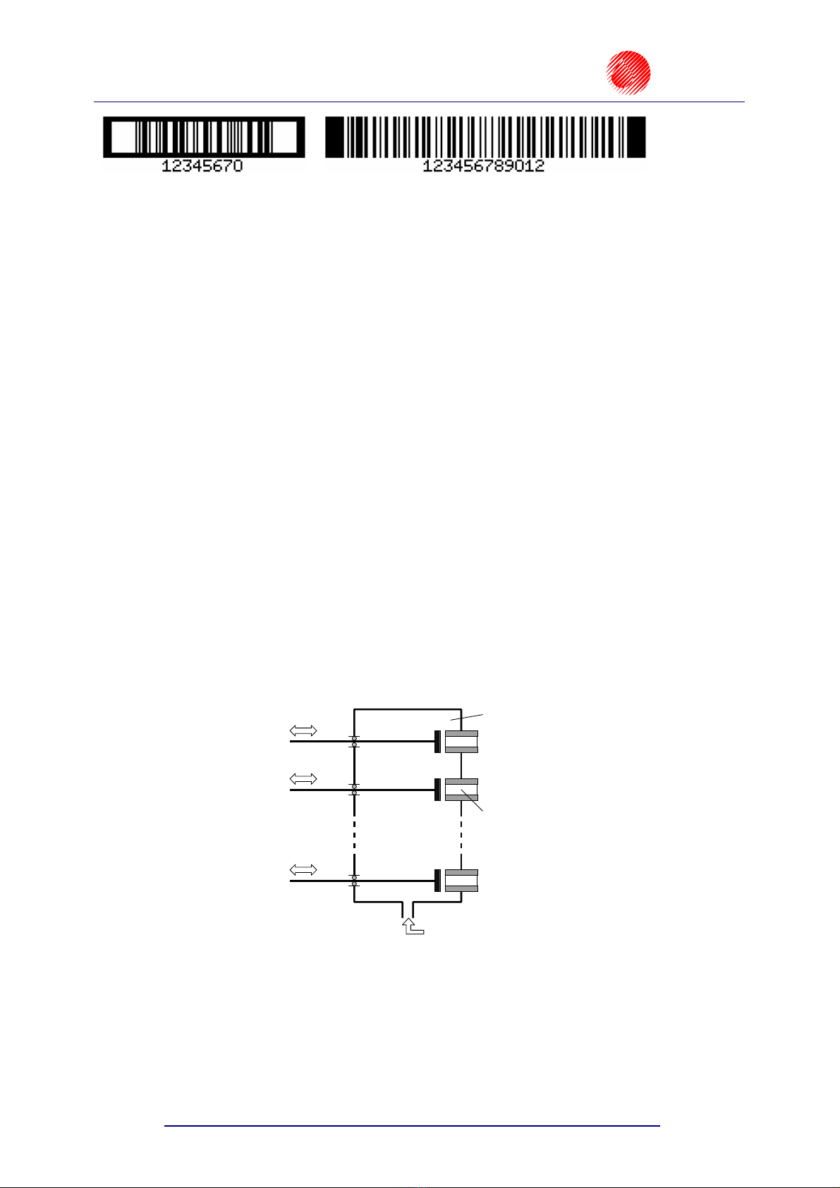
•bar codes of various kinds, printed in a regular way or in reverse, with or without
a caption of digits; an option of introducing on-going changes to the digital contents of
the code (bar code as an incremental or decremental counter)
EBS-1500 Series Printers User's Manual
Paragraph 1 - General Information EBS
Ink Jet Systems
10 20060920#3.1
•variable data - such as current date, warranty expiration date, current time, ascending
and descending numbering (counters), any types of data, which are transferred from
a PC or external devices (via an optional special channel), as required and arranged
by the user.
´Labels can be input or modified easily with the use of a built-in terminal or a PC (via
RS-232 or RS-485 interface).
´An optional PC can be connected in order to:
•control the operation of one printer via the program EdGraf,.
•allow a number of EBS printers of various types, linked together into a network, to be
controlled from one computer via the program InkNet.
´Objects to be labelled are detected by a photo-detector.
´Fully automatic printer’s operation with the status indication and instructions for
performing service operations.
´Bottles of ink are fully controlled and bottles designed for different, incompatible types of
EBS printers are not accepted.
´Continuous operation over 24 hours a day.
1.3. Principle of Operation
Electromagnetic Print Heads
Every label consists of a number of a droplet-wide vertical rows. Nozzles are set in the
print head vertically, at regular intervals from each-other. This determines the maximal height
of the label. Every nozzle is equipped with an electromagnet-controlled valve. Labels are
made by ink droplets that are jetted at a pressure when the valves open. The pressure is
generated by an external system and controlled with a pressure regulator. Objects to be
labelled move in front of the print head and vertical rows are printed one by one to complete
the entire label.
A
n electromagnet to
control the valve
Supply of ink to the
chamber at high pressure
Surge chamber
Nozzle
Valve 1
Valve 2
Valve n

EBS
Ink Jet Systems
EBS-1500 Series Printers User's Manual
Paragraph 2 - Installing the Printe
r
20060920#3.1 11
2. Installing the Printer
2.1. Safety Requirements
All efforts have been put into designing this device carefully and making it safe and reliable.
However, the safe operation of the device is conditioned by the user’s awareness of, and
obedience to the following safety rules and precautions.
The unit should be operated by the staff that has been trained. It is recommended that
the operation of the printer is supervised.
1. A fire extinguisher designed to extinguish electrical equipment and flammable
solvent fire must be placed within easy reach near the unit.
2. The unit must not be operated in rooms where an explosion hazard exists.
3. The unit must not make overprints on objects whose temperature exceeds 100 °C.
4. No open fire or spark producing devices are allowed in the area where the printer
operates.
5. Power supply cord must be connected to a socket where a protective pin is used.
The efficiency of the earth should comply with the applicable standards.
6. As high voltage occurs in the printer, make sure that all manipulations in the
electrical part of the system and inside the head are performed after power has
been switched off.
7. The outlet of the head must not be directed towards persons, animals or accidental
objects during printing in order to avoid splashing anybody or anything with ink.
8. Protective clothes and possibly protective glasses need to be warn by persons
performing any work on the ink system.
9. No plastic vessels should be used to do the washing as they collect static electricity.
Metal vessels are recommended.
10. No ink, solvent or wash-up (or waste fluid remaining after the head has been washed)
should be left in open vessels as these inflammable fluids may ignite from accidental
sources of fire.
WARNING:
Static electricity collected by people (on their plastic clothes or in their hair, for example) may
spark-over to ink or wash-up vessels when they have been left open. The ink and wash-up
are inflammable and may get ignited! Therefore, before you approach the open vessels
with inflammable fluids, discharge the static electricity by touching the metal printer housing or
another metal object that is connected to the earth.
In the case of accident...
´When ink or solvent spills occur, the spilled fluid should be wiped with a piece of
absorbent material and then removed in compliance with fire and health and safety at
work (HSE) regulations.
´If the clothing has been splashed, remove it as soon as possible.
´Should the eyes or skin get irritated:
EYES need to be rinsed with running water for at least 15 minutes, then you
should see your oculist,
SKIN needs to be washed with water and soap.
!
!
!
EBS-1500 Series Printers User's Manual
Paragraph 2 - Installing the Printer EBS
Ink Jet Systems
12 20060920#3.1
2.2. Power and Air Supply Requirements
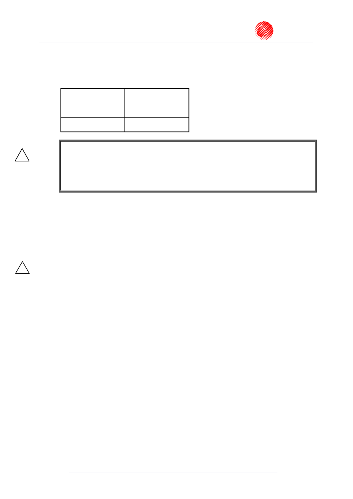
Power Supply
Standard
Supply voltage 100 - 240V (AC)
90 - 350V (DC)
Mains frequency 45 - 440Hz
NOTE:
•The mains electricity must meet the requirements of the applicable standards. Otherwise
measures need to be taken or devices used to ensure that the proper power is applied to
the printer.
•The mains socket should be equipped with a protective pin properly connected to
earth. The efficiency of the earth needs to comply with the applicable standards.
Air Supply
Ink pressure can be generated by an external compressor system or inside the ink
system if the system is equipped with an ink pump. The application of the ink system with
a pump simplifies the structure of the printing system significantly. A detailed description of
the device is contained in the document entitled Ink System with an Ink Pump.
Regulator inlet air pressure: 0,5 - 10 bar (0,05 - 1,0 MPa).
NOTE: If a compressor system is used, supply air must be free from any impurities.
Otherwise ink gets dirty sooner inside the ink system and overprints of lower
quality may result.
If air supplied from the compressor system is likely to contain any of the
above-mentioned substances, filtering elements absolutely need to be
installed immediately before the ink system connection to remove such
impurities as water, oil or others.
The Manufacturer shall not bear any responsibility for
improper operation of the unit, if the malfunction is caused
by air contamination.
2.3. Installing the unit
2.3.1. Printer accessories
In view of a great number of EBS printers and printing systems, the set of accessories
depends on a specific user application. This section gives a specification of the accessories
that are used most frequently in various printer configurations.
Typical printer accessories include:
a). Elements and units which are needed for the printing process in every configuration,
b). Additional and supportive elements and units which are needed for a given configuration
to satisfy user requirements.
List of elements and subassemblies:
Head controller.
!
!

EBS
Ink Jet Systems
EBS-1500 Series Printers User's Manual
Paragraph 2 - Installing the Printe
r
20060920#3.1 13
Electromagnetic head.
Complete head holder.
Interface cable.
Photo detector - optimeter.
Ink system.
Ink system with an ink pump.
Ink Monitoring System (IMS) with cable.
Bottle of ink.
Shaft-encoder – conveyor’s speed indicator.
Object holder, the so called gun (used for making overprints manually).
Additional external alarm indicator.
Additional external alarm device (with conveyor control and stop indication).
Code switch.
Starting kit for RS-232 (or RS-485) serial interface.
Movable platform with a cable for making overprints manually.
Bottle of wash-up.
Wash-up spray.
NOTE:
•The above list shall not be considered a specification of accessories (to be) delivered
together with a printer or printing system purchased by the user.
•The list of accessories may vary from country to country.
2.3.2. Preparatory Steps
In order to prepare a new or transported printer to operation, you should perform the
following activities:
1. Remove all parts of the system out of their packing.
2. Place the controller in a room that is free from vibration, shocks, dust, smoke, soil,
aggressive or inflammable vapours and gases.
NOTE: The room shall meet the following requirements:
Environmental conditions: operating temperature from +5°C to +40°C,
relative humidity up to 90% without condensation.
Mechanical requirements: max. vibration 1g at max. frequency 10Hz,
max. shocks 1g over max. 2ms.
3. Secure the print head holder in a convenient position.
NOTE: If the conveyor vibration is too strong, the head holder should be fastened to
a stable rack or on a wall that are not part of the conveyor system.
4. Install the print head in a holder. Make sure, however, that the front planes of the head
and objects to be labelled are parallel. The electromagnetic print-head can work in any
position in space.
!
!
!

EBS-1500 Series Printers User's Manual
Paragraph 2 - Installing the Printer EBS
Ink Jet Systems
14 20060920#3.1
5. Fix the photo detector on a cradle which has been fastened to the print head, head holder
or in any other place convenient for releasing prints. Whereas the slide - in the opening
from the side of a coming object.
fitting
tube
head
holder
distance holder
for packages
photo detector
cradle
connection to
the controller
Fig. 2.3.2.1. Fixing a standard electromagnetic head holder to the conveyor
2.3.3. Removing Transport Protections
The controller and head are protected against mechanical pressure and the spilling of ink
in case the head is tilted or shocked. Therefore some ink system connections are
disconnected and protected with plugs, caps or non-return valves. All protection needs to be
removed during the installation.
2.3.4. Connections
All electrical connections are situated on the right-hand side wall of the controller.
round sockets with external
thread M18x0.75
MAIN
POWER
SWITCH
Fig. 2.3.4.1. Controller - view of connection sockets (without plugs)
There can be seven female connectors available on the side wall:
1. Ink System socket to connect a cable from the Ink Monitoring System (IMS).
2. Serial Interface socket to connect the so called special channel.

EBS
Ink Jet Systems
EBS-1500 Series Printers User's Manual
Paragraph 2 - Installing the Printe
r
20060920#3.1 15
3. Custom socket, an option to connect external devices.
4. PC Serial Interface socket to connect a serial interface cable from a PC.
5. Shaft-encoder socket to connect a shaft-encoder’s cable.
6. Photo detector socket to connect a photo detector cable.
7. Head socket to connect a head interface cable.
NOTE:
•Make sure that protection tabs are matched while plugging in every male connector into
the female connector to avoid damaging the contacts.
•Make sure that the external tapped ring on the male connector is tightened up to ensure
firm connection between male and female connectors. Failure to tighten up the ring
causes the external cable screen to disconnect from the controller and head body.
This damages the electric shock protection and may result in unstable or improper
operation of the head.
Earthed neutral system
Connect the earthed neutral system as specified in subsection 2.2 Power and Air Supply
Requirements with an outlet plug as shown in the drawing. Make sure that the earth contacts
of a mains socket are effectively earthed in compliance with the applicable standards.
Connecting the head
Plug the (16-pin) interface cable carefully into female connector No 7 on the controller and
tighten up the tapped ring. Connect the other end (female connector) of the cable with
a similar male connector on the head cover. The controller connection is shown in
Fig. 2.3.4.1.
interface connection to
the next head
interface connection
between the head
and the controller
Fig. 2.3.4.2.
If the ink system with an ink pump is used, there is no need to apply a compressor
system. Any connections should be made in accordance with the description contained in the
document entitled Ink System with an Ink Pump.
Connecting the photo detector
Connect the photo detector, that is an optimeter detecting objects to be labelled, in front of the
print head, to female connector No 6 - PHOTO (see Fig. 2.3.4.1).
!

EBS-1500 Series Printers User's Manual
Paragraph 2 - Installing the Printer EBS
Ink Jet Systems
16 20060920#3.1
Connecting the shaft-encoder
Connect the shaft-encoder, that is a conveyor speed indicator, to female connector
No 5 - SHAFT (an option for variable-speed conveyors) - see Fig. 2.3.4.1.
Connecting external data transfer devices
An external device for transferring data (a PC, automatic scales, bar-code reader or other
automatic equipment) should be connected to socked No. 3.
Connecting the Ink Monitor System - IMS
Plug in the (8-pin) male connector of the ink monitor system interface cable carefully into
female connector No 1 on the controller and tighten up the tapped ring (for electromagnetic
print heads only).
Connecting the head to the ink and compressed air systems
The ink system for an electromagnetic head is built of the following components (see
Fig. 2.3.4.3.):
•A container for a bottle of ink and grips to fix the container up .
•An Ink Monitoring System .
•A compressed air pressure regulator with a manometer .
•Pressure tubes of polyethylene for supplying ink and compressed air (the direction in
which the medium flows inside the tubes is marked with arrows):
- a tube,
, to supply air under pressure from a compressor system,
- a tube,
, to supply air at a regulator-stabilised pressure,
- a tube,
, to supply ink under pressure from a bottle to the head.
•A bottle of ink ¡.
•A plug to be screwed on the bottle ¢. It contains:
- a tube with an ink filter at one end (inside the ink bottle),
- pipe connectors,
- retaining nuts to secure tubes on the connectors.
In order to connect the ink system to the compressed air system and head to the ink system,
follow the steps below:
a). Supply compressed air out of an external compressor system via a polyethylene tube to
the supply air connection at the pressure regulator (marked with an arrow and a letter P),
as shown in the following picture:
•slide the retaining nut over the pipe,
•slide the pipe over the connector,
•tighten up the retaining nut.

EBS
Ink Jet Systems
EBS-1500 Series Printers User's Manual
Paragraph 2 - Installing the Printe
r
20060920#3.1 17
¡
¢
Fig. 2.3.4.3.
b). Connect the pressure regulator outlet and the horizontal bottle-plug coupling with
a polyethylene pipe .
c). Connect the vertical bottle-plug connector and the non-return valve connector. Insert the
valve into the inlet ink connector and tighten up the nut. The non-return valve prevents
the ink from leaking out of the head after the pipe has been removed.
inlet Ink couple
non-return valve
connectors to
side tubes over
pressure tube to supply ink out of an
ink bottle to the head
Fig. 2.3.4.4.

EBS-1500 Series Printers User's Manual
Paragraph 2 - Installing the Printer EBS
Ink Jet Systems
18 20060920#3.1
NOTE:
Compressed air supplied to the ink system must meet compressed air specifications given in
paragraph 2.2 Power and Air Supply Requirements.
The rated pressure should be set to the value of 0,04 MPa (0,4 bar) with a pressure
regulator.
The rated pressure depends on nozzle diameter and the number of nozzles in the print head.
The nozzle diameter is indicated on the nozzle plate.
For best quality prints on a given surface, the ink pressure inside the head can be slightly
adjusted after the primary print parameters (such as height, rate and intensity) have been
determined. The adjusted pressure should be within the range from 0.03 MPa (0.3 bar) to
0.06 MPa (0.6 bar).
Connecting the head to the pump-based ink system
A detailed description of how to connect the head to the ink system with an ink pump is
given in the document entitled Ink System with an Ink Pump.
2.3.5. Installing a new Bottle of Ink (or Replacing an Empty One)
NOTE:
•Please note that only the recommended ink type should be used. A possible
mistake may result in damage to print head.
•Various types of ink must not be mixed or ink whose usability time prescribed has
been exceed must not be added.
Connecting a new ink bottle (or replacing an ink bottle) in the
compressor-based system
In order to install (replace) a bottle of ink, follow the procedure given below:
a). Depressurise the system and wait until the manometer indicates that the pressure has
dropped to zero in the bottle.
b). Unscrew retaining nuts (and )on the bottle couplings carefully and remove
polyethylene tubes (a tube to supply ink under pressure from the bottle to the head)
and (a tube to supply air at a stabilised pressure from the pressure regulator).
Fig. 2.3.5.1.
!
!
Table of contents
Other EBS Ink-Jet Systems Printer manuals


Popular Printer manuals by other brands


Epson
Epson U220B - TM Two-color Dot-matrix Printer Technical reference guide

MIMAKI
MIMAKI UJF-3042FX Operation manual

Intermec
Intermec EasyCoder PC41 user guide

Canon
Canon imagePROGRAF W6400 user guide

Seiko
Seiko LTPD245E Technical reference

Epson
Epson R2880 - Stylus Photo Color Inkjet Printer Start here