Page 1 of 3
This product is designed to concentrate its audible alarm in the target hazard area. NOTE: This product is a safety device. It must be connected to the
vehicle’s fused back-up lamp circuit or its own separate fused power point to assure its continued operation. For proper sound dispersion, it must be mounted
approximately 4 feet above ground level with the sound opening facing the target hazard area. The label on each alarm describes the sound output level in
decibels dB(A).
1. Selectamountinglocationattherearofthevehiclethatwillprovideprotectionfromyingobjects,debris,andfoulweatherconditionswhileallowing
unobstructedsoundprojectionfromthevehicle.DoNOT mount the alarm opening facing up.
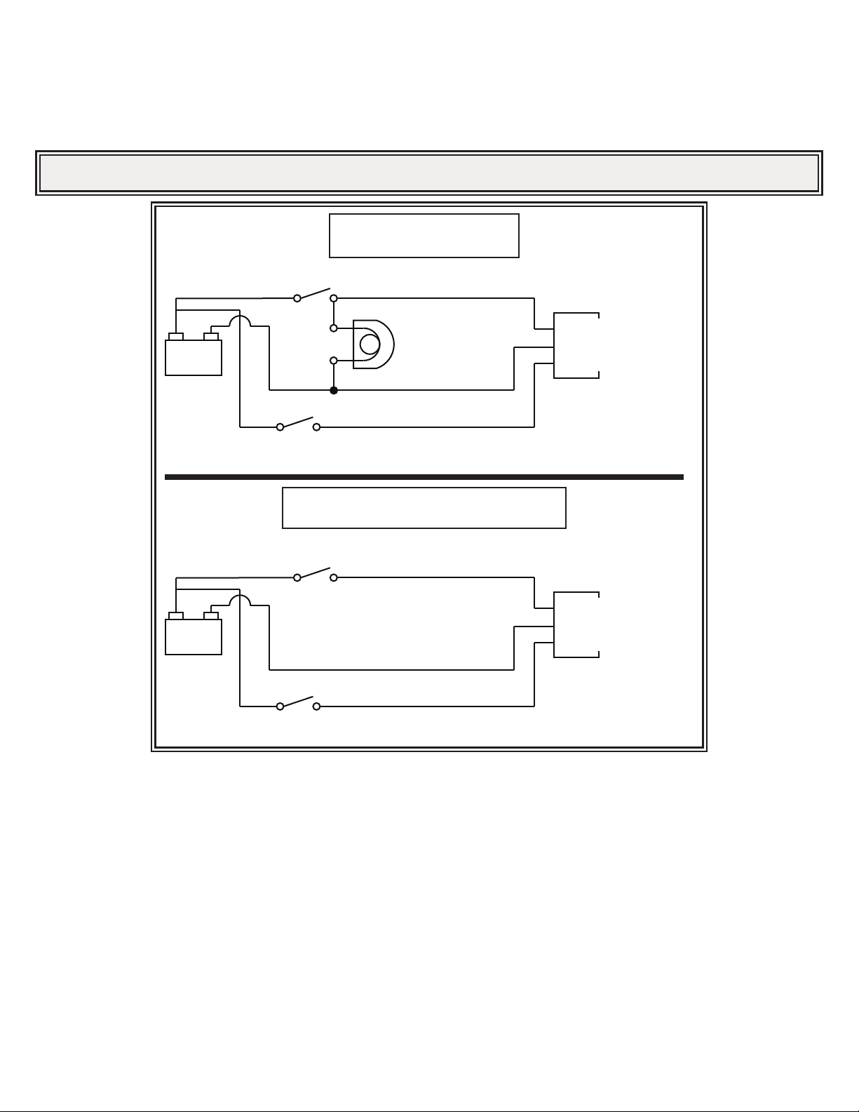
2. Seegure1.Usingthealarmhousingasatemplate,scribedrillpositionmarksthroughthemountingholesintheunit.Drillholesatthepositionmarks.
Recommended drill bit size- Q bit.
3. Secure the unit on the vehicle with a minimum of four user-supplied 5/16” bolts and locknuts, or bolts, lockwashers, and nuts.
IMPORTANT! Read all instructions before installing and using. Installer: This manual must be delivered to the end user.
WARNING!
Failure to install or use this product according to manufacturer’s recommendations may result in property damage, serious injury, and/
or death to those you are seeking to protect!
Do not install and/or operate this safety product unless you have read and understood the safety information
contained in this manual.
1. Proper installation combined with operator training in the use, care, and maintenance of emergency warning devices are essential to
ensure the safety of emergency personnel and the public.
2. Emergency warning devices often require high electrical voltages and/or currents. Exercise caution when working with live electrical
connections.
3. This product must be properly grounded. Inadequate grounding and/or shorting of electrical connections can cause high current arcing,
which can cause personal injury and/or severe vehicle damage, including re.
4. Proper placement and installation is vital to the performance of this warning device. Install this product so that output performance of
the system is maximized and the controls are placed within convenient reach of the operator so that they can operate the system without
losing eye contact with the roadway.
5. Do not install this product or route any wires in the deployment area of an air bag. Equipment mounted or located in an air bag
deployment area may reduce the eectiveness of the air bag or become a projectile that could cause serious personal injury or death.
Refer to the vehicle owner’s manual for the air bag deployment area. It is the responsibility of the user/operator to determine a suitable
mounting location ensuring the safety of all passengers inside the vehicle particularly avoiding areas of potential head impact.
6. It is the responsibility of the vehicle operator to ensure daily that all features of this product work correctly. In use, the vehicle operator
should ensure the projection of the warning signal is not blocked by vehicle components (i.e., open trunks or compartment doors),
people, vehicles or other obstructions.
7. The use of this or any other warning device does not ensure all drivers can or will observe or react to an emergency warning signal.
Never take the right-of-way for granted. It is the vehicle operator’s responsibility to be sure they can proceed safely before entering an
intersection, drive against trac, respond at a high rate of speed, or walk on or around trac lanes.
8. This equipment is intended for use by authorized personnel only. The user is responsible for understanding and obeying all laws
regarding emergency warning devices. Therefore, the user should check all applicable city, state, and federal laws and regulations. The
manufacturer assumes no liability for any loss resulting from the use of this warning device.
Installation and Operation Instructions
Auto Adjust 87-112 dB(A), 112 dB(A) Warble
12-24 Volt Back-Up Alarm
Selection and installation of an alarm should meet the requirements of local and regional governing bodies such as ISO, SAE, etc.
Installanalarmthatwillbeaudibleonthenoisiestjobsitethevehiclewillbeusedon.Groundguidanceshouldbeprovidedtoclearbacking
vehicles when the audibility of the alarm is in question. When installing an alarm product, be sure to verify that both sides of the mounting
surface are clear of anything that could be damaged. Place the back-up alarm so it will operate properly under adverse
conditions.Thelocationmustprovideprotectionfromimpactandpoorweatherconditionswhileallowingunobstructedsoundprojectionto
thetargethazardarea.DoNOTmountthealarmopeningfacingup.
The back-up alarm system must be inspected each workday at the beginning of each shift to ensure that it is audible, operating properly,
and securely attached to the vehicle. Inspect more often when: 1) The vehicle is operating in an adverse environment; 2) The vehicle is
operating in foul weather conditions; 3) The operator has reason to believe the alarm has been damaged or is not working properly; and/or
4) Increased background noise interferes with the ability of workers to recognize when the alarm is sounding.
Note: The back-up alarm should be used for REVERSING WARNING applications only. The alarm sound is generally
recognized as a warning for reversing vehicles/mobile equipment. Alarm products with dierent sound tones are available for non-
reversing applications.
Installation and Sound Level