ECD SmartDRY SD Series Manual instruction

ECD SmartDRY - Keeping products safe and reliable for peace of mind.
SD Series Dry Cabinets Setup and Operation Manual

ECD
World Headquarters
Electronic Controls Design, Inc.
4287-B S.E. International Way
Milwaukie, Oregon 97222-8825 U.S.A.
Telephone:
+1 800.323.4548
+1 503.659.6100
FAX:
+1 503.659.4422
Email:
Internet:
http://www.ecd.com
ECD Asia/Pacific
Singapore Office
Telephone:
+65 9692.6822
FAX:
+65 6241.9890
Email:
ecd.asia@ecd.com
ecd.china@ecdchina.cn
ECD Europe/Africa/Middle East
Mobile::
+48 512 659 100
Email:
ecd.europe@ecd.com
©2015-2018 ECD. All Rights Reserved. Printed in USA. US Products of ECD are covered by foreign and US Patents and Patents
Pending. Information in this publication supersedes all previously published information. This Publication may not be translated and/or
reproduced or stored in data retrieval system, or transmitted in any form or by any means without the express written permission of
ECD. Specification and price change privileges reserved.
The trapezoidal ECD logo® is a registered trademark of ECD. SmartDRY™ is a trademarked by ECD.
While every precaution has been taken in the preparation of this document, ECD assumes no responsibility for errors or omissions, or
for damages resulting from the use of information contained in this document or from the use of programs and source code that may
accompany it. In no event shall ECD be liable for any loss of profit or any other commercial damage caused or alleged to have been
caused directly or indirectly by this document.

DECLARATION OF CONFORMITY
Electronic Controls Design, Inc.
4287-B S.E. International Way
Milwaukie, Oregon U.S.A. 97222-8825
(503) 659-6100 / (800) 323-4548
FAX: (503) 659-4422
Declaration of Conformity
Product:
SmartDRY™ SD-10 & SD-10SB
Part Number:
E55-7310-30/35
E58-7310-60/65
SmartDRY™ SD-30 & SD-10SB
E55-7330-30/35
E57-7339-30/35
SmartDRY™ SD-48F & SD-30XD
E55-7483-30/35
E57-7489-30/35
The undersigned hereby declares, on behalf of the ECD Inc., that the above-referenced product, to which this declara-
tion relates, is in conformity with the provisions of:
SAFTEY:
IEC 61010-1 “Safety requirements for electrical equipment for measurement, control, and laboratory use - Part 1: General require-
ments”
EMISSIONS:
EN 61000-3-2:2014 “Electromagnetic Compatibility (EMC) - Limits For Harmonic Current Emissions …”
EN 61000-3-3:2013 “Electromagnetic Compatibility (EMC) - Limitation of voltage changes, voltage fluctuations and flicker …”
EN 61000-6-4:2007+A1:2011 Class A “Electromagnetic compatibility (EMC) - Emission standard for industrial
environments”
FCC 15.107:2015 Class A “Conducted Limits”
FCC 15.109(g):2015 Class A “Radiated emission limits”
ICES-003:2012 Class A “Information Technology Equipment (ITE) – Limits”
IMMUNITY:
EN 61000-6-1:2007 “Electromagnetic Compatibility (EMC). Immunity for residential, commercial and light-industrial environments”
The Technical Construction File required by this Directive is maintained at the corporate headquarters of ECD, Inc.
Name:
Paul Austen
Position:
Senior Project Engineer
Signature:
Date:
August, 2015

TABLE OF CONTENTS
1.0 Introduction ......................................................................................................................................................................................... 7
2.0 Receiving and Inspection .....................................................................................................................................................................8
2.1 Inspection......................................................................................................................................................................................... 8
2.2 Loss or Damage................................................................................................................................................................................ 8
2.3 Shipping Materials ...........................................................................................................................................................................8
2.4 Return Shipment ..............................................................................................................................................................................8
2.5 Accessories....................................................................................................................................................................................... 8
3.0 Graphic Symbols .................................................................................................................................................................................. 9
4.0 Operators Safety Information ............................................................................................................................................................12
5.0 Setup & Installation............................................................................................................................................................................ 13
5.1 Power Source ................................................................................................................................................................................. 13
5.2 Location.......................................................................................................................................................................................... 14
5.3 Lifting / Handling............................................................................................................................................................................15
5.4 Leveling .......................................................................................................................................................................................... 15
5.5 Shelf Placement ............................................................................................................................................................................. 16
6.0 Control Panel .....................................................................................................................................................................................18
6.1 Main Display................................................................................................................................................................................... 18
6.1.1 Current RH ..............................................................................................................................................................................19
6.1.2 Current Temperature .............................................................................................................................................................. 19
6.1.3 Status indicators ..................................................................................................................................................................... 20
6.1.4 Count Down Timer .................................................................................................................................................................. 22
6.1.5 Graph Display.......................................................................................................................................................................... 23
6.1.6 Menu System .......................................................................................................................................................................... 23
6.2 OK................................................................................................................................................................................................... 24
6.3 Down Arrow ................................................................................................................................................................................... 24
6.4 Up Arrow........................................................................................................................................................................................ 24
6.5 Interior Lighting.............................................................................................................................................................................. 25
6.6 Alarm Mute .................................................................................................................................................................................... 25
6.7 Alarm Cancel ..................................................................................................................................................................................26
6.8 ESD Protection ...............................................................................................................................................................................26
7.0 Network Dashboard........................................................................................................................................................................... 27
7.1 Dashboard...................................................................................................................................................................................... 27
7.2 Settings ..........................................................................................................................................................................................29
7.3 Setup .............................................................................................................................................................................................. 30
7.4 Viewing initial SmartDRY™ data..................................................................................................................................................... 30

SD Series Dry Cabinets Setup and Operation Manual | A55-7379-00 Rev: 2.0.0 Page 5
8.0 Quick Start..........................................................................................................................................................................................31
8.1 Safety and Installation ................................................................................................................................................................... 31
8.2 Location.......................................................................................................................................................................................... 31
8.3 Shelf Configuration ........................................................................................................................................................................ 32
8.4 Power .............................................................................................................................................................................................33
8.5 Time settings.................................................................................................................................................................................. 34
8.6 Clear History................................................................................................................................................................................... 35
9.0 Operation ........................................................................................................................................................................................... 36
9.1 SmartDRY™ Menu System .............................................................................................................................................................37
9.1.1 RH Setpoint ............................................................................................................................................................................. 38
9.1.2 Alarms (SmartDRY™)............................................................................................................................................................... 39
9.2 SmartBAKE™ Menu (Optional)....................................................................................................................................................... 41
9.2.1 J-STD-033 ................................................................................................................................................................................42
9.2.2 Manual Bake ...........................................................................................................................................................................43
9.2.3 Alarms (SmartBAKE™) .............................................................................................................................................................44
9.3 Other Settings ................................................................................................................................................................................ 46
9.3.1 Units ........................................................................................................................................................................................ 46
9.3.2 Date/Time ............................................................................................................................................................................... 47
9.3.3 Data Logging ........................................................................................................................................................................... 48
9.3.4 Network .................................................................................................................................................................................. 49
9.3.5 Sensor ..................................................................................................................................................................................... 50
9.3.6 Lighting.................................................................................................................................................................................... 51
9.3.7 Passcode .................................................................................................................................................................................52
9.4 Help................................................................................................................................................................................................ 53
9.5 Graph ............................................................................................................................................................................................. 54
10.0 Equipment Maintenance .................................................................................................................................................................55
10.1 Cleaning ....................................................................................................................................................................................... 55
10.2 ECD SmartDRY™ Humidity and Temperature Sensor .................................................................................................................. 56
10.3 Clock battery ................................................................................................................................................................................ 57
10.4 SmartDRY™ Dryer ........................................................................................................................................................................58
10.5 Power Board ................................................................................................................................................................................65
10.6 RH/Temperature Probe ............................................................................................................................................................... 69
10.7 SmartBAKE™ Heater..................................................................................................................................................................... 70

SD Series Dry Cabinets Setup and Operation Manual | A55-7379-00 Rev: 2.0.0 Page 6
11.0 Service and Troubleshooting ........................................................................................................................................................... 72
11.1 Main Display is black:................................................................................................................................................................... 72
11.2 RH set point is not achieved: ....................................................................................................................................................... 73
11.3 Bake Temperature set point is not achieved: ..............................................................................................................................74
11.4 System Alerts ...............................................................................................................................................................................75
11.5 Updating SmartDRY™ SD Series Dry Cabinets Firmware & Network Dashboard ........................................................................ 76
11.6 SYSTEM RESET.............................................................................................................................................................................. 77
11.7 Contact Information.....................................................................................................................................................................80
Appendix ..................................................................................................................................................................................................81
Appendix A: Parts List ..........................................................................................................................................................................81
Appendix B: Specifications................................................................................................................................................................... 82
Appendix C: Schematic ........................................................................................................................................................................85
Appendix D: Useful Tables ...................................................................................................................................................................87
Appendix E: Gossary ............................................................................................................................................................................ 88
Appendix F: Network ...........................................................................................................................................................................96

SD Series Dry Cabinets Setup and Operation Manual | A55-7379-00 Rev: 2.0.0 Page 7
1.0 INTRODUCTION
Thank you for purchasing an ECD SmartDRY™ SD Series Dry Cabinets. We know that in today’s competitive
market place, customers have several choices when purchasing a dry storage cabinet. Our continued reputa-
tion as a leading supplier of process and measurements tools depends of each customer’s continued satisfac-
tion. ECD, Inc. stands behind our products and wants to let you know we are here if you need us.
Before you use the SmartDRY™ Cabinet, read this entire manual carefully to understand how to install, oper-
ate, and maintain the unit in a safe manner. Your satisfaction with the unit will be maximized as you read
about its safety and operational features.
Keep this manual on-hand so it can be used by all operators of the unit. Be sure all operators of the unit are
given appropriate training before you put the unit in service.
This Setup and Operation Manual explains how to install use ECD dry storage cabinets and Network Dash-
board.
This Setup and Operation Manual is written for users of varied experience. If a section covers information you
already know, feel free to skip to the next section.
HARDWARE PORTIONS OF THIS MANUAL ARE WRITTEN TO REFLECT THE FOLLOWING FIRMWARE
VERSION 00.01.09 AND HIGHER.
THE NETWORK DASHBOARD PORTIONS REFLECT VERSION(S) 1.06 AND HIGHER.

SD Series Dry Cabinets Setup and Operation Manual | A55-7379-00 Rev: 2.0.0 Page 8
2.0 RECEIVING AND INSPECTION
IMPORTANT: READ THIS MANUAL IMMEDIATELY.
Your satisfaction and safety require a complete understanding of the SmartDRY™ Cabinet, including its proper
function and operation. Be sure operators are given adequate training before attempting to put the cabinet in
service.
This equipment must be used only for its intended application; any alterations or modifications
will void your warranty.
2.1 INSPECTION
The carrier, when accepting shipment, also accepts responsibility for safe delivery and is liable for loss or dam-
age claims. On delivery, inspect for visible exterior damage. Note and describe on the freight bill any damage
found and enter your claim on the form supplied by the carrier.
2.2 LOSS OR DAMAGE
Inspect for concealed loss or damage on the cabinet itself, both interior and exterior. If any, the carrier will
arrange for official inspection to substantiate your claim.
2.3 SHIPPING MATERIALS
Save the shipping crate until you are sure the unit has been delivered in good condition.
2.4 RETURN SHIPMENT
If for any reason you must return the unit, contact ECD for a Return Materials Authorization (RMA). Be pre-
pared to supply the Model Number and Serial number located on the Serial number label when requesting an
RMA. Please refer to 11.0 Service & Troubleshooting for information for contact information or visit
www.ecd.com.
2.5 ACCESSORIES
Verify all of the equipment indicated on the packing list is included with the unit. Carefully check all packaging
before discarding.

SD Series Dry Cabinets Setup and Operation Manual | A55-7379-00 Rev: 2.0.0 Page 9
3.0 GRAPHIC SYMBOLS
The SmartDRY™ Cabinet and this Setup and Operation Manual uses graphic symbols which help identify at a
glance several Dangers, warnings, functions, as well as indicate the status of the cabinet:
Product Symbols:
Warning: Whenever this internationally recognized symbol is used on the product, additional infor-
mation concerning that particular feature or function appears in the Setup and Operation Manual.
Waste Electrical and Electronic Equipment (WEEE). Unit should be recycled; Do not disposed of in
land-fill.
Warning: Warm surface or vent. Keep clear; do not touch or block.
Electro Static Discharge (ESD) protective wrist strap connection point.
Ground point.
Warning: Electrical Shock / Electrocution Hazard. Do not remove this cover.

SD Series Dry Cabinets Setup and Operation Manual | A55-7379-00 Rev: 2.0.0 Page 10
Control Panel Symbols:
Displays Main Menu.
Animated symbol that indicates Drying in process. Static indicates this dryer is on line.
Animated symbol that indicates Regeneration in process. Static indicates awaiting regeneration.
Animated symbol that indicates heat is being applied. Static indicates Bake cycle initiated.
Displays a graph (rH or Temperature)
Moves increments a user entered value.
Approves a user set value for the the current highlighted menu item.
Moves decrements a user entered value.
Mutes the buzzer for all current alarms.
Press to turn on the interior lights.
Indicates that the cabinet is connected to a network.
SD Series Dry Cabinets Setup and Operation Manual | A55-7379-00 Rev: 2.0.0 Page 11
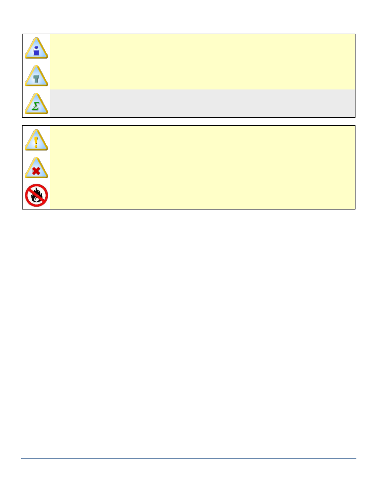
Setup and Operation Manual Symbols:
Informs the user that the note includes important information.
Informs the user that the note includes a handy tip.
Informs the user of an equation used.
Informs the user that the note identifies conditions or practices that could result in damage to the
equipment.
Informs the user that the note identifies conditions or practices that could result in personal injury
or damage to property other than the equipment.
Danger: Not for use with explosive, combustible, or flammable materials.

SD Series Dry Cabinets Setup and Operation Manual | A55-7379-00 Rev: 2.0.0 Page 12
4.0 OPERATORS SAFETY INFORMATION
The safety information in this section is for the benefit of operating personnel. Warnings and Cautions will also
be found throughout the manual where they apply.
The SmartDRY™ SD Series Dry Cabinets are ETL listed and self-declared to meet the requirements
of CE for the storage of components at low relative humidity and temperatures. It is not intended
for the storage of flammable, volatile or combustible materials. These units have been tested per
the requirements indicated in topic: Declaration of Conformity.
Hardware changes or modifications to the SmartDRY™ SD Series Dry Cabinets or components are not expressly
approved by ECD and could void the warranty.
THE WARRANTY WILL NOT COVER DAMAGE CAUSED BY NEGLECT OR ABUSE OF ANY ECD PROD-
UCTS. TO MAINTAIN THE SAFETY FEATURES INCORPORATED, OPERATION MUST BE IN STRICT
COMPLIANCE WITH THE REQUIREMENTS SPECIFIED HEREIN.
The SmartDRY™ SD Series Dry Cabinets and the recommended accessories have been designed and tested to
meet strict safety requirements. For continued safe operation, always follow these basic safety precautions:
•Read this entire Setup and Operation Manual before using.
•Be sure you follow any city, county, or other ordinances in your area regarding the use of this cabinet.
•Use only approved accessories.
•Do not modify system components. Any alterations or modifications to your SmartDRY™ SD Series Dry Cabinets may be
dangerous and will void your warranty.
•Always plug the cabinet power cord into a grounded electrical outlet that conforms to national and local electrical codes. If
the cabinet is not grounded, it can conduct electricity and may cause serious injury.
•Do not connect the unit to a power source of any other voltage or frequency beyond the range stated in the power rating
on the cabinet’s serial number plate.
•Do not modify the power cord provided with the unit.
•Avoid damaging the power cord. Do not bend it excessively, step on it, place heavy objects on it. A damaged cord can eas-
ily become a shock or fire hazard. Never use a power cord after it has become damaged.
•Do not position the equipment in such a manner as to make it difficult to disconnect power cord.
•Do not attempt to move the unit while in operation.
•THIS IS NOT AN EXPLOSION PROOF CABINET. Do not place or use explosive, combustible, or flammable materials in the
cabinet.
•Do not store liquids of any kind. Evaporation of any liquids, other than water, may damage the RH sensor.
•Disconnect the cabinet from the electrical power source before removal of any covers or panels.
•Repairs or component replacements should be done by trained service personnel.
•This cabinet is NOT suitable for use in Class I, II, or III locations as defined in the National Electric Code of the United States
of America, NFPA 70.
•Do not block Cabinet Dryer units.
•Do not touch Dryer unit vent area when in regeneration cycle.
SD Series Dry Cabinets Setup and Operation Manual | A55-7379-00 Rev: 2.0.0 Page 13
5.0 SETUP & INSTALLATION
The installation of the SmartDRY™ Cabinet may be performed by the end user. Local, city, county, or other ju-
risdictions may govern the use of this equipment. If you have any questions about local requirements, please
contact the appropriate local agency.
The SmartDRY™ Cabinet is intended for indoor use only, at room temperatures between 15°C and 35°C, at no
greater than 80% relative humidity (at 25°C) and <2, 000 meters (6,561ft) elevation.
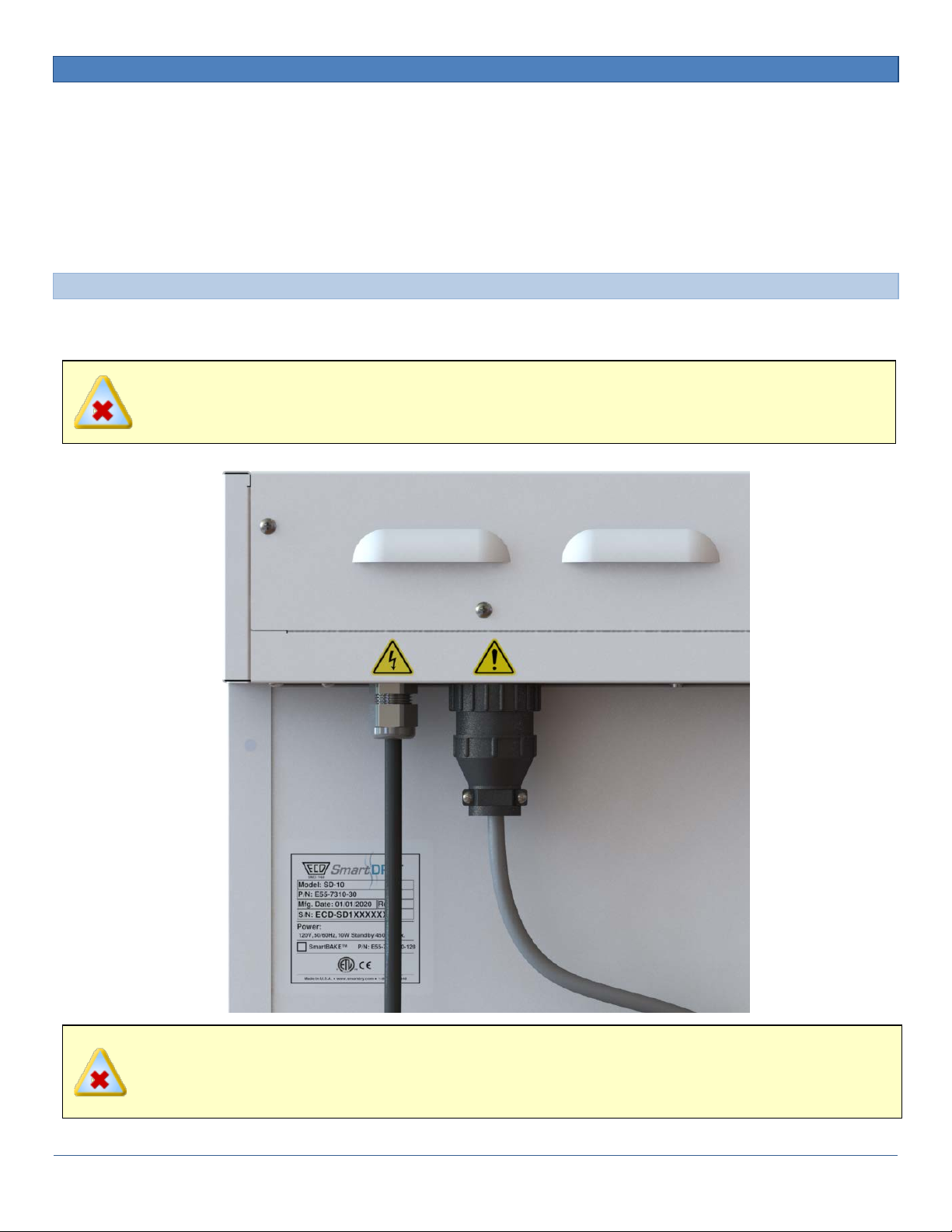
5.1 POWER SOURCE
The power requirements are listed on the cabinet serial number label. The supply voltage should not vary
more than 10%.
POSITION THE UNIT TO ALLOW USER ACCESS TO THE POWER CORD FOR MAINS DISCONNECT.
PLUG THE UNIT INTO A PROPERLY GROUNDED AND RATED RECEPTACLE OF THE CORRECT TYPE.
THE VOLTAGE AT THE RECEPTACLE SHOULD NOT VARY MORE THAN 10% FROM THE LISTED RAT-
ING.
SD Series Dry Cabinets Setup and Operation Manual | A55-7379-00 Rev: 2.0.0 Page 14
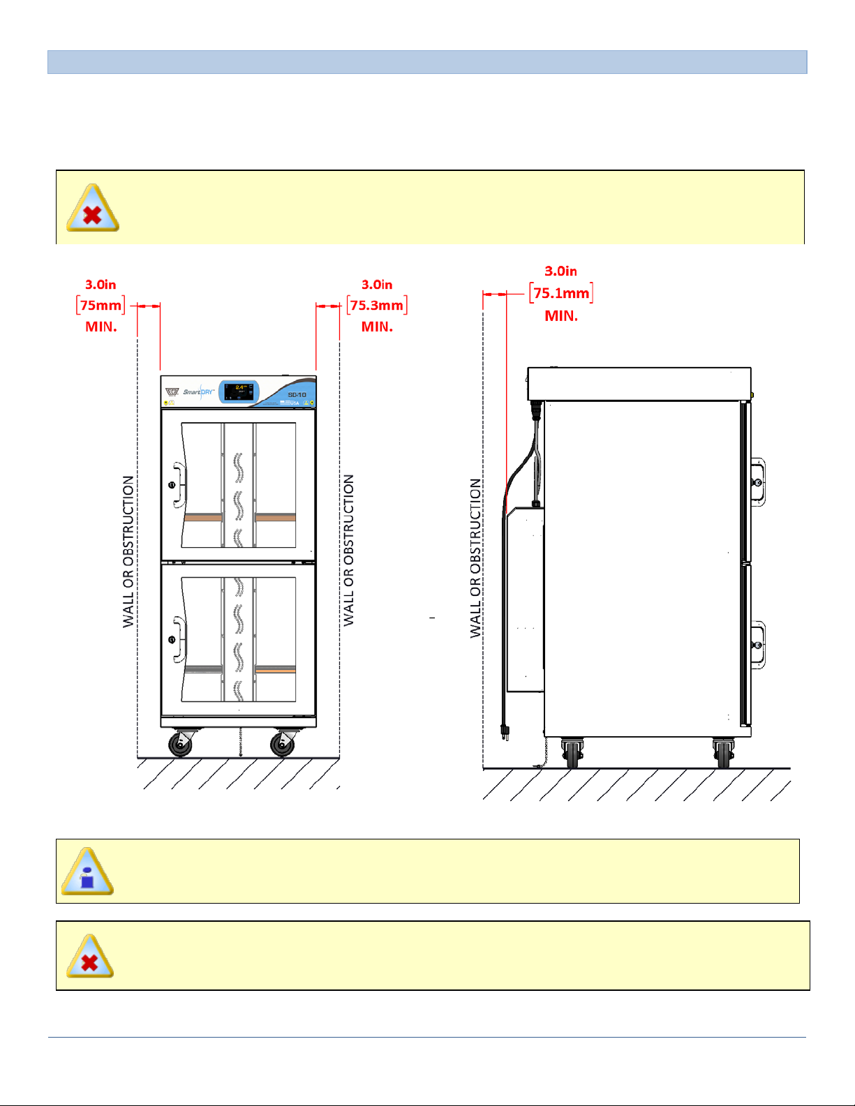
5.2 LOCATION
When selecting a site for the cabinet, consider conditions which may affect performance, such as heat from
radiators, ovens, production equipment, etc. Avoid direct sun, fast-moving air currents, heating/cooling ducts
etc. To ensure air circulation, allow a minimum of 75 mm (3”) between the unit and any walls or partitions
which might obstruct free air flow.
POSITION THE UNIT TO ALLOW USER ACCESS TO THE POWER CORD FOR MAINS DISCONNECT.
MODEL SD-10 SHOWN AS AN EXAMPLE. THE MINIMUM DISTANCE SPECIFICATION APPLIES TO
ALL SmartDRY™ CABINET MODELS.
TO AVOID OVER HEATING OR RISK OF FIRE, DO NOT BLOCK THE DRYER UNIT VENTS.

SD Series Dry Cabinets Setup and Operation Manual | A55-7379-00 Rev: 2.0.0 Page 15
5.3 LIFTING / HANDLING
SD Series Dry Cabinets are heavy and care should be taken to use appropriate lifting devices that are suffi-
ciently rated for the load. SD Series Dry Cabinets should only be lifted from their bottom surfaces. Door han-
dles, enclosures and cabinet overhangs are not adequate for lifting or stabilization. The cabinet should be
completely restrained from tipping during lifting or transport. Shelves should be removed and doors locked in
the closed position before and during transfer to prevent shifting and damage.
5.4 LEVELING
The cabinet should be placed on a level a solid, level surface. The wheels should be locked once in place to
prevent movement.

SD Series Dry Cabinets Setup and Operation Manual | A55-7379-00 Rev: 2.0.0 Page 16
5.5 SHELF PLACEMENT
Cabinet Shelves are held in place on each side by a shelf support that slips into pre-cut slots. The shelf sup-
ports are symmetrical and can be used to support either the left or right side of the shelf. Slots are pre-cut to
prevent blocking of air vents and LED lighting in addition to fitting most common parts bins, boxes and reels;
place as needed to meet your needs.
To install:
1) Open an cabinet door.
2) Insert the shelf supports into the desired location of the shelf tracks making sure they are both on the
same track notch and secure.

SD Series Dry Cabinets Setup and Operation Manual | A55-7379-00 Rev: 2.0.0 Page 17
3) Tilt the shelf at a slight angle, and insert through the cabinet door and place on the installed shelf sup-
ports.
TO AVOID DAMAGE TO THE CABINET LED'S OR THE CABINET, WHEN REMOVING THE SHELVING
FROM IT MUST BE TILTED ENOUGH TO AVOID CONTACT WITH ANY OBSTACLE.
SD Series Dry Cabinets Setup and Operation Manual | A55-7379-00 Rev: 2.0.0 Page 18
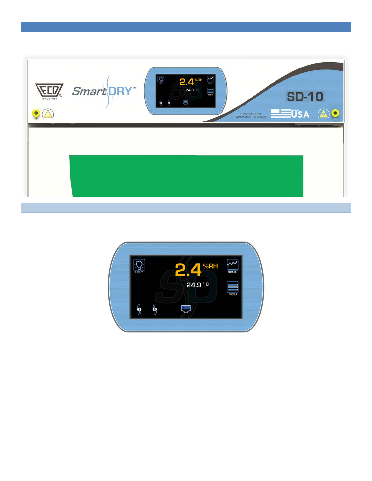
6.0 CONTROL PANEL
6.1 MAIN DISPLAY
Displays current conditions and allow access to all programmable functions. The contents of this display
change depending if you are in SmartDRY™ or SmartBAKE™ mode.

SD Series Dry Cabinets Setup and Operation Manual | A55-7379-00 Rev: 2.0.0 Page 19
6.1.1 CURRENT RH
Displays the current RH measurement. (When in the optional SmartBAKE™ mode this displays the current
Temperature.)
6.1.2 CURRENT TEMPERATURE
Displays the current Temperature measurement. (When in the optional SmartBAKE™ mode this displays the
current RH.)

SD Series Dry Cabinets Setup and Operation Manual | A55-7379-00 Rev: 2.0.0 Page 20
6.1.3 STATUS INDICATORS
Indicates status of each Dryer Module.
Drying Symbol
Animated to indicate the dryer is actively drying the interior of the cabinet. Static to indicate that it is currently
on line for drying.
Other manuals for SmartDRY SD Series
2
This manual suits for next models
17
Table of contents
Other ECD Dryer manuals

Popular Dryer manuals by other brands


Whirlpool
Whirlpool WGD9250WR - Duet Cranberry - Gas Dryer installation instructions

Esatto
Esatto EVD7 user manual

Hoover
Hoover Vented Tumble Dryer Instruction book

GE
GE DCVH480EK Dimensions and installation information

Whirlpool
Whirlpool 8527902 installation instructions

GE
GE DNCJ440EB Technical service guide