GE DNCJ440EB How to use

GE Commercial SmartCard Reader Dryers
GE Commercial Laundry
TECHNICAL SERVICE GUIDE
MODEL SERIES
ELECTRIC AND GAS DRYERS
DNCJ440EB/DNCJ440GB (Bridgepoint Reader)
DNCK440EB/DNCK440GB (ESD Reader)
Pub 31-15526 06/02


1
Features
Installation Highlights
Control Panel Field Service Mode
2
3
4
10
12
13
Table of Contents
15
16
18
26
Rating Plate/Service Information
Schematic/Wiring Diagram
Parts Pages/Exploded Views
Warranty
Troubleshooting flowcharts
Control Board Layout
Basic Disassembly

2
RATING PLATE AND SERVICE INFORMATION LOCATION
Connector Cable
Remove 4 Screws
Card Reader
Mini Manual
GE Commercial Gas and Electric Dryers have a
Rating Plate located on the front inside door
opening at the top right. It lists the Model Number,
UL listings, and individual product serial number.
You can see the rating plate by simply opening the
dryer door.
CAUTION!: Always disconnect appliance from
power prior to servicing to avoid shock hazard.
A mini-manual is provided inside the control panel
and has basic service information. On the back
side of the mini-manual is the product schematic,
which is valuable in troubleshooting any problems.
Resistances, voltages, and wiring colors are
shown and can be used with a volt-ohm meter to
check circuitry, and components.
The illustrations on the right provide graphic
information on how to access the mini-manual by
removing (4) T-20H Torx screws from the top of
the control panel and rolling it over on the top of
the dryer. The second illustration shows mini-
manual location, as well as SmartCard reader
access.
Remove 4 Screws
Dual Seven Segment
Display (DSSD)
Card
Reader
INSERTCARD
INSERTCARD
$
CARDV
CARDV
ALUE
CLOTHES CARE SELECTION
COTTON
SYNTHETIC
PERM
PRESS
DELICATES
START
FABRIC HEAT SETTING
COTTONS..................... HIGH HEAT
PERM PRESS............... HIGH HEAT
SYNTHETIC KNITS......MED HEAT
DELICATES....................LOWHEAT
EST
.TIME
REMAINING
DOOROPENDRYINGCOOLDOWN
KNITS
WITHCOOLDOWN

3
FEATURES
GE Commercial Laundry clothes dryers
DNCJ440E/GA0W (equipped with a BridgePoint
Card reader), and DNCK440E/GA0W (equipped
with ESD Card reader) provides new technology
and flexibility to the proven GE dryer platform.
These two systems provide the Commercial Laun-
dry operators with the ability to control pricing,
usage, and a multitude of functions, along with
audit functions for successful operation control
including activity reports.
Laundry Logic Management Software provides full
audit/transactional records displayed in 30 reports.
Theft and vandalism is greatly reduced by removing
cash from the dryer. Collection activities are re-
duced increasing productivity.
End users benefit because all the information is
stored on a card that retains all necessary usage
information. In both units a central reader station is
located at the Laundry site, the user inserts money
and the card is encoded to provide the service level
required by the user. The card is then inserted into
the dryer reader port, and the cycle is selected by
the user and the card is adjusted to charge for
usage.
The user can then replenish their card for the next
usage at the ESD Value Transfer Machine or VTM,
for BridgePoint the SmartLaundryTM Cash2Card
Value-Add Terminal (for all options contact
BridgePoint at 1-800-562-5875, or ESD at 1-800-
523-1510, ext. 104) for more information on termi-
nals. The product warranty specifies that the Card
Reader is serviced by the readers’ original equip-
ment manufacture, readers are available and listed
as GE Part #’s for the following models:
DNCJ440E/G BRIDGEPOINT READER
-
WH12X10217, and
DNCK440E/G
ESD READER
-
WH12X10218.
The Keypad electronic Card Reader models have
Field Service Diagnostics mode, which records
certain faults and retains them for review by the
servicer. A cycle progession mode can also be
enabled to make a check of normal component
operation.
The durable electronic controls replace timers and
analog buttons with membrane keypads, and
functions with printed PC board, onboard trans-
former and programmed logic.

4
INSTALLATION HIGHLIGHTS
It is IMPORTANT to read and understand the
complete installation instructions for your GAS or
ELECTRIC Commercial SmartCard dryers. The
installation highlights will cover exhausting tips,
gas line installation tips, and electric dryer hookup
requirements. Full comprehensive installation
instructions for your particular model is shipped
with every dryer. FOR QUESTIONS ON INSTAL-
LATION, CALL: 1-800-626-2003.
A good installation makes for good performance
and consist of the following steps as outlined in
your installation instruction shipped with the
appliance.
STEP 1- Prepare the area and exhaust for instal-
lation of new dryer.
STEP 2- Check and make sure the existing exter-
nal exhaust is clean and meeted the installation
specifications.
STEP 3- Remove the foam shipping pads.
STEP 4- Move the dryer to the desired location.
STEP 5- Connect powersupply.
STEP 6- Connect the external exhaust.
STEP 7- Level your dryer.
STEP 8- Check the operation of the power supply
and venting.Check the installation instruction for
special installation for Alcove or Closet, Bathroom
or Bedroom, Mobile or Manufactured Home, for
side and bottom exhaust. They are completely
covered in the product installation instructions.
FOR YOUR SAFETY:
WARNING
Use only rigid metal or flexible metal 4” diameter
ductwork for exhausting to the outdoors. Never
use plastic or other combustible, easy to puncture
ductwork.
This appliance must be properly grounded and
installed per the appliance installation instructions
shipped with every appliance.
Do not install or store appliance in an area where
it will be exposed to water and/or weather.
Install the dryer where the temperature is above
500F. for correct operation of dryer controls.
!
EXHAUSTING:
The MOST IMPORTANT element to good perfor-
mance is VENTING the dryer. With out sufficient
airflow dry times will be longer and linting will
develop.
If you are installing in an existing wall duct make
sure that you make sure the internal duct opening
is clear and that the hood damper opens and
closes freely.
Minimum clearance to combustible surfaces and
for air openings are: 0 in. clearance both sides and
1 in. rear. Consideration must be given to provide
adequate clearance for installation and service.
REMOVE LINT FROM WALL EXHAUST
PREPARING FOR INSTALLATION OF NEW
DRYER

5
EXHAUSTING:
NOTE: The correct exhaust installation is
YOUR RESPONSIBILITY.
Problems due to incorrect installation are NOT
covered in the warranty.
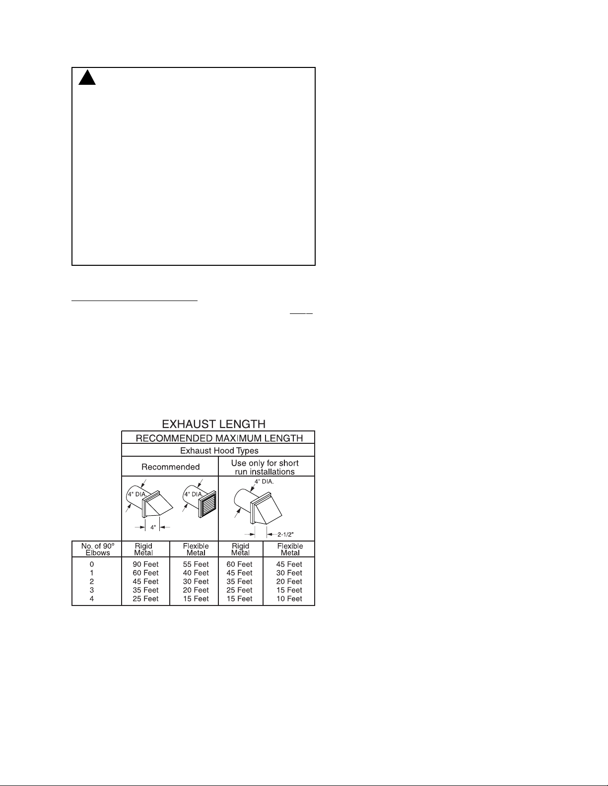
The MAXIMUM ALLOWABLE length of the ex-
haust system depends upon the type of duct,
number of turns, the type of exhaust hood (wall
cap), and all conditions noted below. Both rigid
and flexible metal are shown in the chart below.
EXHAUST SYSTEM CHECK LIST
HOOD OR WALL CAP
-Terminate in a manner to prevent back drafts or
entry of birds or other wildlife.
-Termination should present minimal resistance to
the exhaust air flow and should require little or no
maintenance to prevent clogging.
-NEVER install a screen in or over the exhaust
duct. This could cause lint build up.
-Wall caps must be installed at least 12 in. above
ground level or any other obstructions with the
opening pointing down.
-If roof vents or louvered plenums are used, they
must be equivalent to a 4-in. dampened wall cap
in regard to resistance to air flow, prevention of
back drafts, and maintenance requied to prevent
clogging.
SEPARATION OF TURNS:
-For best performance, separate all turns with at
least 4 ft. of straight duct., including distance
between last turn and exhaust hood.
TURNS OTHER THAN 900
-One turn of 450or less may be ignored
-Two 450 turns should be treated as one 900 turn.
-Each turn over 450 shold be treated as one 900
turn.
SEALING OF JOINTS
-All joints should be tight to avoid leaks. The male
lend of each section of duct must point away from
dryer.
-Do not assemble the ductwork with fasterners
that extend into the duct. They will serve to collect
lint.
-Duct joints can be made air tight by wrapping the
overlapped joints with duct tape.
-Horizontal runs should slope down toward the
outdoors 1/2 in. per foot.
INSULATION:
Duct work that runs through an unheated area or
is near air conditioning, should be insulated to
reduce condensation and lint build-up.
WARNING! - TO REDUCE THE RISK
OF FIRE OR PERSONAL INJURY:
-Exhausting the dryer to the outdoors is strongly
recommended to prevent large amounts of moisture
from being blown into the room.
-Use only metal duct.
-Do not terminate exhaust in a chimney, any gas vent,
under an enclosed door (crawl space), or into an
attic. The accumulated lint could create a fire
hazard.
-Provide an access for inspection and cleaning of the
exhaust system, especially at turns. Inspect and
clean at least once a year.
-Never terminate the exhaust into a common duct with
kitchen exhaust. A combination of lint and grease
could create a fire hazard.
-Do not obstruct incoming or exhausted air.
!

6
INSTALLATION HIGHLIGHTS/VENTING
The dryer comes ready for rear exhausting. Refer
to your installation instructions if space is limited
and you need to exhaust from the sides or bottom
of cabinet.
An example of standard rear exhaust vented at
floor level is shown below.

7
INSTALLATION HIGHLIGHTS/LEVELING
It is also important that you take the time to level
the dryer. It helps to remove vibration, “walking”,
and improves clothing turn over rate for improved
drying. Illustration below show the correct method
to level the dryer.
INSTALLATION HIGHLIGHTS/ELECTRIC 4
WIRE HOOK UP:
WARNING- TO REDUCE THE RISK OF FIRE,
ELECTRICAL SHOCK AND PERSONAL INJURY:
-DO NOT USE AN EXTENSION CORD OR AN
ADAPTER PLUG WITH THIS APPLIANCE.
Dryer must be electrically grounded in accordance
with local codes and ordinances, or in absence of
local code, in accordance with NATIONAL ELEC-
TRICAL CODE. ANSI/NFPA NO. 70.
!
INSTALLATION HIGHLIGHTS/
ELECTRICAL REQUIREMENTS
(ELECTRIC DRYER)
This dryer must be connected to an individual
branch circuit, protected by the required time-
delay fuses or circuit breakers. A four or three
wire, single phase, 120/240V or 120/208V, 60
Hz, 30 amp circuit is required.
If the electric supply doesn’t meet the above
specifications, then call a licensed electrician.
GROUNDING INSTRUCTIONS
This dryer must be connected to a grounded
metal, permanent wiring system, or an equip-
ment-grounding conductor must be run with the
circuit conductor and connected to the equip-
ment grounding terminal on the appliance.
ELECTRIC 4-WIRE HOOK UP:
1. Turn off the circuit breaker (s) (30 amp) or
remove the dryer’s circuit fuse at the electrical
box.
2. Be sure the dryer cord is unplugged from the
wall receptacle.
3. Remove the power cord cover located at the
back.

8
INSTALLATION HIGHLIGHTS/ELECTRIC
(CONT’)
4. Remove and discard ground strap. Keep the
green ground screw for step 7.
5. Install 3/4” UL recognized strain relief to power
cord entry hole. Bring power cord through strain
relief.
6. Connect power cord as follows:
A. Connect the 2 hot lines to the outer
screws of the terminal block (marked L1
and L2).
B. Connect the neutral (white) line to the
center of the terminal (marked N).
7. Attach ground wire of power cord with the green
ground screw (hole above strain relief bracket).
tighten all terminal block screws (3) completely.
8. Properly secure power cord to strain relief.
9 Reinstall cover.
WARNING: NEVER LEAVE THE
COVER OFF THE TERMINAL BLOCK.
!
ELECTRIC 3 WIRE HOOK UP:
1. Turn off the circuit breaker (s) (30 amp) or
remove the dryer’s circuit fuse at the electrical
box.
2. Be sure the dryer cord is unplugged from the
wall receptacle.
3. Remove the power cord cover located at the
back.
4. Install 3/4” UL recognized strain relief to power
cord entry hole. Bring power cord through strain
relief.
5. Connect power cord as follows:
A. Connect the 2 hot lines to the outer
screws of the terminal block (marked L1
and L2).
B. Connect the neutral (white) line to the
center of the terminal (marked N).
6. Be sure ground strap is connected to neutral
(center) terminal of block and to green ground
screw on cabinet rear. Tighten all terminal block
screws (3) completely.
7. Properly secure power cord to strain relief.
8. Reinstall the cover.
WARNING: NEVER LEAVE THE
COVER OFF THE TERMINAL BLOCK.
!
ELECTRIC 3 WIRE HOOKUP

9
INSTALLATION HIGHLIGHTS/GAS
TIGHTEN ALL CONNECTIONS USING TWO
ADJUSTABLE WRENCHES
GAS SUPPLY
A 1/8-in. National Pipe Taper thread plugged
tapping, accessible for test gauge connection,
must be installed immediately upstream for the
gas supply connection to the dryer. Contact your
local gas utility should lyou have questions on the
installation of the plugged tapping.
Supply line is to be 1/2-in. rigid pipe and equipped
with an accessible shut-off within 6 ft. of, and in
the same room with, the dryer.
Use pipe thread sealer compound appropriate for
natural or LP gas or use Teflon Tape.
Connect flexible metal connector to dryer and gas
supply.
Open shut-off valve, use commercial leak detector
fluid and check for leaks. Reinstall if leaks are
detected.
USE COMMERCIAL
LEAK TEST FLUID
TO CHECK FOR
LEAKS

10
MECHANICAL DISASSEMBLY
Basic disassembly is very straightforward. Simple
hand tools are used with the exception of the (4)
T-20H Torx screws from the top of the control
panel.
Service the control panel:
1. Remove the 4 screws from the top of the control
panel, and carefully tilt out top releasing from 3
tabs.
Service the Cover:
1. Remove the two screws located in the top left
and right of front dryer opening,
2.Remove the four T-20H Torx screws from the
control panel top.
3. Remove screws for control panel bottom, and
lift off top.
Service the Cabinet Front:
1. Remove screws from right and left corner of
dryer door opening at top.
2. Remove two screws from Front to Cabinet
sides.
3. Remove wiring harness connectors at lower left
side of door, tilt front out and lift off base.
Service the Drum:
1. Remove the top/front as described previously.
2. Carefully spread sides to accomodate lifting out
the drum.
3. Remove drum belt at bottom front access hole
by reaching in and pulling idler arm to release.

11
MECHANICAL DISASSEMBLY
4. Lift out drum by lifting up and out to clear
cabinet and remove from rear drum bearing.
NOTE: When reassembling make sure belt is on
idler correctly, and that drum bearings in the front
of the blower housing is correctly located on the
drum.
Service the Idler/Motor:
1. Remove Top as described previously.
2. Remove Drum as described preiously.
3. Access to Idler Assembly, and Motor is shown.
Service the Heat Deflector:
1. Remove top as previously described.
2. Remove Front as previously described.
3. Remove Drum as previously described.
4. Access to Heat Deflector is shown.
Service the Drum Shaft and Bearing Retainer
Assembly:
1. Remove the Top, Drum as described previously.
2. Drum shaft ismounted to heat Deflector, remove
screws.
3. Rear of cabinet (view below) shows bearing
retainer which can be removed by removing 4
screws.
4. Ground strap is visible in illustration, take care
to replace it when servicing the bearing retainer.
IDLER
REMOVE 4 SCREWS TO REMOVE
HEAT DEFLECTOR

12
ELECTRONIC CONTROL FIELD SERVICE
MODE
The Field Service Mode for the L3D Controls
allows the field service technician to test the input
and outputs of the control. It also allows the
technician to step through the test cycle to operate
the individual components of the dryer.
Field Service more can be entered via manual
entry by employing a special Service Mode card
(available to commercial laundry owners) into the
SmartCard reader.
Manual entry into the Field Service mode requires
the Model Selector harness group #12
(165D1349G012) GE PART #WD21X10068 for
Electric units, group #11 (165D1349G011) GE
PART #WD21X10030 for Gas units to be installed
into the L3D control. To do so, power down the
machine, remove the currently installed Model
Selector plug and set it aside. Insert the appropri-
ate Model Selector harness and re-apply power to
the machine.
The LED display will show Fd (Field Service
Diagnostics) when the service mode is entered.
When any keypad is pressed an audible beep will
occur for 0.5 seconds. The intial step is labeled
step “0”. The user entry into diagnostics causes
the control to display Fd, and all LEDs on the
keypads to light up. The next displays by the
control are Dryer type (GAS/ELECTRIC), memory
version number. The displays last for 0.5 seconds.
When the LED display goes off you may proceed
to the next step by pressing the PERM PRESS
keypad, or to go back to the previous display press
the DELICATES keypad.
Termination of the Diagnostics Mode can be
accomplished in three ways.
1. Unplug the dryer.
2. Electronic control will exit service mode after 30
minutes.
3. Remove the Diagnostics Card. A table is listed
on this page to interpret the codes in the diagnos-
tics sequence.

13
ELECTRIC DRYER TROUBLESHOOTING

14
GAS DRYER TROUBLESHOOTING

15
CONTROL BOARD LAYOUT
Control Board
WARNING
POWER MUST BE DISCONNECTED BEFORE SERVICING THE APPLIANCE.
BROWN W/WHITE
YELLOW W/BLACK
BLACK
BROWN
BLUE
MODEL SELECTOR
BLACK
BLACK
L1
J
169
N
10
7
8
6 1
YELLOW W/BLACK
YELLOW
Model DNCJ440EB / DNCK440EB Electric Dryers
RLY3
RLY2
RLY1
RLY5
RLY4
TRANSFORMER
L3D DRYER
2A
QC1
DS
CN1 CN2
CN3
CN4
CN5
SW1
Model DNCJ440GB / DNCK440GB Gas Dryers
WHITE
1
2
3
4
5
6
RED
DARK BLUE
WHITE
YELLOW
BROWN W/WHITE
PURPLE
ORANGE
BROWN
BROWN
MODEL SELECTOR
BROWN
L1
J
169
N
10
7
8
6 1
YELLOW
RLY3
RLY2
RLY1
RLY5
RLY4
TRANSFORMER
L3D DRYER
2A
QC1
DS
CN1 CN2
CN3
CN4
CN5
SW1
WHITE
1
2
3
4
5
6
RED
DARK BLUE
WHITE
YELLOW
ORANGE
GRAY
BLUE
BLACK
7
ORANGE
7
ORANGE
(SEE SELECTOR PLUG CHART)
SELECTOR PLUG CHART
ELECTRIC DRYER
NORMAL OPERATION PLUG MANUAL TEST PLUG
PART NO. WD21X10026 PART NO. WD21X10068
GAS DRYER
NORMAL OPERATION PLUG MANUAL TEST PLUG
PART NO. WD21X10035 PART NO. WD21X10030

16
SCHEMATIC/WIRING DIAGRAM
9K9K
13
456
POWER
/START
RELAY
K1-no
INLET
BIAS
RELAY
K3-no
OUTER
COIL
RELAY
K4-no
INNER
COIL
RELAY
(15A)
K5-no
OUTLET
BIAS
RELAY
K2-no
G8PG8PG5S
RED
ORANGE
ORANGE
BROWN W/WHITE
BLUE
BLACK
BLACK
PURPLE
GRAY
ORANGE
L1
L-1
1687J16910 2A
N
NL-2
G5S
SAFETY
THERMOLEFT
DRUM
OUTLET
CONTROL
INLET
THERMO
HI-LIMIT
RIGHT
BROWN BROWN IDLER SWITCH
BLACK
BLUE
BLUE
PURPLE
GRAY
YELLOW
RUNM5
M6
M4
START
DRUM / BLOWER MOTOR
OVERLOAD
PROTECTOR
OUTERCOIL19.2
HEATER HOUSING
INNERCOIL19.2
M2
M1
YELLOW
YELLOW
YELLOW
PURPLE
G8P
TRANSFORMER
WHITE
YELLOW
WHITE
RED
NO
NC
COM
DOOR
SWITCH
BROWN W/YELLOW
WHITE
SOLDERTRACESON PC BOARD
GANGEDSWITCH
LEGEND
1000 µf
CAPACITOR
1000 µf
CAPACITOR
CARD READER
2
DARK BLUE
RED
DS
ELECTRONIC DRYER
POWER BOARD
RED ΒΛΑΧΚ
Caution: Label all wires prior to disconnection when
servicing the controls. Wiring errors can cause
improper and dangerous operation. Verify proper
operation after servicing.
7
ORANGE
(15A)
OPENS 210OF
CLOSES 180OF
OPENS 135OF
CLOSES 125OF
OPENS 210OF
CLOSES 180OF
OPENS 315OF
CLOSES 250OF
ELECTRIC

17
SCHEMATIC/WIRING DIAGRAM
L-1
BLACK
BLACK
BLACK
BROWN
RED
IDLER SWITCH
YELLOW W/BLACK
WHITE
M6
START
DRUM/BLOWER MOTOR
OVERLOAD
PROTECTOR
RUN
M5 M4
WHITE
M1
M2
BROWN W/YELLOW
BROWN W/YELLOW
PURPLE
BLUE
BLUE
PURPLE
YELLOW
YELLOWYELLOW W/BLACK
ORANGE
BROWN W/WHITE
BLACK
BLACK
9K
9K
GAS VALVE
SAFETY
COIL
SAFETY
CONTROL
INLET
DRUM
OUTLET
BOOSTER
COIL
MAIN
COIL
IGNITOR DETECT
YELLOW BLACK
YELLOW
ELECTRONIC DRYER
POWER BOARD
N
DOOR SWITCH
NC
NO
N
2AL1 10
16 97861J
COM
TRANSFORMER POWER
/START
RELAY
K1-no
BIAS
RELAY
K3-no
GAS
VALVE
RELAY
K4-no
OUTLET
BIAS
RELAY
K2-no
(GENTLE
HEAT)
K5-no
G8PG8PG5SG5S
G8P
TRIMMER
SOLDER TRACES ON PC BOARD
GANGED SWITCH
LEGEND
Caution: Label all wires prior to disconnection when
servicing the controls. Wiring errors can cause
improper and dangerous operation. Verify proper
operation after servicing.
DS
1 2 3 4 5 6 7
CARD READER
RED
DARK BLUE
WHITE
YELLOW
ORANGE
J
RELAY
INLET
OPENS 210OF
CLOSES 180OF
OPENS 135OF
CLOSES 125OF
OPENS 300OF
CLOSES 260OF
OPENS 165OF
CLOSES 150OF
GAS

18
GAS CONTROL PANEL/BLOWER
This manual suits for next models
3
Table of contents
Other GE Dryer manuals