2
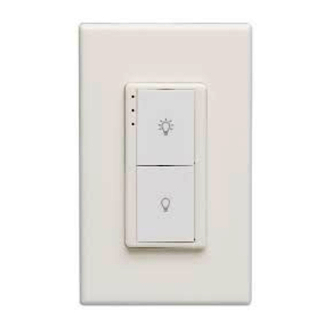
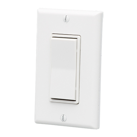
The wireless switches communicate with controllers to acvate the controllers
internal relay. In most applicaons, the controller’s relay is connected to a
lighng load or circuit and the wireless switch funcons as a basic light switch.
The switches requires no wiring connecons and use no baeries. The kinec
energy of a nger press with the ON or OFF side of the switch generates enough
energy to transmit the switch event.
Some models have 4 buons or dual paddles, these operate idencally to the
single paddle switches. With dual switch models, each switch is separate from
the other and can be assigned to the same controller or a dierent controller.
Careful consideraon should be made for locang the controllers and switches
based on the construcon materials in the space and possibility of tenant’s
furniture disrupng the transmissions. The switch should be installed in the
space where the controller device is controlling the light xtures or circuits
however the signal will travel through material barriers, refer to the range
planning secon for more informaon.
wall, desk, cubicle wall,
etc. with double sided tape (supplied with ETRS models only) or Velcro™ (not
supplied). The side of the switch should be mounted on the top; The
indicates (on the front of the Wave and the back of the Decora switches).
The indicates . The Resonate Handheld switches have a depression on
the side of the paddle.
have four (4) mounng holes in the rear mounng
plate to aach the switch to a wall surface with screws and wall anchors (not
supplied). Install a decorator style faceplate (Leviton 80401 or equivalent-not
supplied) over the switch. Test operaon of the switch. The paddle should return
to a neutral posion aer release. An audible click is expected.
come supplied with double sided tape, you can also remove
the front cover of the switch and use the screw guides on the back plate of the
switch to mount with screws and wall anchors (not supplied)
have round removable covers on the back (twist o, using
small holes for leverage). There are keyholes behind the covers. Use with pre-
installed screws (not supplied) - measure 6 cm center to center when placing
screws.
is acvated with an 85.60 x 53.98 mm (3.37 x 2.125”) card
as specied by ISO/IEC7810 - ID-1 (thickness of 0.76 mm (0.03”).
For wall mounng, the keycard switch faceplate must be removed before
mounng with screws. For proper operaon, the provided rear mounng plate
must be used when mounng.
1. Remove the faceplate screws and faceplate assembly (includes front cover
and insert with key depression tag).
2. There are four (4) mounng holes in the rear mounng plate to aach the
switch to a wall surface with screws and wall anchors (not supplied).


