echoflex PTM365nx User manual

PTM-ETR
Installaon Guide
This install guide covers all Echoex Soluons switches, models and descripons below.
The character n in the model number is replaced with U for 902MHz, Y for 868MHz and
J for 928 MHz radios. The character x is replaced with a color indicator ( W = white, G =
gray, B = black, A = light almond, V = ivory).
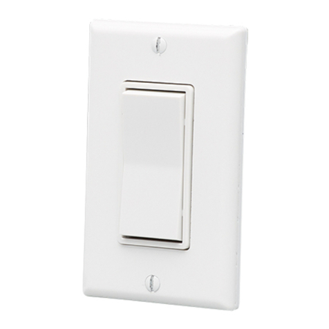
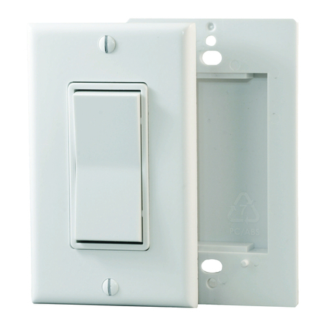
PTM365nx- Single decorator style barrier switch
PTM365Dnx - Dual decorator style barrier switch
Available in white and gray. Includes switch, face plate, barrier plate and mounng
screws
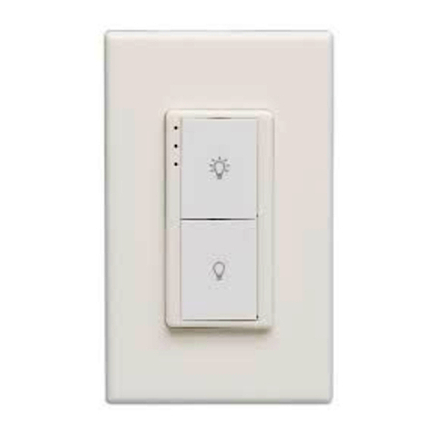
PTM265nx- Single paddle decorator style wireless surface mount switch
PTM265Dnx - Dual paddle decorator style wireless surface mount switch
Available in black, light almond and ivory. Includes switch and surface mount plate
nx - Single paddle wave style wireless surface mount switch
nx - Dual paddle wave style wireless surface mount switch
Available in white and black. Includes switch and clear double sided tape
nW - Single paddle hand-held wireless switch, white
ETRH2nW - Dual paddle hand-held wireless switch, white
PTM265KCAnW - Keycard acvated wireless surface mount switch, white
The switches communicate wirelessly with Echoex lighng controllers to control the
internal relay and/or output dimming level. Common switch applicaons include basic
on/o lighng or dimming.
The energy of a nger press upon the ON or OFF side of the switch paddle generates
sucient energy to transmit the switch event. Addionally, as there is no baery to
replace, there is also no maintenance.
Some models have dual paddles which operate idencally to the single paddle switches.
Each paddle can be linked to dierent controllers for mulple circuit control from one
wall staon.

2
Careful consideraon should be made when locang the controllers and switches based
on the construcon materials in the space and possibility of tenant’s furniture disrupng
the transmissions. The switch should be installed in the space where the controller
device is controlling the light xtures or circuits.
The surface mount and Wave switch models can be mounted on any surface; wall, desk,
cubicle wall, using double sided tape or Velcro™ (not supplied). The switches also have
screw holes for more secure mounng requirements.
The ON side of the paddle should be oriented at the top of the mounted switch. The
decorator style switches have an arrow poinng towards plus have an “I” indicang
and “O” indicang on the back of the switch (Wave switches also have this on the
front). The hand-held switches have a depression indicang the side of the paddle.
These models include a barrier plate and are designed to be mounted to electrical wall
boxes.
1. Install the barrier plate and the switch on the box through the two oval holes using
the provided #6-32 screws.
2. Install the provided decorator style face plate over the switch.
3. Test the operaon of the switch. The paddle should return to the neutral posion
aer release. An audible click is expected.
#6-32
3060167
Conforms to UL Std. UL514D
Cert. to CSA Std. C22.2 No. 42.1

3
1. Mount the surface mounng plate to the wall surface with screws and wall anchors
(not supplied).
2. Mount the switch to the plate with the two short #6-32 screws provided.
3. Install a decorator style faceplate (Leviton 80401 or equivalent, not supplied) over
the switch.
4. Test operaon of the switch. The paddle should return to a neutral posion aer
release. An audible click is expected.
These models come supplied with clear double sided tape, you can also remove the front
cover of the switch and use the screw guides on the back plate of the switch to mount
with screws and wall anchors (not supplied).
These models have round removable covers on the back (twist o, using small holes
for leverage). There are keyholes behind the covers. Use with pre-installed screws (not
supplied) - measure 6 cm center to center when placing screws.
The keycard switchis acvated with an 85.60 x 53.98 mm (3.37 x 2.125”) card as specied
by ISO/IEC7810 - ID-1 (thickness of 0.76 mm (0.03”).
For wall mounng, the keycard switch faceplate must be removed before mounng.
For proper operaon, the provided rear surface mounng plate must be used when
mounng.
1. Remove the faceplate screws and faceplate assembly (includes front cover and
insert with key depression tag).
2. There are four mounng holes in the rear mounng plate to aach the switch to a
wall surface with screws and wall anchors (not supplied). Note: the keycard switch
can be oponally wall box mounted with the barrier paron accessory (sold
separately).
3. Reinstall the faceplate assembly. DO NOT OVER TIGHTEN THE SCREWS.
4. Test operaon of the switch by inserng a card and extracng. There should be an
audible click with each inseron and extracon.
The linking process requires the controller or receiver to be mounted, powered and
within range of the switch to be linked. Each receiver can support up to 20-30 switches,
depending on receiver model.
1. Acvate LEARN or LINK mode at the receiver, if necessary refer to the
manufacturers documentaon.
2. Wall and handheld switches: triple click quickly. For keycard switches: insert a
room card into the switch three (3) mes quickly.
3. Deacvate LEARN mode at the receiver. Test operaon of the switch by switching
and .

4
#1, 38924 Queens Way | Squamish | BC | Canada | V8B 0K8
Toll Free: 888-324-6359 | Phone: (778) 733-0111 | Fax: (604) 815-0078
Email: info@echoexsoluons.com | www.echoexsoluons.com
Single or Dual Paddle Switches EEP: F6-02-02
Keycard Switch EEP:F6-04-01
PTM365BP1* - Single gang barrier plate for decorator style switches
PTM365BP2* - Dualgang barrier plate for decorator style switches
* Available in White or Gray
PTM3651GF* - 1 gang ush mounng plate kit (screws included)
* Available in White or Gray
PTM2651GF* - 1 gang ush mounng plate for decorator style switches
PTM2652GF* - 2 gang ush mounng plate for decorator style switches
PTM2653GF* - 3 gang ush mounng plate for decorator style switches
* Available in Black, Light Almond or Ivory (V)
SC01- Anmicrobial Silicone Sleeve, for use with decorator style switch only
The enclosed device complies with Part 15 of the FCC Rules.
Operaon is subject to the following two condions:
(I.) this device may not cause harmful interference and
(ii.) this device must accept any interference received, including interference that may cause
undesired operaon.
Devices equipped with 902 MHz radio:
Contains FCC ID: SZV-PTM210U
Contains IC: 5713A-PTM210U
Devices equipped with 868 MHz radio:
Contains FCC ID: SZV-PTM210
Contains IC: 5713A-PTM210
Devices equipped with 928 MHz radio:
Contain PTM 210J which complies with the Japanese radio law and is
cered according to ARIB STD-T108
UL Standard 514D
CSA Standard C22.2 # 42-1-13
For more informaon on Echoex Soluons, scan the QR code:
Copyright 2013-2018 Echoex Soluons, Inc. | Specicaons subject to change without noce.
Document #8DC-5303 | Revision 3.0 | 8188M21-5303-1 | Rev F
3060167
This manual suits for next models
8
Table of contents
Other echoflex Switch manuals
Popular Switch manuals by other brands
Leviton
Leviton 83A00-1 installation manual

Sunshine Tech
Sunshine Tech Smart Touch Light Switch user manual
Extron electronics
Extron electronics DTP2 T 212 user guide
Crestron
Crestron DigitalMedia DM-MD8X8-CPU3 product manual
Cable Electronics
Cable Electronics HS103 operating instructions

Lanpro
Lanpro LP-SGW2400 user manual

KTI
KTI KS-316F installation guide
Dantel
Dantel 46034 Installation & operation manual
PCB Piezotronics
PCB Piezotronics IMI SENSORS 685B1001A21 Installation and operating manual

Rutenbeck
Rutenbeck TCR IP 4 operating instructions

Cisco
Cisco MDS 9120 - Fabric Switch manual
Panasonic
Panasonic PN28080K-TH installation guide
