Ecodan EHPT18X-UKHLDWB Guide

UNVENTED MAINS PRESSURE WATER HEATER
WITH FTC6 CONTROL SYSTEM. FOR USE WITH
ECODAN PUZ-(H)WM AIR SOURCE HEAT PUMP
RANGE.
IMPORTANT: PLEASE READ AND UNDERSTAND THESE INSTRUCTIONS
BEFORE COMMENCING INSTALLATION , OPERATING THE UNIT OR
PERFORMING ANY MAINTENANCE.
PLEASE LEAVE THIS MANUAL WITH THE CUSTOMER FOR FUTURE REFERENCE.
Installation, Operation, Service & Parts Manual
Renewable Heating Technology
July 2023
Doc. No. 685702
EDITION-1
EHPT18X-UKHLDWB
EHPT21X-UKHLDWB
EHPT21X-UKHDWB
EHPT25X-UKHDWB
EHPT30X-UKHDWB

2
Contents
Abbreviations and Glossary 2
Safety Precautions 3
Introduction 5
6
Product Diagrams 7
Fiche Performance Data 7
Preparing to Install the Cylinder 8
Installation Instructions 9
Wiring Diagram 15
Electrical Work 16
System Set Up 19
Operator and owner info 30
Commissioning 37
Servicing 38
Annual Maintenance Log Book 39
Servicing 40
Troubleshooting 59
Test Plot Diagram 72
Disassembly / Decommissioning Procedure 73
Service & Maintenance 76
Parts List 79
No. Abbreviations/Word Description
1 Compensation curve mode Space heating incorporating outdoor ambient temperature compensation
2 COP
3 Cylinder unit Indoor unvented DHW tank and component plumbing parts
4 DHW mode Domestic hot water heating mode for showers, sinks etc.
5 Flow temperature Temperature at which water is delivered to the primary circuit
6 Freeze stat. function Heating control routine to prevent water pipes freezing
7 FTC Flow temperature controller, the circuit board in charge of controlling the system
8 Heating mode
9 Legionella Bacteria potentially found in plumbing, showers and water tanks that may cause Legionnaires' disease
10 LP mode Legionella prevention mode – a function on systems with water tanks to prevent the growth of Legionella bacteria
11 Packaged model Plate heat exchanger (Refrigerant - Water) in the outdoor heat pump unit
12 PRV Pressure relief valve
13 Return temperature Temperature at which water is delivered from the primary circuit
14 Split model Plate heat exchanger (Refrigerant - Water) in the indoor unit
15 TRV Thermostatic radiator valve – a valve on the entrance or exit of the radiator panel to control the heat output
16 Cooling mode
Abbreviations and Glossary
3
Safety Precaution
WARNING:
Precautions that must be observed to prevent injuries or death. CAUTION:
Precautions that must be observed to prevent damage to unit.
Please read the following safety precautions carefully.
• Be sure to perform periodical maintenance.
• Be sure to follow your local regulations.
• Be sure to follow the instructions provided in this manual.
MEANINGS OF SYMBOLS DISPLAYED ON THE UNIT
WARNING
This mark is for R32 refrigerant only. Refrigerant type is written on nameplate of outdoor unit.
Read the OPERATION MANUAL carefully before operation.
Service personnel are required to carefully read the OPERATION MANUAL and INSTALLATION MANUAL before operation.
Further information is available in the OPERATION MANUAL, INSTALLATION MANUAL, and the like.
WARNING
Mechanical
The cylinder unit and outdoor unit must not be installed, disassembled, relocated, altered or repaired by the user. Ask an authorised installer or technician. If the unit is installed improperly
Do not position furniture or electrical appliances below the outdoor unit or cylinder unit.
The discharge pipework from the emergency devices of the cylinder unit should be installed according to local law.
Electrical
The units must be powered by a dedicated power supply and the correct voltage and circuit breakers must be used.
Wiring should be in accordance with national wiring regulations. Connections must be made securely and without tension on the terminals.
Earth unit correctly.
Discharge the condenser before the work involving the electric parts.
General
Keep children and pets away from both the cylinder unit and outdoor units.
Do not use the hot water produced by the heat pump directly for drinking or cooking. This could cause illness to the user.
Do not stand on the units.
Do not touch switches with wet hands.
Do not place any heavy items on top of the cylinder unit.
allow air to remain in the lines. If air is mixed with refrigerant, then it can be the cause of abnormal high pressure in the refrigerant line, and may result in an explosion and other hazards.
impediment to securing product safety.
Do not use means to accelerate the defrosting process or to clean, other than those recommended by the manufacturer.
Do not pierce or burn.
Be aware that refrigerants may not contain an odour.
Pipework shall be protected from physical damage.
The installation of pipework shall be kept to a minimum.
Compliance with national gas regulations shall be observed.
Keep any required ventilation openings clear of obstruction.
Do not use low temperature solder alloy in the case of brazing the refrigerant pipes.
In the case of a refrigeration leak, stop the operation of the unit, thoroughly ventilate the room and contact the installer.
4
CAUTION
Use clean water that meets local quality standards on the primary circuit.
The cylinder unit should be located inside to minimise heat loss.
Water pipe-runs on the primary circuit between outdoor and indoor unit should be kept to a minimum to reduce heat loss.
Ensure condensate from outdoor unit is piped away from the base to avoid puddles of water.
Remove as much air as possible from the primary and DHW circuits.
Be sure to wrap insulation around the piping. Direct contact with the bare piping may result in burns or frostbite.
Never put batteries in your mouth for any reason to avoid accidental ingestion.
Battery ingestion may cause choking and/or poisoning.
Install the unit on a rigid structure to prevent excessive sound or vibration during operation.
Do not transport the cylinder unit with water inside the DHW tank. This could cause damage to the unit.
Preventative measures should be taken against water hammer, such as installing a Water HammerArrestor on the primary water circuit, as directed by the
manufacturer.
As for the handling of refrigerant, refer to the outdoor unit installation manual.
[1] Cautions for service
(1) Perform service after recovering the refrigerant left in unit completely.
(2) Do not release refrigerant in the air.
(4) If moisture or foreign matter might have entered the refrigerant piping during service, ensure to remove them.
[2] Additional refrigerant charge
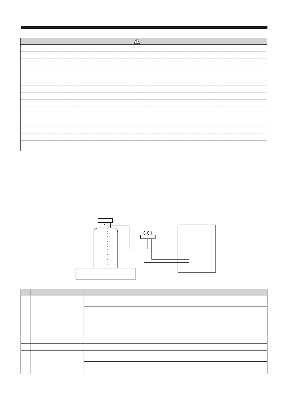
When charging directly from refrigerant cylinder
(1) Check that cylinder for R410Aor R32 on the market is syphon type.
(2) Charging should be performed with the cylinder of syphon stood vertically. (Refrigerant is charged from liquid phase.)
[3] Service tools
Use the service tools below as exclusive tools for R410A or R32 refrigerant.
No. Tool name Specications
1Gauge manifold R410A or R32
Use high-tension side pressure of 5.3 MPa·G or over.
2Charge hose R410A or R32
Use pressure performance of 5.09 MPa·G or over.
3Electronic weighing scale —
4Gas leak detector Use the detector for R134a, R407C, R410A or R32.
5 Attach on vacuum pump.
6Refrigerant charge base —
7Refrigerant cylinder R410A or R32
Top of cylinder (Pink)
Cylinder with syphon
8 Refrigerant recovery equipment —
Electronic weighing scale
Unit
5
CAUTION
• Do not use sharp objects to press the buttons of the main remote controller as this will cause damage to the buttons.
Disposal of the Unit
Note: This symbol mark is for EU countries only. This
symbol mark is according to the directive 2012/19/EU
Article 14 Information for users and Annex IX, and/or
to the directive 2006/66/EC Article 20 Information for
end-users and Annex II.
This symbol indicates that this product must not be disposed of with
general household waste, to prevent damage to the environment and
risk to personal health.
Instead, it is your responsibility to ensure the product is
decommissioned and disposed of safely by isolating the electricity
supply to the immersion heater and heat pump, before draining
must then dispose of the cylinder by handing it over to a designated
recycling centre for domestic waste electrical equipment. Contact your
or to arrange a collection.
Introduction
hot water expansion vessel, cold water combination valve, tundish, Wi-Fi adapter harness and Mitsubishi main remote control.
IMPORTANT NOTE TO THE INSTALLER
You must ensure the installation complies with the current Building Regulations and/or Technical Standards Documents for England,
Scotland or Wales.
IMPORTANT NOTE
All goods are sold subject to Mitsubishi Electric’s Terms and Conditions of Sale.
Important Note:
Included with the Ecodan product is information about how to register the Mitsubishi Electric user guarantee. Please direct the end user
and any cylinder or interfacing equipment purchased from Mitsubishi Electric by you as installer.
The guarantee applies where the installation address is in England, Scotland or Wales only and for domestic use. This registration
should be completed only by the end user/system owner so please ensure that the information about how to register the Mitsubishi
Electric user guarantee reaches them. There are various options to register the guarantee and details can be found online at
https://les.mitsubishielectric.co.uk. The registration is logged by our warranty department. In the unlikely event of failure of the Ecodan
heat pump or any such cylinder or interfacing equipment purchased from Mitsubishi Electric, registration of the guarantee ensures
contact details on back page).
Please Note:
If you do not register the Mitsubishi Electric user guarantee then the product will only be guaranteed to the user by Mitsubishi Electric
consumer rights under applicable national legislation.

6
Specication Details
The unvented cylinders are made from Duplex stainless steel
for corrosion resistance, are encased in a strong rust-proofed
steel case and are highly insulated with environmentally-
friendly foam. Further details are below.
Materials
• Inner shell – Duplex stainless steel
• Coil – 22mm diameter stainless steel
28mm diameter stainless steel
• Bosses – stainless steel
• Polyurethane CFC- and HCFC-free foam insulation. This
insulation has an Ozone Depletion Potential of Zero and
a Global Warming Potential of 1
• Anode – none required
All cylinders are welded using a controlled oxygen purged
process to maximise the corrosion resistant qualities of the
high-grade Duplex stainless steel. Every cylinder is checked
using 15 bar pressure testing.
Immersion heater
• 1 ¾” BSP parallel threaded head
• Titanium long life low noise element
• Brazed construction
• Safety cut-out
• Element rating 3kW at 230-240 Volt A/C
Flow rates
The graph below illustrates the speed at which hot water can
be distributed reliably throughout the home.
Coil Presure Drop
Slimline Cylinders
Standard Cylinders
Pressure specications - The Unvented Cylinder
Maximum Inlet Water Pressure 12.0 bar
Operating Pressure/Maximum Design Pressure 3.0 bar
Expansion Valve Opening Pressure 6.0 bar
Expansion Vessel Charge Pressure 3.0 bar
Maximum Operating Pressure 3.0 bar
Opening Pressure of T & P Valve 7.0 bar
Opening Temperature of T & P Valve
Maximum Coil Pressure 3.5 bar
Immersion Element specications
Element Rating 3kW 230-240 Volt
Thread Type 1¾” BSP
Fuse Requirement (Via FTC6) 16A
Control Thermostat (Via FTC6)
High Limit Thermostat Set Point
0
0.1
0.2
0.3
0.4
0.5
0.6
0
5
10
15
20
25
30
Pressure drop (Bar)
Flow rate (LPM)
0
0.05
0.1
0.15
0.2
0.25
0.3
0
5
10
15
20
25
30
Flow rate (LPM)
Pressure drop (Bar)
0
10
20
30
40
50
60
70
80
90
2 2.5 3 3.5
Water Pressure (Bar)
Flow Rate (LPM)
4 4.5 5
7
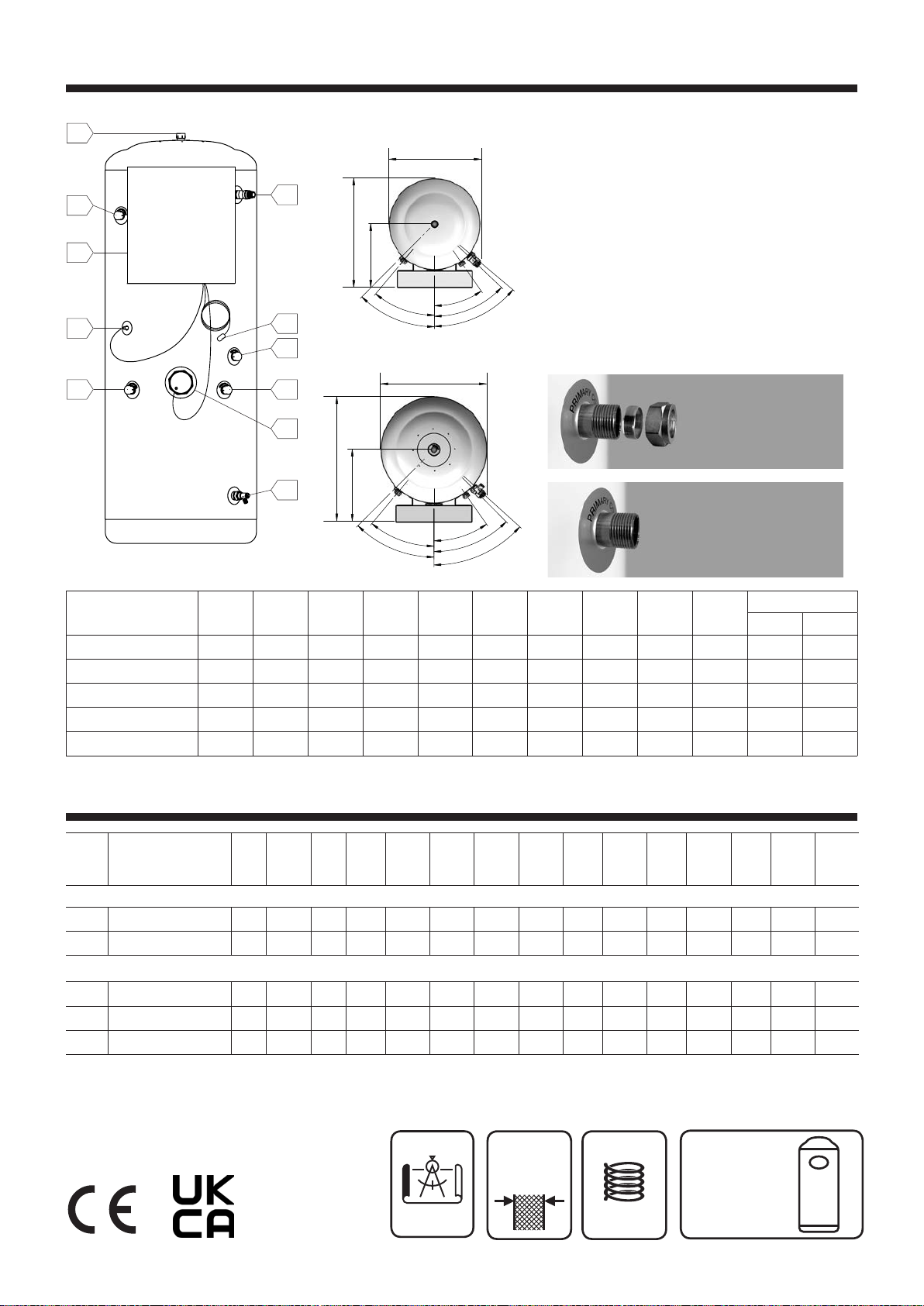
Product Diagrams
A
J
H
C
G
I
B
F
DD
E
Slimline
Standard
Connections
A Cold feed - 22mm / ¾" BSP
B Hot water outlet - 22mm / ¾" BSP
C 3kW 14" Immersion heater - 1¾" BSP
D Heat pump coil connections - 22mm / ¾" BSP
- ½”NPT x 15mm
F Secondary return - 22mm / ¾" BSP
(Excluding EHPT18X-UKHLDWB)
G Dry stat pocket - 10mm
H Drain cock
I FTC6 Controller
J Wi-Fi Adaptor (installer to locate and mount)
Product
Codes
Total
Height
(mm)
Diameter
(mm) A
(mm) B
(mm) C
(mm) D
(mm) E
(mm) F
(mm) G
(mm) HFTC6 Controller
Bottom Top
EHPT18X-UKHLDWB 1712 475 726 1712 756 668 1479 N/A 864 158 1156 1578
EHPT21X- UKHLDWB 2025 475 726 2025 769 668 1795 1615 1020 158 1156 1578
EHPT21X-UKHDWB 1495 550 680 1495 584 558 1273 1150 768 173 1018 1440
EHPT25X-UKHDWB 1745 550 680 1745 654 558 1523 1400 893 173 1156 1578
EHPT30X-UKHDWB 2058 550 680 2058 654 558 1836 1600 1050 173 1156 1578
376
40°
45°
35°
45°
48°
40°
46.5°
35°
50°
45°
332
651
550
570
475
376
40°
45°
35°
45°
48°
40°
46.5°
35°
50°
45°
332
651
550
570
475
¾" BSP parallel male thread
connections without
nut & olive
22mm compression
connections when using
the nut & olive
Fiche - Technical Performance Data
Nominal
Capacity
(Litre)
Product
Codes Energy
Rating
Standing
Loss
(W)
Total
Height
(mm)
Diameter
(mm)
Weight
Empty
(kg)
Weight
Full
(kg)
Actual
Cylinder
Capacity
(Litre)
Expansion
Vessel
(Litre)
Heat-up
Time
(Min.)
Heat
Loss
(kW/24Hr)
Coil
Primary
Flow
(L.P.M.)
Coil
Pressure
Drop
(Bar)
Coil
Surface
Area
(m2)
Coil
Capacity
(Litre)
Coil
(kW
Rating)
Heat pump slimline unvented hot water cylinders
180 EHPT18X-UKHLDWB C 72 1712 475 45 218 173
19
20 1.72 15 0.14 1.7 8.0 32
210 EHPT21X-UKHLDWB C 87 2025 475 51 259 208
19
24 2.08 15 0.14 1.7 8.0 32
Heat pump unvented hot water cylinders
210 EHPT21X-UKHDWB C 75 1495 550 48 242 195
19
24 1.79 15 0.08 2.3 14.3 32
250 EHPT25X-UKHDWB C 84 1745 550 53 288 235
24
29 2.02 15 0.08 2.3 14.3 32
300 EHPT30X-UKHDWB C 93 2058 550 60 345 285
24
34 2.24 15 0.08 2.3 14.3 32
3 Bar
Max design
pressure (DHW)
Insulation
Thickness
50mm
3.5 Bar
Max primary
coil pressure
Recommended
Minimum Input
25 L.P.M.
@
1.5 Bar
Tested in accordance with BS EN 12897:2016+A1:2020
(closed) storage water heaters.

8
Preparing To Install the Cylinder
Storage prior to installation
The unvented cylinder should be stored in its original
packaging in an upright position in a dry, frost-free
environment.
Handling product
The unvented cylinder should be carried upright where
possible. Assessments of risks for carrying the unit should
be conducted. Use more than one person for carrying where
components such as the T&P valve or immersion heater.
Always follow latest guidelines for lifting techniques to avoid
injury or damage to the product.
Water supply
The unvented cylinder operates at 3 bar (controlled by the
cold water combination valve) and is capable of delivering
over 50 litres per minute. The cold water combination valve
available, however the performance of any unvented system
is only as good as the mains water supply. The maximum
possible water demand should be assessed, taking into
consideration that both hot and cold services are supplied
simultaneously from the mains.
The water supply should be checked to ensure it can
meet these requirements. If necessary, consult the local
availability.
If measuring the water pressure, note that a high static (no
In a domestic installation 1.5 bar and 25 L/min. should be
regarded as the minimum. The maximum mains pressure that
the cold water combination valve can accept is 12 bar.
Consideration should be given to upgrading existing
½" (15mm) cold mains pipework to a larger size if the
achieved.
Note: the system must be fed from domestic mains water
supply compliant with Water Regulations 2000 and the use
of well water or a private borehole will void the cylinder’s
Warranty.
Siting the unit
The unvented cylinder can supply outlets above it or at
some distance from it. Site the unit to minimise “dead
leg” distances, especially to the point of most frequent
use. Outlets above the unvented cylinder will reduce the
outlet pressure available by 0.1 bar for every 1m of height
The unvented cylinder must be installed indoors in a frost-free
environment and all exposed pipework should be insulated.
The units must be installed in the correct orientation, i.e.
the cylinder when full. See the illustration and table for the
minimum recommended cupboard size; take care to ensure
the discharge pipe(s) from its safety valves can be correctly
installed - see discharge arrangement on page 13 & 14.
Model Cylinder
ø
mm
Airing Cupboard Size
Width
mm Depth
mm Height
mm
EHPT18X-UKHLDWB 475 675 675 1832
EHPT21X-UKHLDWB 475 675 675 2145
EHPT21X-UKHDWB 550 750 750 1615
EHPT25X-UKHDWB 550 750 750 1865
EHPT30X-UKHDWB 550 750 750 2178
50mm
410mm
100mm 100mm
120mm
H
Ceiling or similar
flat surface capable of supporting the weight when full
50mm
410mm
100mm 100mm
120mm
H
Ceiling or similar
flat surface capable of supporting the weight when full

9
Preparing To Install the Cylinder
Access
Consideration should be given to the position of discharge
pipes (tundish) drain valves. Avoid positioning these too close
space so that the cylinder can be inspected, maintained and
serviced in the future.
The immersion heaters are 410mm long and care should
be taken to ensure that they can be withdrawn, enabling the
immersion heater to be replaced at the end of its working life
and providing inspection access to the interior of the cylinder
in servicing if required. The discharge pipework from the
safety valves should fall continuously and terminate safely.
AAV’s
Additional automatic air vents (AAV) (not supplied) may be
required at high points in the primary system where pipework
system (primary circuit), release all trapped air using air vents
during and following heating period and top up with water as
necessary. After removing the air, automatic air vent(s) MUST
be closed.
Flushing the heating system
(Retrot installations)
Part L of the 2022 Building Regulations require that all central
heating systems are cleaned and dosed with protective
as the heat pump, to protect the equipment from damage.
Ecodan heat pumps also require anti-freeze protection.
Failure to do so will put the product Warranty at risk.
Turn to test
Cold water combination valve Cold
Mains In
Expansion Relief
to Tundish
Balanced Cold
Connection
Outlet to Cylinder
Cold mains pipework
Option 1: Run the cold mains through the building to the place
where the unvented cylinder is to be installed.
Option 2. Where local Building Regulations do not permit
the cylinder to be connected directly to mains supply, run the
cold feed from a cold feed break tank using a suitable pump
to boost pressure. The pump MUST be used in conjunction
with a sensor in the feed tank to ensure tank does not drain
empty and pull air. Take care to prevent heat pick-up by not
running the cold pipe near hot water or heating pipework. This
(not supplied). We recommend using a full bore quarter turn
ball valve; alternatively a stopcock can be used, however this
similar service valve.
Make the connection to the cold feed of the cylinder with
the cold water combination valve positioned above the
Temperature & Pressure Relief Valve (TPRV) mounted on
the side of the cylinder. This ensures that the cylinder does
not have to be drained down in order to service the cold
water combination valve. Ensure that the arrow points in the
Select a suitable position for the potable water expansion
vessel. Mount it to the wall using the bracket attached to the
weight (and with appropriate consideration to wall material).
Connect the expansion vessel to the cold feed pipework
between the cold water combination valve and the cold inlet
on the cylinder. Ensure that the top of the vessel is accessible
for servicing.
Cylinder connections
The cylinder should be plumbed in using BS EN1057-R250
copper tube. Cut the tube square using a rotary tube cutter
and ensure no sharp edges or burrs protrude. Slide both
gland nut and olive onto the tube and push tube fully home
into the connection, ensuring the tube end fully bottoms on
the connection recess. Smear the outer wall of the olive with
plumbing paste and tighten the gland nut in the prescribed
manner.
Alternatively, if you are using imperial pipework, you may
the BSP thread on the cylinder boss.
completely watertight, including bosses and any pre-plumbed
components.
the expansion relief valve and the storage cylinder. The relief
valve connections should not be used for any other purpose.
Installation Instructions - Unvented Cylinders

10
Installation Instructions - Unvented Cylinders
Balanced connections
A balanced hot and cold supply is necessary to stop one
from overpressurisation of the other. This can be achieved
by feeding all cold outlets from the 22mm balanced cold
connection featured on the cold water combination valve. If
you are not using this balanced cold connection and using an
cold water combination valve’s balanced cold connection.
Where there are showers, bidets or monobloc mixing taps
in the installation, these need to be installed to comply with
the Water Supply (Water Fittings) Regulations 1999. If these
devices have unbalanced supplies, there must be single
check valves installed at both inlets.
Hot water pipework
Run
suit the type of tap for example. You should aim to keep the run
length of any hot water pipework from the cylinder to outlet to a
practical minimum so the time taken for the hot water to reach
the outlet is as quick as possible. Then connect the hot water
the diagram on page 7).
Connections - heat pump coil
The cylinders are suitable for use with Ecodan PUZ-(H)WM
Air Source heat pumps; see compatibility table bellow.
be pumped. Gravity circulation is not suitable.
The heat pump cannot be vented through the cylinder.
Solid fuel boilers or any other boiler in which the energy input
and appropriate safety measures are installed, should NOT
be used. The primary circuit must be a sealed system type,
sized expansion vessel for the size of the heating system.
Ecodan R32 heat pumps include an integral 3 bar PRV. No
additional PRV’s should be added to the circuit.
heating of the cylinder.
Water Quality and System Preparation
General
The water in both primary and sanitary circuit should be clean
and with pH value of 6.5-8.0.
The following are the maximum values:
• Calcium: 100 mg/L, Ca hardness: 250 mg/L, Chloride:
100 mg/L, Copper: 0.3 mg/L
• Other constituents should be to European Directive
98/83 EC standards.
• In known hard water areas, to prevent/minimise scaling, it
Anti-freeze
Anti-freeze solutions MUST use propylene glycol with a
toxicity rating of Class 1 as listed in Clinical Toxicology of
Commercial Products, 5th Edition.
Notes:
1) Ethylene glycol is toxic and MUST NOT be used in the
primary water circuit in case of any cross-contamination of
the potable circuit.
2) For 2-zone valve ON/OFF control, propylene glycol MUST
be used.
New and existing installations (primary water circuit)
Before connecting outdoor unit, thoroughly cleanse pipework
of building debris, solder etc. using a suitable chemical
cleansing agent.
Flush the system to remove chemical cleanser.
Add a combined inhibitor and anti-freeze solution to prevent
damage to the pipework and system components.
Corrosion inhibitor should always be used.
When using chemical cleansers and inhibitors always follow
the manufacturer’s instructions and ensure the product is
appropriate for the materials used in the water circuit.
Slimline Standard
EHPT18X-UKHLDWB EHPT21X-UKHLDWB EHPT21X-UKHDWB EHPT25X-UKHDWB EHPT30X-UKHDWB
PUZ-WM50 VHA(-BS) •••
PUZ-WM60 VAA(-BS) •••••
PUZ-WM85 (V-Y)AA(-BS) •••••
PUZ-WM112 (V-Y)AA(-BS) •••••
PUZ-HWM140(V-Y)HA •••••
Heat Pump to Cylinder Compatibility
11
Installation Instructions - Unvented Cylinders
Minimum required water volume and required
primary ow rates
Outdoor heat pump unit Min. water
volume Required
ow rate
PUZ-WM50VHA 7L 14.3L/min
PUZ-WM60VAA 9L 17.2L/min
PUZ-WM85(V-Y)AA 12L 24.4L/min
PUZ-WM112(V-Y)AA 16L 32.1L/min
PUZ-HWM140(V-Y)HA 20L 40.1L/min
If the interlock operation of primary and secondary pump is
not available, ensure required additional water in only primary
circuit. If the interlock operation of primary and secondary
pump is available, ensure total water amount in primary and
secondary circuit. In the case of shortage of required water
Secondary circulation connection
The cylinders can be used with secondary circulation if
required. Use an appropriate WRAS approved bronze
or stainless steel circulator in conjunction with a WRAS
secondary circulation systems it may be necessary to
incorporate an extra expansion vessel into the circuit to
accommodate the increased system water volume.
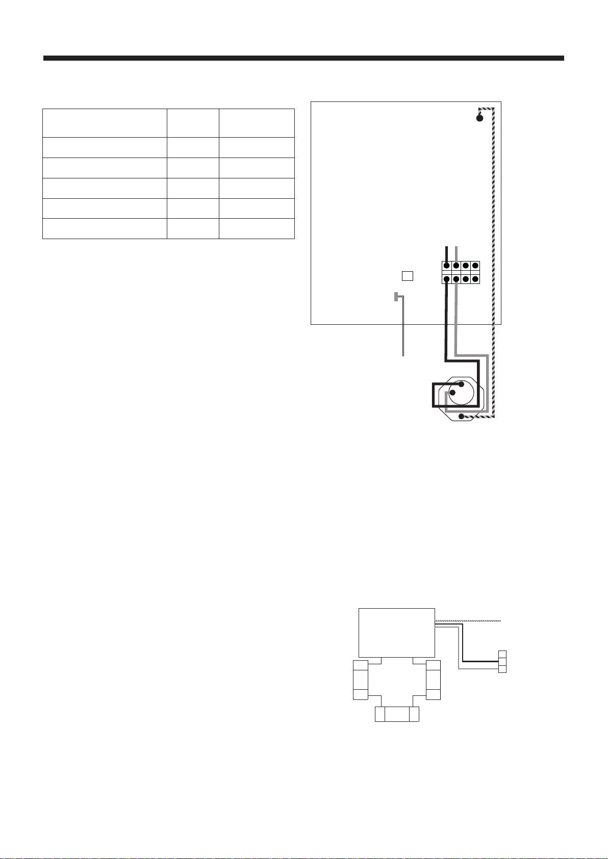
Important: Immersion to be wired via FTC6. For full
to diagram opertit.
Electrical supply to the immersion heater
The unvented cylinder requires 230-240 Volt electrical
supply for the immersion element. The electrical supply to
the immersion heater must be fused at 16A via a double
pole isolating switch that meets the current BS Standards. A
breaker with at least 3.0mm contact separation in each pole
shall be provided. Use an earth leakage breaker (NV). The
breaker shall be provided to ensure the disconnection of all
active phase conductors of the supply. The cable must be
at least 2.5mm2
complying to the current BS Standards.
Electrical supply to the 3-way diverter valve
The 3-way diverter valve uses 230-240 Volt electrical supply.
connecting via FTC box.
Do not grip the valve head while tightening or adjusting
plumbing connections. Flow from the heat pump must be
MUST
NOT be mounted below horizontal level of pipework.
Immersion Heater
To
Thermostat
SD
Live
(Brown) Neutral
(Blue) Earth (Yellow/Green)
Immersion Heater Wiring
2/T1
1/L1 3/L2
4/T2 5/L3
5/T3 A1
A2
IHC
CNW5
CN108
A
B
4
5
6
Live (Brown)
Neutral (Blue)
Earth (Yellow/Green)
A
AB
B
To Heating
To Hot Water
OUT 4 TBO.2 4-6
Flow from
Heat Pump
3-way Diverter valve
Immersion Heater Wiring

12
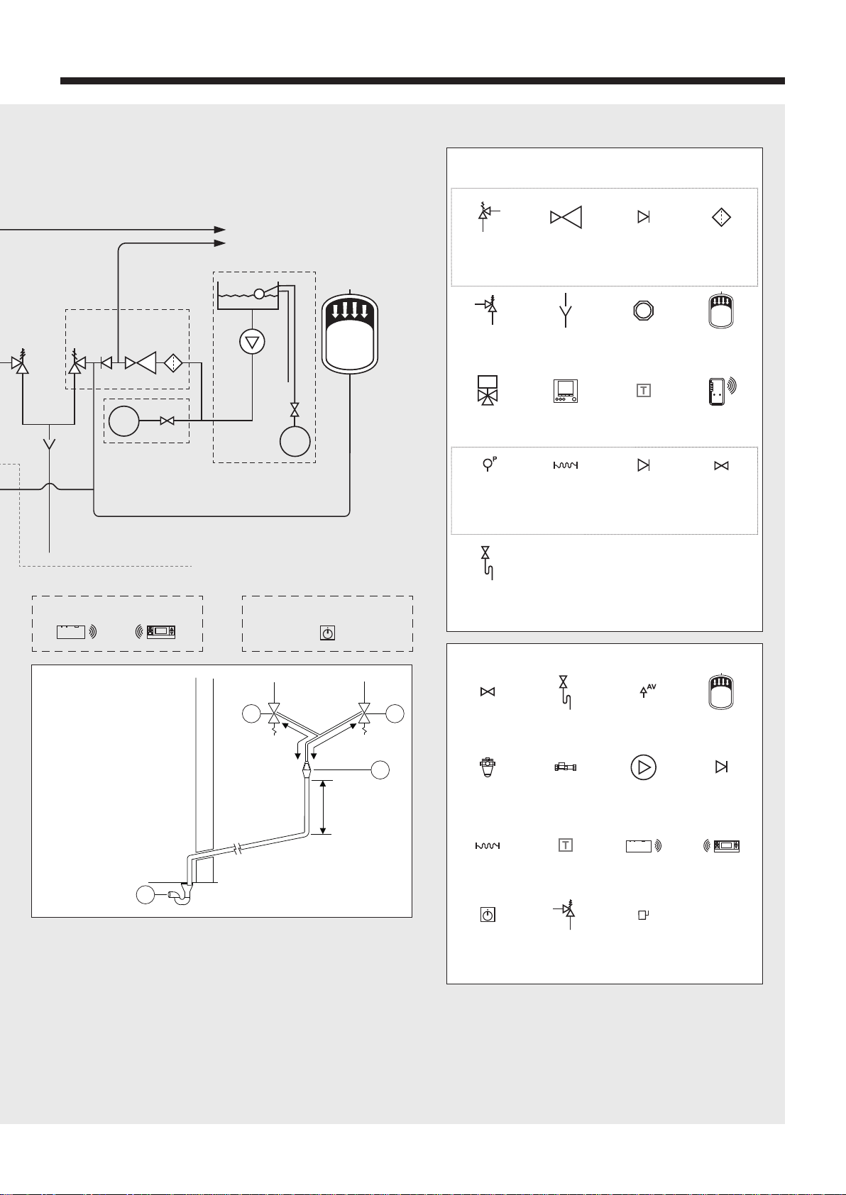
Installation Instructions - Unvented Cylinders (cont.)
T
System Schematic
DRAIN
DRAIN
COLD
MAIN
BALANCED
COLD
To cold water outlets
To hot water outlets
OVERFLOW
Cold water
combination
valve POTABLE
WATER
EXPANSION
VESSEL
COLD
MAIN
COLD
MAIN
Filling Loop, disconnect
when not in use
Opt 2.
Connection via breaker tank
Immersion
230V|SP+N|50Hz
FIC6 Board
230V|SP+N|50Hz
Wi-Fi
Adaptor
Main
Controller
Wireless Transmitter
Rads/FC (Option)
Wireless Receiver
(Option) Room Thermostat / UFH Wiring Centre
(Local Supply)
Zone 1 Heating
Rads/UFH/FC
Zone 1
Call for heating
OR
Flow to heating system
Return from heating system
12V DC
(2 x 0.3mm2)
Refer to detail
on discharge
pipework
System Schematic
Main
Controller
Flushing Bypass
XP+N|50Hz
T
T
AV
HEATING
EXPANSION
VESSEL
SECONDARY RETURN CIRCUIT
(210, 250 & 300L SIZES)
P
FTC6
Opt 1.
Direct mains connection
Detailed Discharge Pipework
Arrangement
1 2
600mm
MAXIMUM
600mm
MAXIMUM
300mm
MINIMUM
3
4
Metal discharge pipe
(D1) from both safety
valves to tundish
Discharge pipe (D2)
from tundish, with
continuous fall.
See Building Regulations
G3 section 3.56,
Table 4 & worked example
Discharge below fixed grating
(Building Regulations G3 section 3.61
gives alternative points of discharge)
1) Expansion relief valve on cold
water combination valve
2) Temperature & pressure relief
valve on cylinder
3) Tundish
4) Drain with fixed grating
13
Installation Instructions - Unvented Cylinders (cont.)
T
System Schematic
DRAIN
DRAIN
COLD
MAIN
BALANCED
COLD
To cold water outlets
To hot water outlets
OVERFLOW
Cold water
combination
valve POTABLE
WATER
EXPANSION
VESSEL
COLD
MAIN
COLD
MAIN
Filling Loop, disconnect
when not in use
Opt 2.
Connection via breaker tank
Immersion
230V|SP+N|50Hz
FIC6 Board
230V|SP+N|50Hz
Wi-Fi
Adaptor
Main
Controller
Wireless Transmitter
Rads/FC (Option)
Wireless Receiver
(Option) Room Thermostat / UFH Wiring Centre
(Local Supply)
Zone 1 Heating
Rads/UFH/FC
Zone 1
Call for heating
OR
Flow to heating system
Return from heating system
12V DC
(2 x 0.3mm2)
Refer to detail
on discharge
pipework
System Schematic
Main
Controller
Flushing Bypass
XP+N|50Hz
T
T
AV
HEATING
EXPANSION
VESSEL
SECONDARY RETURN CIRCUIT
(210, 250 & 300L SIZES)
P
FTC6
Opt 1.
Direct mains connection
Detailed Discharge Pipework
Arrangement
1 2
600mm
MAXIMUM
600mm
MAXIMUM
300mm
MINIMUM
3
4
Metal discharge pipe
(D1) from both safety
valves to tundish
Discharge pipe (D2)
from tundish, with
continuous fall.
See Building Regulations
G3 section 3.56,
Table 4 & worked example
Discharge below fixed grating
(Building Regulations G3 section 3.61
gives alternative points of discharge)
1) Expansion relief valve on cold
water combination valve
2) Temperature & pressure relief
valve on cylinder
3) Tundish
4) Drain with fixed grating
Key:
Items supplied with cylinder
Other items
Pressure
reducing valve
Flexihose
3-way diverter
valve Thermostat
(cylinder)
Drain cock
Flow
sensor
Thermostat
Pressure and
temperature
relief valve
Pressure
relief valve
Pressure
gauge
Pressure and
temperature
relief valve
Main
controller
Full bore
isolating valve
Magnetic
Flexihose
Room
thermostat/UFH
wiring centre
1 x Draincock
(cylinder)
Check
valve
Check
valve
Anti-splash
tundish
Wi-Fi
adaptor
Air vent
valve
Circulation
pump
Wireless
receiver
FTC6
Connector
block
Potable water
expansion
vessel
Expansion
vessel
Check
valve
Wireless
transmitter
Inline
strainer
2x DN15
isolation valve
3kW Titanium
immersion
heater
1 x Cold water combination valve
1 x Filling loop

14
Discharge arrangement
You will need to position the inlet control group so that the
discharge from both safety valves can be joined together via
a 15mm tee (see diagram on page 13). Connect the tundish
and then connect and route the discharge pipe.
Ensure all pipes to and from the tundish are cut square,
vertically.
The discharge pipework must be routed in accordance with
Part G3 of schedule 1 of the Building Regulations.
The information that follows is not exhaustive and if you are in
doubt you should seek advice.
Note: The discharge will consist of scalding water and steam.
damaged by such discharges.
Note: Although Building Regulations now permit the
D2 pipe from the tundish to be installed in soil stacks within
premises, we do not recommend this, as discharge from
the temperature and pressure valve may continue for long
periods of time. It is the installer’s responsibility to ensure
the discharge pipework can support the discharge for
prolonged periods. If used, follow the guidance given in the
G3 Building Regulations (mechanical seal without water trap).
pipework is also not recommended.
The two safety valves will only discharge water under fault
conditions. When operating normally water will not be
discharged. The tundish should be located in the same space
close as possible to, and lower than, the safety device, with
no more than 600mm of pipe between the valve outlet and
the tundish. The tundish should be positioned away from
electrical devices.
Any discharge should be visible at the tundish. The tundish
should be located such that any discharge is visible. In
addition, where discharges from safety devices may not
be apparent, extra consideration should be given, e.g. for
people with impaired vision or mobility. This could be via the
installation of a suitable electronically operated or other safety
device to warn when discharge takes place.
The discharge pipe (D2) from the tundish should:
A Have a vertical section of pipe at least 300mm long, below
the tundish before any elbows or bends in the pipework.
B Be installed with a continuous fall of at least 1 in 200
thereafter.
The discharge pipe (D2) from the tundish should be of metal
or other material that has been demonstrated to be capable of
withstanding temperatures of the water discharged.
The discharge pipe (D2) should be at least one pipe size
larger than the nominal outlet size of the safety device, unless
its total equivalent hydraulic resistance exceeds that of a
straight pipe 9m long. Therefore, discharge pipes between
9m and 18m equivalent resistance length should be at least
two sizes larger than the nominal outlet size of the safety
device; between 18 and 27m at least three sizes larger. Bends
Refer to the diagram, Table 2 and the worked example.
An alternative approach for sizing discharge pipes would be
testing and maintenance of services supplying water for
domestic use within buildings and their curtilages.
The discharge pipe (D2) should terminate in a safe place
where there is no risk to persons in the vicinity of the
discharge. Examples of acceptable discharge arrangements
are:
grating and above the water seal.
B Downward discharges at a low level; i.e. up to 100mm
above external surfaces such as car parks, hard
standings, grassed areas etc. are acceptable, providing
that – where children play or otherwise could come into
contact with discharges – a visible wire cage or similar
guard is positioned to prevent contact.
C Discharges at a high level; e.g. into a metal hopper and
metal down pipe with the end of the discharge pipe
clearly visible; or onto a roof capable of withstanding high
temperature discharges of water and 3m from any plastic
guttering systems that would collect such discharges.
D Device to warn when discharge takes place.
Discharge worked example
The example below is for G1/2 temperature relief valve with
a discharge pipe (D2) having four elbows and a length of 7m
from the tundish to the point of discharge.
Maximum resistance allowed for a straight length of 22mm
copper discharge pipe (D2) from a G1/2 temperature relief
valve is: 9.0m.
Subtract the resistance for four 22mm elbows at 0.8m each =
3.2m.
Therefore the maximum permitted length equates to: 5.8m.
5.8m is less than the actual length of 7m, therefore calculate
the next largest size.
Maximum resistance allowed for a straight length of 28mm
pipe (D2) from a G1/2 temperature relief valve equates to:
14m.
As the actual length is 7m, a 28mm (D2) copper pipe will be
satisfactory.
Table 2: Sizing of copper discharge pipe ‘D2’ for a
temperature relief valve with a G1/2 outlet size (as supplied).
Size of
discharge
pipework
Maximum length
of straight pipe
(no bends or
elbows)
Deduct the gure
below from the
maximum length for
each bend or elbow in
the discharge pipe
22mm Up to 9m 0.8m
28mm Up to 18m 1.0m
35mm Up to 27m 1.4m
Installation Instructions - Unvented Cylinders (cont.)
FTC WIRING DIAGRAM <PAC-IF07*B-E> Symbol Name
TB1 Terminal block <Power supply, Outdoor unit>
ECB2
Earth leakage circuit breaker for immersion heater
(Except PAC-IF071B-E)
MP1
Water circulation pump 1(Space heating & DHW)
MP2 Water circulation pump 2
(Space heating for Zone1)(Local supply)
MP3 Water circulation pump 3
(Space heating for Zone2)(Local supply)
MP4
Water circulation pump 4 (DHW)(Local supply)
3WV
(2WV1) 3-way valve (2-way valve 1)(Local supply)
2WV2a 2-way valve (For Zone 1)(Local supply)
2WV2b 2-way valve (For Zone 2)(Local supply)
MXV Mixing valve (Local supply)
IHT heater(Except PAC-IF071B-E)
IH Immersion heater(Except PAC-IF071B-E)
IHC Contactor for immersion heater
(Except PAC-IF071B-E)
TH1 Thermistor (Room temp.)(Option)
TH2 Thermistor (Ref. liquid temp.)
(Included in PAC-IF071B-E)
THW1 Thermistor (Flow water temp.)
THW2 Thermistor (Return water temp.)
THW5A Thermistor (DHW tank upper water temp.)
(Included in PAC-IF073B-E)
THW5B Thermistor (DHW tank lower water temp.)
(Included in PAC-IF073B-E)
(Option for PAC-IF071/072B-E)
THW6
THW7 Thermistor (Zone1 return temp.)(Option)
THW8
THW9 Thermistor (Zone2 return temp.)(Option)
THW10 Thermistor (Mixing tank temp.)(Option)
THWB1
IN1 Room thermostat 1 (Local supply)
IN2 Flow switch 1 (Local supply)
IN3 Flow switch 2 (Local supply)
IN4 Demand control (Local supply)
IN5 Outdoor thermostat (Local supply)
IN6 Room thermostat 2 (Local supply)
IN7 Flow switch 3 (Local supply)
IN8 Electric energy meter 1 (Local supply)
IN9 Electric energy meter 2 (Local supply)
IN10 Heat meter (Local supply)
IN11 Smart grid ready input (Local supply)
IN12
INA1 Flow sensor (Option)
FLOW TEMP. CONTROLLER (FTC)
TBO.1-5
Terminal block <Outputs>
TBI.1-6 Terminal block <Signal Inputs, Thermistor>
F1 Fuse (IEC T10AL250V)
F2 Fuse (IEC T6.3AL250V)
SW1-6 DIP switch *See Table 3
X1-16 Relay
LED1 Power supply (FTC)
LED2 Power supply (Main remote controller)
LED3 Communication (FTC-Outdoor unit)
LED4 Reading or writing data to SD card
CNPWM
Pump speed control signal for MP1
CN108 SD card connector
1. Symbols used in wiring diagram are, : connector, : terminal block. Function with asterisk (*) may not be available depending on model types.
2. Indoor unit and outdoor unit connecting wires have polarities, make sure to match terminal numbers (S1, S2, S3) for correct wirings.
3. Since the outdoor unit side electric wiring may change, be sure to check the outdoor unit electric wiring diagram for service.
4. When connecting a booster heater, the wiring method is different according to the type of built-in thermostat.
Please refer to the installation manual for details.
Table 4 Error Codes
Code Error
L3 Circulation water temperature overheat protection
L4 DHW tank water temperature overheat protection
L5 Indoor unit temperature thermistor (THW1, THW2, THW5B,
THW6, THW7, THW8, THW9) failure
L6 Circulation water freeze protection
L8 Heating operation error
L9
LA Pressure sensor failure
LB High pressure protection
LC Boiler circulation water temperature overheat protection
LD
Boiler temperature thermistor (THWB1) failure
LE Boiler operation error
LF Flow sensor failure
LH Boiler circulation water freeze protection
LJ DHW operation error (type of external plate HEX)
LL Setting errors of DIP switches on FTC control board
LP
P1 Thermistor (Room temp.) (TH1) failure
P2 Thermistor (Ref. liquid temp.) (TH2) failure
P6 Anti-freeze protection of plate heat exchanger
J0 Communication failure between FTC and wireless receiver
J1 - J8
Communication failure between wireless receiver and
wireless remote controller
J9
Communication failure between FTC (Master) and FTC
(Slave)
E0 - E5 Communication failure between main remote controller and
FTC
E6 - EF
Communication failure between FTC and outdoor unit
E9 Outdoor unit receives no signal from indoor unit.
EE Outdoor unit incorrect connection
U*, F*,A*
Outdoor unit failure
Table 1 Signal Inputs
Name
Terminal block
Connector
Item OFF (Open) ON (Short)
IN1 TBI.1 7-8 — Room thermostat
1 input *1 Refer to SW2-1 in
<Table 3 DIP Switch Functions>.
IN2 TBI.1 5-6 — Flow switch 1
input Refer to SW2-2 in
<Table 3 DIP Switch Functions>.
IN3 TBI.1 3-4 — Flow switch 2
input (Zone1) Refer to SW3-2 in
<Table 3 DIP Switch Functions>.
IN4 TBI.1 1-2 — Demand control
input Normal Heat source OFF/
Boiler operation *3
IN5 TBI.2 7-8 — Outdoor thermo-
stat input *2 Standard opera-
tion Heater operation/
Boiler operation *3
IN6 TBI.2 5-6 — Room thermostat
2 input *1 Refer to SW3-1 in
<Table 3 DIP Switch Functions>.
IN7 TBI.2 3-4 — Flow switch 3
input (Zone2) Refer to SW3-2 in
<Table 3 DIP Switch Functions>.
IN8 TBI.3 7-8 — Electric energy
meter 1
Refer to installation manual.
IN9 TBI.3 5-6 — Electric energy
meter 2
IN10
TBI.2 1-2 — Heat meter
IN11
TBI.3 3-4 — Smart grid ready
input
IN12
TBI.3 1-2 —
INA1
TBI.4 1-3 CN1A Flow sensor
*1. Set the ON/OFF cycle time of the room thermostat for 10 minutes or more;
otherwise the compressor may be damaged.
*2. If using outdoor thermostat for controlling operation of heaters, the lifetime of the
heaters and related parts may be reduced.
*3. To turn on the boiler operation, use the main remote controller to select “Boiler” in
“External input setting” screen in the service menu.
Table 2 Outputs
Name
Terminal block
Connector
Item OFF ON
OUT1
TBO.1 1-2 CNP1 Water circulation pump 1 output
(Space heating/cooling & DHW) OFF ON
OUT2
TBO.1 3-4 — Water circulation pump 2 output
(Space heating/cooling for Zone1) OFF ON
OUT3
TBO.1 5-6 — Water circulation pump 3 output
(Space heating/cooling for Zone2) *1 OFF ON
2-way valve 2b output *2
OUT4
TBO.2 4-6 CNV1 3-way valve (2-way valve) output Heating DHW
OUT5
TBO.2 1-2 — Mixing valve output *1 Stop Close
TBO.2 2-3 Open
OUT6
TBO.5 5-6 — Booster heater 1 output OFF ON
OUT7
TBO.5 7-8 — Booster heater 2 output OFF ON
OUT8
TBO.4 7-8 — Cooling signal output OFF ON
OUT9
TBO.4 5-6 CNIH Immersion heater output OFF ON
OUT10
TBO.3 1-2 — Boiler output OFF ON
OUT11
TBO.3 5-6 — Error output Normal Error
OUT12
TBO.3 7-8 — Defrost output Normal Defrost
OUT13
TBO.4 3-4 — 2-way valve 2a output *2 OFF ON
OUT14
— CNP4 Water circulation pump 4 output
(DHW) OFF ON
OUT15
TBO.4 1-2 — Comp. ON signal OFF ON
OUT16
TBO.3 3-4 — Thermo ON signal OFF ON
OUTA1
TBI.4 7-8 — Analog output 0V-10V
BC
TBO.5 3-4 — Booster heater protection output
OFF(BHT Open) ON(BHT Short)
BHT
TBO.5 1-2
CNBHT
Thermostat for booster heater
Thermostat normal: Short High temp. open
Do not connect to the terminals that are indicated as “—” in the “T
*1. For 2-zone temperature control.
*2. For 2-zone valve ON/OFF control.
CN108
CN01
(BK)
1
3
CN3C
(BU)
1
3
CNPWM
(WH)
1
5
CNRF
(WH) Wireless receiver
(Option)
1
5
CN105
(RD) WiFi adapter
(Option)
1
5
CNIT
(BU)
1
2
CN20
(RD)
1
3
CN21
(YE)
1
4
CNW12
(RD)
CNW5
(BU)
1
4
CN1A
(WH)
TBI.1
LED1
LED2
LED3
LED4
TAB1
1
8
1
8
1
8
1
8
1
6
SW1
SW2
SW3
SW4
SW5
F1
IEC T10AL250V
F2
IEC T6.3AL250V
1
2
3
4
5
6
1
2
3
4
5
6
1
2
3
4
5
6
7
8
1
2
3
4
5
6
7
8
1
3
1
3
CNBHT
(BK)
CNIH
(OG)
CNV1
(WH)
CNP4
(RD)
CNP1
(WH)
TBO.1
TBO.2
TBO.3
TBO.4
1
2
3
4
5
6
7
8
TBO.5
1
3
5
1
3
CNP4
(RD)
F1
F2
CN01
(BK)
TBO.1 X1
X2
X3
X14
1
3
3
CNPWM
(WH)
CNP1
(WH)1
3
M
1~
2WV2b
MP3
MP4
1
2
3
4
5
6
TBO.2
1
3
5
CNV1
(WH)
3WV
1
2
3
4
5
6
7
8
TBO.3
X4
X10
X16
X11
X12
TBO.4
1
2
3
4
5
6
7
8
TBO.5
X15
X13
X9
X8
Signal output
(Boiler)
Signal output
(thermo on)
Signal output
(Error)
Signal output
(Defrost)
Signal output
(Comp. on)
CNIH
(OG) 2WV2a
1
3
X6
X7
N
(3)
L
(1)
42
BU
RD
315
A1
426
A2
IHT
IH
BA
BU
RD
1
3
2CNIH
(OG)
OG
OG
Power supply
to Immersion heater
(Except PAC-IF071B-E)
~/N 230V 50Hz
ECB2
IHC
1
5
3
1
5
3
1
3
1
3
FTC board
X5B
X5A
MXV
Close
N
Open
MP2
MP1
M
1~
M
1~
TBI.2 TBI.3 TBI.4 TBI.5 TBI.6
1234567812345678123456781234567812345678 12345678
1
2
3
4
5
6
1
4
t° t° t°
12345678
IN4IN3IN2IN1
12345678
IN10IN7IN6IN5
12345678
IN12IN9IN8 IN11
12345678
OUTA1
Flow
Sensor
12345678
t°
THW6 THW7 THW8 THW9
t° t°
12345678
THWB1 THW10
Main remote
controller
FTC
(Slave)
TBI.1 TBI.2 TBI.3 TBI.4 TBI.5 TBI.6
CN20
(RD)
t°
CN21
(YE)
13
12
CNW12
(RD)
14
CNW5
(BU)
t°
TAB1
THTH1TH2 *
THW5B *
-+ +-
V
-+-+
14
t° t°t°
THW2THW1
1
5
SW6
M
1~
M
1~
M
1~
M
1~
M
1~
NL
S3S2S1
NL
S3S2S1
To outdoor
unit
TB1
OG OG
YE
YE
GNYE
To outdoor
unit
Power supply
~/N 230V 50Hz
TB1
OG
BU
RD
BU
RD
YE
GNYE
1
3
1
3
OG
BN OG
BN
Indoor unit powered
by independent source
Indoor unit powered
via outdoor unit
CIRCUIT
BREAKER
1
3
5
CN3C
(BU)
CN3C
(BU)
CN01
(BK)
OG
YE
1
3
5
CN01
(BK)
2WV1
M
1~
4 5 6
TBO.2
1
2
3
4
5
6
7
8
Signal output for booster
heater protection
Signal output
(booster heater 1)
Signal output
(booster heater 2)
CN1A
(WH)
14
<How to useTBO.1 to 5>
14
Pressre
Sensor *
CN401
(WH)
1
4
CN401
(WH)
t°
THW5A *
1
BHT
CNBHT
(BK)
3
Tool Tool
Conductor Conductor
Outline view Top view
Connect them using either way as shown below.
*1. External output (OUT11) will be available. For safety reasons, this function is not available for certain errors. (In that case, system operation must be stopped and only the
water circulation pump keeps running.)
*2. This switch functions only when the FTC unit is connected with a PUHZ-FRP outdoor unit. When another type of outdoor unit is connected, the heating mode function is
active regardless of the fact that this switch is ON or OFF.
*3. Space heating and DHW can be operated only in indoor unit, like an electric heater.
*4. If emergency mode is no longer required, return the switch to OFF position.
*5. Active only when SW3-6 is set to OFF.
*6. Active only when SW4-1 is set to ON.
Table 3 DIP switch functions
DIP switch Function OFF ON Default settings:
Indoor unit model
SW1
SW1-1
Boiler WITHOUT
Boiler WITH Boiler OFF
SW1-2
Heat pump maxi-
mum outlet water
temperature 55ºC 60ºC ON
SW1-3
DHW tank WITHOUT
DHW tank WITH DHW
tank
OFF : PAC-IF071B-E
ON : Except
: PAC-IF071B-E
SW1-4
Immersion heater WITHOUT Im-
mersion heater WITH Immer-
sion heater
OFF : PAC-IF071B-E
ON : Except
: PAC-IF071B-E
SW1-5
Booster heater WITHOUT
Booster heater WITH Booster
heater
OFF
SW1-6
Booster heater
function For heating
only For heating
and DHW
OFF
SW1-7
Outdoor unit type Split type Packaged type
OFF : PAC-IF071B-E
ON : Except
: PAC-IF071B-E
SW1-8
Wireless remote
controller WITHOUT
Wireless re-
mote controller
WITH Wireless
remote control-
ler OFF
SW2
SW2-1
Room thermostat 1
input (IN1) logic
change
Zone1 opera-
tion stop at ther-
mostat short
Zone1 opera-
tion stop at ther-
mostat open
OFF
SW2-2
Flow switch 1 input
(IN2) logic change Failure detec-
tion at short Failure detec-
tion at open OFF
SW2-3
Booster heater
capacity restriction Inactive Active OFF
SW2-4
Cooling mode func-
tion Inactive Active OFF
SW2-5
Automatic switch to
backup heat source
operation (When
outdoor unit stops
by error)
Inactive Active *1 OFF
SW2-6
Mixing tank WITHOUT Mix-
ing tank WITH Mixing
tank OFF
SW2-7
2-zone temperature
control Inactive Active *5 OFF
SW2-8
Flow sensor WITHOUT
Flow sensor WITH Flow
sensor OFF
DIP switch Function OFF ON Default settings:
Indoor unit model
SW3
SW3-1
Room thermostat
2 input (IN6) logic
change
Zone2 opera-
tion stop at ther-
mostat short
Zone2 opera-
tion stop at ther-
mostat open
OFF
SW3-2
Flow switch 2 and 3
input logic change Failure detec-
tion at short Failure detec-
tion at open OFF
SW3-3
— — — OFF
SW3-4
Electric energy
meter WITHOUT
Electric energy
meter WITH Electric
energy meter OFF
SW3-5
Heating mode function *2
Inactive Active ON
SW3-6
2-zone valve ON/
OFF control Inactive Active OFF
SW3-7
Heat exchanger for DHW
Coil in tank
External plate HEX
OFF
SW3-8
Heat meter WITHOUT
Heat meter WITH Heat
meter OFF
SW4
SW4-1
Multiple outdoor control
Inactive Active OFF
SW4-2
Position of multiple
outdoor units
control *6 Slave Master OFF
SW4-3
— — — OFF
SW4-4
Indoor unit only
operation (during
installation work) *3 Inactive Active OFF
SW4-5
Emergency mode
(Heater only opera-
tion) Normal
Emergency mode
(Heater only
operation)
OFF *4
SW4-6
Emergency mode
(Boiler operation) Normal Emergency
mode
(Boiler operation)
OFF *4
SW5
SW5-1
— — — OFF
SW5-2
Advanced auto adaptation
Inactive Active ON
SW5-3
Capacity code
SW5-3 SW5-4 SW5-5 SW5-6 SW5-7
PAC-IF07*B-E OFF OFF OFF OFF OFF
SW5-4
SW5-5
SW5-6
SW5-7
SW5-8
— — — OFF
SW6
SW6-1
— ——
OFF : PAC-IF071/072B-E
ON : PAC-IF073B-E
SW6-3
Pressure sensor Inactive Active OFF
SW6-4
Analog output Inactive Active OFF
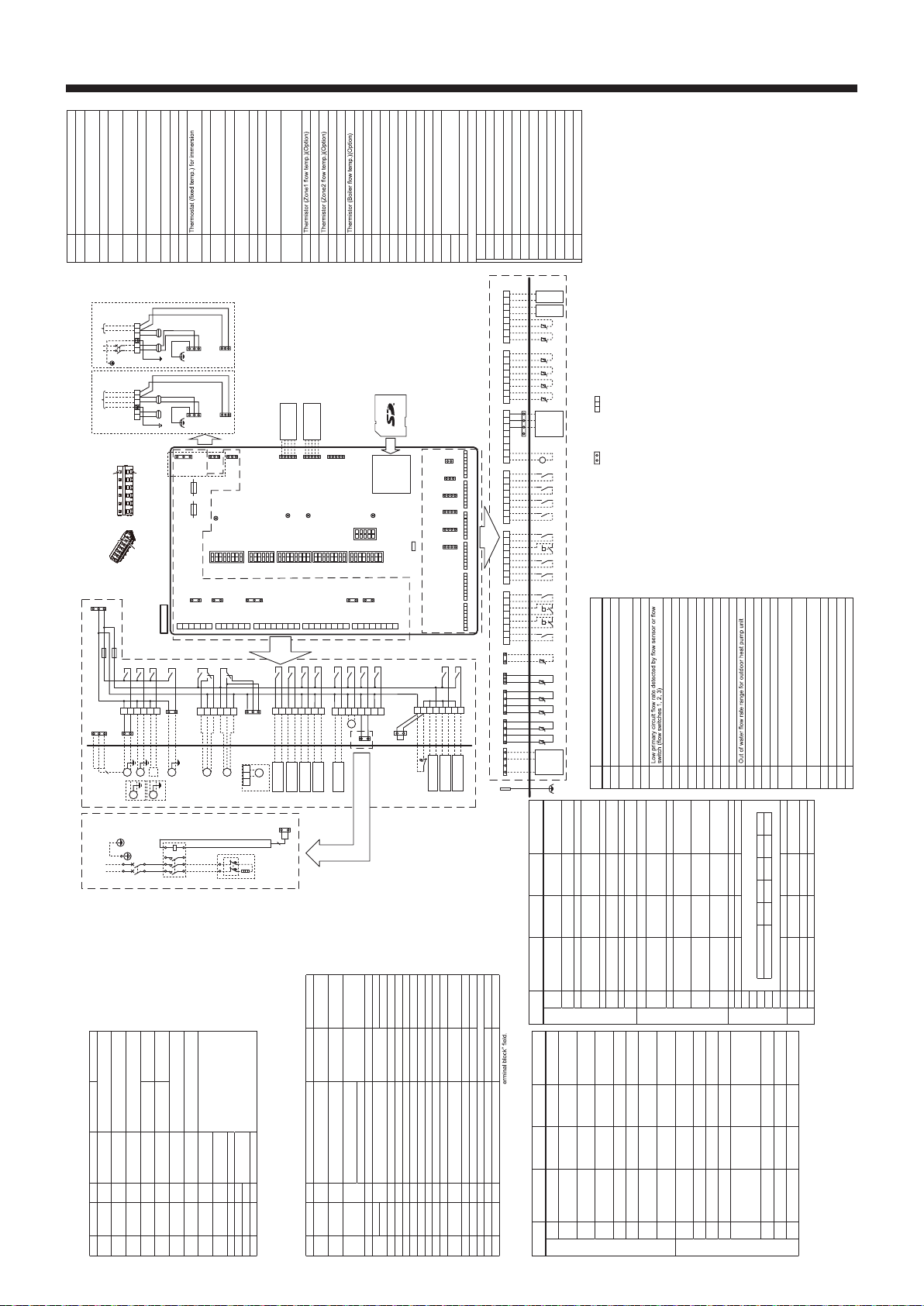
15
Wiring Diagram
FTC WIRING DIAGRAM <PAC-IF07*B-E> Symbol Name
TB1 Terminal block <Power supply, Outdoor unit>
ECB2
Earth leakage circuit breaker for immersion heater
(Except PAC-IF071B-E)
MP1
Water circulation pump 1(Space heating & DHW)
MP2 Water circulation pump 2
(Space heating for Zone1)(Local supply)
MP3 Water circulation pump 3
(Space heating for Zone2)(Local supply)
MP4
Water circulation pump 4 (DHW)(Local supply)
3WV
(2WV1) 3-way valve (2-way valve 1)(Local supply)
2WV2a 2-way valve (For Zone 1)(Local supply)
2WV2b 2-way valve (For Zone 2)(Local supply)
MXV Mixing valve (Local supply)
IHT heater(Except PAC-IF071B-E)
IH Immersion heater(Except PAC-IF071B-E)
IHC Contactor for immersion heater
(Except PAC-IF071B-E)
TH1 Thermistor (Room temp.)(Option)
TH2 Thermistor (Ref. liquid temp.)
(Included in PAC-IF071B-E)
THW1 Thermistor (Flow water temp.)
THW2 Thermistor (Return water temp.)
THW5A Thermistor (DHW tank upper water temp.)
(Included in PAC-IF073B-E)
THW5B Thermistor (DHW tank lower water temp.)
(Included in PAC-IF073B-E)
(Option for PAC-IF071/072B-E)
THW6
THW7 Thermistor (Zone1 return temp.)(Option)
THW8
THW9 Thermistor (Zone2 return temp.)(Option)
THW10 Thermistor (Mixing tank temp.)(Option)
THWB1
IN1 Room thermostat 1 (Local supply)
IN2 Flow switch 1 (Local supply)
IN3 Flow switch 2 (Local supply)
IN4 Demand control (Local supply)
IN5 Outdoor thermostat (Local supply)
IN6 Room thermostat 2 (Local supply)
IN7 Flow switch 3 (Local supply)
IN8 Electric energy meter 1 (Local supply)
IN9 Electric energy meter 2 (Local supply)
IN10 Heat meter (Local supply)
IN11 Smart grid ready input (Local supply)
IN12
INA1 Flow sensor (Option)
FLOW TEMP. CONTROLLER (FTC)
TBO.1-5
Terminal block <Outputs>
TBI.1-6 Terminal block <Signal Inputs, Thermistor>
F1 Fuse (IEC T10AL250V)
F2 Fuse (IEC T6.3AL250V)
SW1-6 DIP switch *See Table 3
X1-16 Relay
LED1 Power supply (FTC)
LED2 Power supply (Main remote controller)
LED3 Communication (FTC-Outdoor unit)
LED4 Reading or writing data to SD card
CNPWM
Pump speed control signal for MP1
CN108 SD card connector
1. Symbols used in wiring diagram are, : connector, : terminal block. Function with asterisk (*) may not be available depending on model types.
2. Indoor unit and outdoor unit connecting wires have polarities, make sure to match terminal numbers (S1, S2, S3) for correct wirings.
3. Since the outdoor unit side electric wiring may change, be sure to check the outdoor unit electric wiring diagram for service.
4. When connecting a booster heater, the wiring method is different according to the type of built-in thermostat.
Please refer to the installation manual for details.
Table 4 Error Codes
Code Error
L3 Circulation water temperature overheat protection
L4 DHW tank water temperature overheat protection
L5 Indoor unit temperature thermistor (THW1, THW2, THW5B,
THW6, THW7, THW8, THW9) failure
L6 Circulation water freeze protection
L8 Heating operation error
L9
LA Pressure sensor failure
LB High pressure protection
LC Boiler circulation water temperature overheat protection
LD
Boiler temperature thermistor (THWB1) failure
LE Boiler operation error
LF Flow sensor failure
LH Boiler circulation water freeze protection
LJ DHW operation error (type of external plate HEX)
LL Setting errors of DIP switches on FTC control board
LP
P1 Thermistor (Room temp.) (TH1) failure
P2 Thermistor (Ref. liquid temp.) (TH2) failure
P6 Anti-freeze protection of plate heat exchanger
J0 Communication failure between FTC and wireless receiver
J1 - J8
Communication failure between wireless receiver and
wireless remote controller
J9
Communication failure between FTC (Master) and FTC
(Slave)
E0 - E5 Communication failure between main remote controller and
FTC
E6 - EF
Communication failure between FTC and outdoor unit
E9 Outdoor unit receives no signal from indoor unit.
EE Outdoor unit incorrect connection
U*, F*,A*
Outdoor unit failure
Table 1 Signal Inputs
Name
Terminal block
Connector
Item OFF (Open) ON (Short)
IN1 TBI.1 7-8 — Room thermostat
1 input *1 Refer to SW2-1 in
<Table 3 DIP Switch Functions>.
IN2 TBI.1 5-6 — Flow switch 1
input Refer to SW2-2 in
<Table 3 DIP Switch Functions>.
IN3 TBI.1 3-4 — Flow switch 2
input (Zone1) Refer to SW3-2 in
<Table 3 DIP Switch Functions>.
IN4 TBI.1 1-2 — Demand control
input Normal Heat source OFF/
Boiler operation *3
IN5 TBI.2 7-8 — Outdoor thermo-
stat input *2 Standard opera-
tion Heater operation/
Boiler operation *3
IN6 TBI.2 5-6 — Room thermostat
2 input *1 Refer to SW3-1 in
<Table 3 DIP Switch Functions>.
IN7 TBI.2 3-4 — Flow switch 3
input (Zone2) Refer to SW3-2 in
<Table 3 DIP Switch Functions>.
IN8 TBI.3 7-8 — Electric energy
meter 1
Refer to installation manual.
IN9 TBI.3 5-6 — Electric energy
meter 2
IN10
TBI.2 1-2 — Heat meter
IN11
TBI.3 3-4 — Smart grid ready
input
IN12
TBI.3 1-2 —
INA1
TBI.4 1-3 CN1A Flow sensor
*1. Set the ON/OFF cycle time of the room thermostat for 10 minutes or more;
otherwise the compressor may be damaged.
*2. If using outdoor thermostat for controlling operation of heaters, the lifetime of the
heaters and related parts may be reduced.
*3. To turn on the boiler operation, use the main remote controller to select “Boiler” in
“External input setting” screen in the service menu.
Table 2 Outputs
Name
Terminal block
Connector
Item OFF ON
OUT1
TBO.1 1-2 CNP1 Water circulation pump 1 output
(Space heating/cooling & DHW) OFF ON
OUT2
TBO.1 3-4 — Water circulation pump 2 output
(Space heating/cooling for Zone1) OFF ON
OUT3
TBO.1 5-6 — Water circulation pump 3 output
(Space heating/cooling for Zone2) *1 OFF ON
2-way valve 2b output *2
OUT4
TBO.2 4-6 CNV1 3-way valve (2-way valve) output Heating DHW
OUT5
TBO.2 1-2 — Mixing valve output *1 Stop Close
TBO.2 2-3 Open
OUT6
TBO.5 5-6 — Booster heater 1 output OFF ON
OUT7
TBO.5 7-8 — Booster heater 2 output OFF ON
OUT8
TBO.4 7-8 — Cooling signal output OFF ON
OUT9
TBO.4 5-6 CNIH Immersion heater output OFF ON
OUT10
TBO.3 1-2 — Boiler output OFF ON
OUT11
TBO.3 5-6 — Error output Normal Error
OUT12
TBO.3 7-8 — Defrost output Normal Defrost
OUT13
TBO.4 3-4 — 2-way valve 2a output *2 OFF ON
OUT14
— CNP4 Water circulation pump 4 output
(DHW) OFF ON
OUT15
TBO.4 1-2 — Comp. ON signal OFF ON
OUT16
TBO.3 3-4 — Thermo ON signal OFF ON
OUTA1
TBI.4 7-8 — Analog output 0V-10V
BC
TBO.5 3-4 — Booster heater protection output
OFF(BHT Open) ON(BHT Short)
BHT
TBO.5 1-2
CNBHT
Thermostat for booster heater
Thermostat normal: Short High temp. open
Do not connect to the terminals that are indicated as “—” in the “T
*1. For 2-zone temperature control.
*2. For 2-zone valve ON/OFF control.
CN108
CN01
(BK)
1
3
CN3C
(BU)
1
3
CNPWM
(WH)
1
5
CNRF
(WH) Wireless receiver
(Option)
1
5
CN105
(RD) WiFi adapter
(Option)
1
5
CNIT
(BU)
1
2
CN20
(RD)
1
3
CN21
(YE)
1
4
CNW12
(RD)
CNW5
(BU)
1
4
CN1A
(WH)
TBI.1
LED1
LED2
LED3
LED4
TAB1
1
8
1
8
1
8
1
8
1
6
SW1
SW2
SW3
SW4
SW5
F1
IEC T10AL250V
F2
IEC T6.3AL250V
1
2
3
4
5
6
1
2
3
4
5
6
1
2
3
4
5
6
7
8
1
2
3
4
5
6
7
8
1
3
1
3
CNBHT
(BK)
CNIH
(OG)
CNV1
(WH)
CNP4
(RD)
CNP1
(WH)
TBO.1
TBO.2
TBO.3
TBO.4
1
2
3
4
5
6
7
8
TBO.5
1
3
5
1
3
CNP4
(RD)
F1
F2
CN01
(BK)
TBO.1 X1
X2
X3
X14
1
3
3
CNPWM
(WH)
CNP1
(WH)1
3
M
1~
2WV2b
MP3
MP4
1
2
3
4
5
6
TBO.2
1
3
5
CNV1
(WH)
3WV
1
2
3
4
5
6
7
8
TBO.3
X4
X10
X16
X11
X12
TBO.4
1
2
3
4
5
6
7
8
TBO.5
X15
X13
X9
X8
Signal output
(Boiler)
Signal output
(thermo on)
Signal output
(Error)
Signal output
(Defrost)
Signal output
(Comp. on)
CNIH
(OG) 2WV2a
1
3
X6
X7
N
(3)
L
(1)
42
BU
RD
315
A1
426
A2
IHT
IH
BA
BU
RD
1
3
2CNIH
(OG)
OG
OG
Power supply
to Immersion heater
(Except PAC-IF071B-E)
~/N 230V 50Hz
ECB2
IHC
1
5
3
1
5
3
1
3
1
3
FTC board
X5B
X5A
MXV
Close
N
Open
MP2
MP1
M
1~
M
1~
TBI.2 TBI.3 TBI.4 TBI.5 TBI.6
1234567812345678123456781234567812345678 12345678
1
2
3
4
5
6
1
4
t° t° t°
12345678
IN4IN3IN2IN1
12345678
IN10IN7IN6IN5
12345678
IN12IN9IN8 IN11
12345678
OUTA1
Flow
Sensor
12345678
t°
THW6 THW7 THW8 THW9
t° t°
12345678
THWB1 THW10
Main remote
controller
FTC
(Slave)
TBI.1 TBI.2 TBI.3 TBI.4 TBI.5 TBI.6
CN20
(RD)
t°
CN21
(YE)
13
12
CNW12
(RD)
14
CNW5
(BU)
t°
TAB1
THTH1TH2 *
THW5B *
-+ +-
V
-+-+
14
t° t°t°
THW2THW1
1
5
SW6
M
1~
M
1~
M
1~
M
1~
M
1~
NL
S3S2S1
NL
S3S2S1
To outdoor
unit
TB1
OG OG
YE
YE
GNYE
To outdoor
unit
Power supply
~/N 230V 50Hz
TB1
OG
BU
RD
BU
RD
YE
GNYE
1
3
1
3
OG
BN OG
BN
Indoor unit powered
by independent source
Indoor unit powered
via outdoor unit
CIRCUIT
BREAKER
1
3
5
CN3C
(BU)
CN3C
(BU)
CN01
(BK)
OG
YE
1
3
5
CN01
(BK)
2WV1
M
1~
4 5 6
TBO.2
1
2
3
4
5
6
7
8
Signal output for booster
heater protection
Signal output
(booster heater 1)
Signal output
(booster heater 2)
CN1A
(WH)
14
<How to useTBO.1 to 5>
14
Pressre
Sensor *
CN401
(WH)
1
4
CN401
(WH)
t°
THW5A *
1
BHT
CNBHT
(BK)
3
Tool Tool
Conductor Conductor
Outline view Top view
Connect them using either way as shown below.
*1. External output (OUT11) will be available. For safety reasons, this function is not available for certain errors. (In that case, system operation must be stopped and only the
water circulation pump keeps running.)
*2. This switch functions only when the FTC unit is connected with a PUHZ-FRP outdoor unit. When another type of outdoor unit is connected, the heating mode function is
active regardless of the fact that this switch is ON or OFF.
*3. Space heating and DHW can be operated only in indoor unit, like an electric heater.
*4. If emergency mode is no longer required, return the switch to OFF position.
*5. Active only when SW3-6 is set to OFF.
*6. Active only when SW4-1 is set to ON.
Table 3 DIP switch functions
DIP switch Function OFF ON Default settings:
Indoor unit model
SW1
SW1-1
Boiler WITHOUT
Boiler WITH Boiler OFF
SW1-2
Heat pump maxi-
mum outlet water
temperature 55ºC 60ºC ON
SW1-3
DHW tank WITHOUT
DHW tank WITH DHW
tank
OFF : PAC-IF071B-E
ON : Except
: PAC-IF071B-E
SW1-4
Immersion heater WITHOUT Im-
mersion heater WITH Immer-
sion heater
OFF : PAC-IF071B-E
ON : Except
: PAC-IF071B-E
SW1-5
Booster heater WITHOUT
Booster heater WITH Booster
heater
OFF
SW1-6
Booster heater
function For heating
only For heating
and DHW
OFF
SW1-7
Outdoor unit type Split type Packaged type
OFF : PAC-IF071B-E
ON : Except
: PAC-IF071B-E
SW1-8
Wireless remote
controller WITHOUT
Wireless re-
mote controller
WITH Wireless
remote control-
ler OFF
SW2
SW2-1
Room thermostat 1
input (IN1) logic
change
Zone1 opera-
tion stop at ther-
mostat short
Zone1 opera-
tion stop at ther-
mostat open
OFF
SW2-2
Flow switch 1 input
(IN2) logic change Failure detec-
tion at short Failure detec-
tion at open OFF
SW2-3
Booster heater
capacity restriction Inactive Active OFF
SW2-4
Cooling mode func-
tion Inactive Active OFF
SW2-5
Automatic switch to
backup heat source
operation (When
outdoor unit stops
by error)
Inactive Active *1 OFF
SW2-6
Mixing tank WITHOUT Mix-
ing tank WITH Mixing
tank OFF
SW2-7
2-zone temperature
control Inactive Active *5 OFF
SW2-8
Flow sensor WITHOUT
Flow sensor WITH Flow
sensor OFF
DIP switch Function OFF ON Default settings:
Indoor unit model
SW3
SW3-1
Room thermostat
2 input (IN6) logic
change
Zone2 opera-
tion stop at ther-
mostat short
Zone2 opera-
tion stop at ther-
mostat open
OFF
SW3-2
Flow switch 2 and 3
input logic change Failure detec-
tion at short Failure detec-
tion at open OFF
SW3-3
— — — OFF
SW3-4
Electric energy
meter WITHOUT
Electric energy
meter WITH Electric
energy meter OFF
SW3-5
Heating mode function *2
Inactive Active ON
SW3-6
2-zone valve ON/
OFF control Inactive Active OFF
SW3-7
Heat exchanger for DHW
Coil in tank
External plate HEX
OFF
SW3-8
Heat meter WITHOUT
Heat meter WITH Heat
meter OFF
SW4
SW4-1
Multiple outdoor control
Inactive Active OFF
SW4-2
Position of multiple
outdoor units
control *6 Slave Master OFF
SW4-3
— — — OFF
SW4-4
Indoor unit only
operation (during
installation work) *3 Inactive Active OFF
SW4-5
Emergency mode
(Heater only opera-
tion) Normal
Emergency mode
(Heater only
operation)
OFF *4
SW4-6
Emergency mode
(Boiler operation) Normal Emergency
mode
(Boiler operation)
OFF *4
SW5
SW5-1
— — — OFF
SW5-2
Advanced auto adaptation
Inactive Active ON
SW5-3
Capacity code
SW5-3 SW5-4 SW5-5 SW5-6 SW5-7
PAC-IF07*B-E OFF OFF OFF OFF OFF
SW5-4
SW5-5
SW5-6
SW5-7
SW5-8
— — — OFF
SW6
SW6-1
— ——
OFF : PAC-IF071/072B-E
ON : PAC-IF073B-E
SW6-3
Pressure sensor Inactive Active OFF
SW6-4
Analog output Inactive Active OFF

16
Electrical Work
regulations.
FTC (Master) powered by independent source
If FTC (Master) and outdoor units have separate power supplies, the following
requirements MUST be carried out:
• FTC (Master) unit electrical box connector connections changed.
• Outdoor unit DIP switch settings changed to SW8-3 ON.
• Turn on the outdoor unit before the FTC (Master).
• Power by independent source is not available for particular models of outdoor
unit model.
For more details refer to the connecting outdoor unit installation manual.
1. High voltage cables (OUTPUT)
2. High voltage cables (OUTPUT)
3. Low voltage cables (INPUT) and wireless receiver’s cable
4. Thermistor cables
5. Power cables
Wiring for PAC-IF07*B-E Notes:
1. Do not run the low voltage cables through a slot that the high voltage
cables go through.
2. Do not run other cables except low voltage cables through a slot that
the wireless receiver’s cable goes through.
3. Do not bundle power cables together with other cables.
4. Bundle cables as gure above by using clamps.
FTC (Master) power supply ~/N 230 V 50 Hz
FTC (Master) input capacity
Main switch (Breaker) *1 16 A
Wiring
Wiring No.
xsize (mm²)
FTC (Master) power supply 2 × Min. 1.5
FTC (Master) power supply earth 1 × Min. 1.5
FTC (Master) - Outdoor unit *2 2 × Min. 0.3
FTC (Master) - Outdoor unit earth —
Circuit
rating
FTC (Master) L - N *3 230V AC
FTC (Master) - Outdoor unit S1 - S2 *3 —
FTC (Master) - Outdoor unit S2 - S3 *3 24V DC
Electrical connections 1 phase/3 phase
*1. If the installed earth leakage circuit breaker does not have an over-current protection function,install a breaker
with that function along the same power line.
A breaker with at least 3.0 mm contact separation in each pole shall be provided. Use earth leakage breaker (NV).
The breaker shall be provided to ensure disconnection of all active phase conductors of the supply.
Note: In accordance with IEE regulations, the circuit breaker/isolating switch located on the outdoor unit should be installed with
lockable devices (health and safety).
*2. Max. 120m
*3. The values given in the table above are not always measured against the ground
value.
Notes: 1. Wiring size must comply with the applicable local and national codes.
2. FTC (Master) unit/outdoor unit connecting cords shall not be lighter
than polychloroprene sheather exible cord. (Design 60245 IEC57)
FTC (Master) unit power supply cords shall not be lighter than
polychloroprene sheathed exible cord. (Design 60227 IEC 53)
3. Install an earth longer than other cables.
4. Please keep enough output capacity of power supply for each
individual heater. Insucient power supply capacity might cause
chattering.
S1
S2
S3
L
N
L
N
CN01
CN01
CN01
CN01
S1
S2
S3
Initial settings
(Power supplied by
outdoor unit)
(Separate power
supply to the cylinder
unit)
FTC
(Master)
FTC
(Master)
Black
BLACK
BLACK YELLOW
BLACK
YELLOW YELLOW
YELLOW BLACK
Black
Fig. 19
TB2
Clamps
Slot
TB1
Clamps
1 2 3 4 5
Clamps
Clamps
*1
*1
: PAC-IF071B-E
: PAC-IF072/073B-E
Power
supply
3N~
400V
50Hz
Earth
leakage
breaker
Wiring
circuit
breaker
or
Isolating
switch
L3
L2
L1
N
S1
S2
S3
Outdoor unit
S1
S2
S3
TB2
TB1
L
N
ECB
Wiring
circuit
breaker
or
Isolating
switch
To control
board
ELB for
immersion
heater
(DHW tank)
L
N
Power
supply
~/N
230V
50Hz
Earth
leakage
breaker
Wiring
circuit
breaker
or
Isolating
switch
circuit
circuit
FTC (Master)
Power
supply
~/N
230V
50Hz
<3 phase>
Power
supply
~/N
230V
50Hz
Earth
leakage
breaker
*1
*1
Wiring
circuit
breaker
or
Isolating
switch
L
NS1
S2
S3
Outdoor unit
S1
S2
S3
TB2
TB1
L
N
ECB
Wiring
circuit
breaker
or
Isolating
switch
To control
board
ELB for
immersion
heater
(DHW tank)
L
N
Power
supply
~/N
230V
50Hz
Earth
leakage
breaker
Wiring
circuit
breaker
or
Isolating
switch
Power
supply
circuit
circuit
FTC (Master)
~/N
230V
50Hz
<1 phase>

17
Electrical Work
Connecting inputs/outputs
Signal inputs
Name Terminalblock Connector Item OFF (Open) ON (Short)
IN1 TBI.1 7-8 — Room thermostat 1 input *1 Refer to SW2-1
IN2 TBI.1 5-6 — Flow switch 1 input Refer to SW2-2
IN3 TBI.1 3-4 — Flow switch 2 input (Zone1) Refer to SW3-2
IN4 TBI.1 1-2 —Demand control input Normal Heat source OFF/ Boiler operation *3
IN5 TBI.2 7-8 — Outdoor thermostat input *2 Standardoperation Heater operation/ Boiler operation *3
IN6 TBI.2 5-6 — Room thermostat 2 input *1 Refer to SW3-1
IN7 TBI.2 3-4 — Flow switch 3 input (Zone2) Refer to SW3-2
IN8 TBI.3 7-8 —Electric energy meter 1 *4
IN9 TBI.3 5-6 — Electric energy meter 2
IN10 TBI.2 1-2 — Heat meter
IN11 TBI.3 3-4 — Smart grid ready input *5
IN12 TBI.3 1-2 —
INA1 TBI.4 1-3 CN1A Flow sensor input *6
*1. Set the ON/OFF cycle time of the room thermostat for 10 minutes or more; otherwise the
compressor may be damaged.
*2. If using outdoor thermostat for controlling operation of heaters, the lifetime of the heaters and
related parts may be reduced.
*3. To turn on the boiler operation, use the main remote controller to select “Boiler” in “External input
setting“ screen in the service menu.
*4. Connectable electric energy meter and heat meter
• Pulse type Voltage free contact for 12V DC detection by FTC
(TBI.2 1 pin, TBI.3 5 and 7 pins have a positive voltage.)
• Pulse duration Minimum ON time: 40ms
Minimum OFF time: 100ms
• Possible unit of pulse 0.1 pulse/kWh 1 pulse/kWh 10 pulse/kWh
100 pulse/kWh 1000 pulse/kWh
Those values can be set by the main remote controller. (Refer to the menu tree in “7.2 Main remote controller”.)
*5. As for the smart grid ready, refer to “4.9 Smart grid ready”.
• Power supply 5V DC
• Measuring range 5 to 100 L/min.
Those values can be set by the main remote controller.
(Refer to <Auxiliary settings> on this page.)
Wiring specication and local supply parts
Item Name Model and specications
Signal input function Signal input wire Use sheathed vinyl coated cord or cable.
Max.30m
Wiretype:
Wire size: CV, CVS or equivalent
Stranded wire 0.13 mm² to 0.52 mm²
Solid wire: ø0.4 mm to ø0.8 mm
Switch Non-voltage “a” contact signals
Remote switch: minimum applicable load 12V DC, 1mA
Note: Stranded wire should be processed with insulation-covered bar terminal (DIN46228-4 standard compatible type).
<Auxiliary settings>
This function is used to set the parameters for any auxiliary parts used in the system
Menu subtitle Function/Description
Economy settings for pump Water pump stops automatically in certain period of time from when operation is nished.
Delay Time before pump switched off*
Electric heater (Heating) To select “WITH booster heater (ON)” or “WITHOUT booster heater (OFF)” in Heating mode.
Delay The minimum time required for the booster heater to turn ON from after Heating mode has started.
Electric heater (DHW) To select “WITH (ON)” or “WITHOUT (OFF)” booster heater or immersion heater individually in DHW mode.
Delay The minimum time required for the booster heater or immersion heater to turn ON from after DHW mode has started. (This setting is applied for both booster and
immersion heater.)
Mixing valve
control *2 Running Period from valve fully open (at a hot water mixing ratio of 100%) to valve fully closed (at a cold water mixing ratio of 100%).
Interval Interval (min.) to control the Mixing valve.
Flowsensor Minimum The minimum ow rate to be detected at Flow sensor.
Maximum The maximum ow rate to be detected at Flow sensor.
interval to 2 minutes that is a default value. With the interval set longer, it could take longer to warm up a room.
CN108
CN01
(BK)
1
3
CN3C
(BU)
CNPWM
(WH)
1
5
CNRF
(WH)
CN105
(RD)
CNIT
(BU)
1
2
CN20
(RD)
TBI.1
LED3
LED4
TAB1
8
1
2
3
4
5
6
1
2
3
4
5
6
7
8
CNP1
(WH)
TBO.1 1
5
3
1
5
SW6
1
3
1
5
1
5
LED2
1
SW1
8
1
SW2
8
1
SW3
1
SW4
6
8
1
SW5 LED1
1
3
1
3
CNP4
(RD)
TBO.2
1
2
3
4
5
6
TBO.3 CNV1
(WH)
1
3
5
1
2
3
4
5
6
7
8
TBO.4
CNIH
(OG)
1
3
CNBHT
(BK)
1
3
CN21
(YE)
1
3
CNW12
(RD)
1
4
CNW5
(BU)
1
4
1
4
CN1A
(WH)
68 7 54 3 21TBI.2
68 7 54 3 21TBI.3
68 7 54 3 21TBI.4
68 7 54 3 21TBI.5
68 7 54 3 21 68 7 54 3 21
TBI.6
1
4
CN401
(WH)
F2 F1
1
2
3
4
5
6
7
8
TBO.5
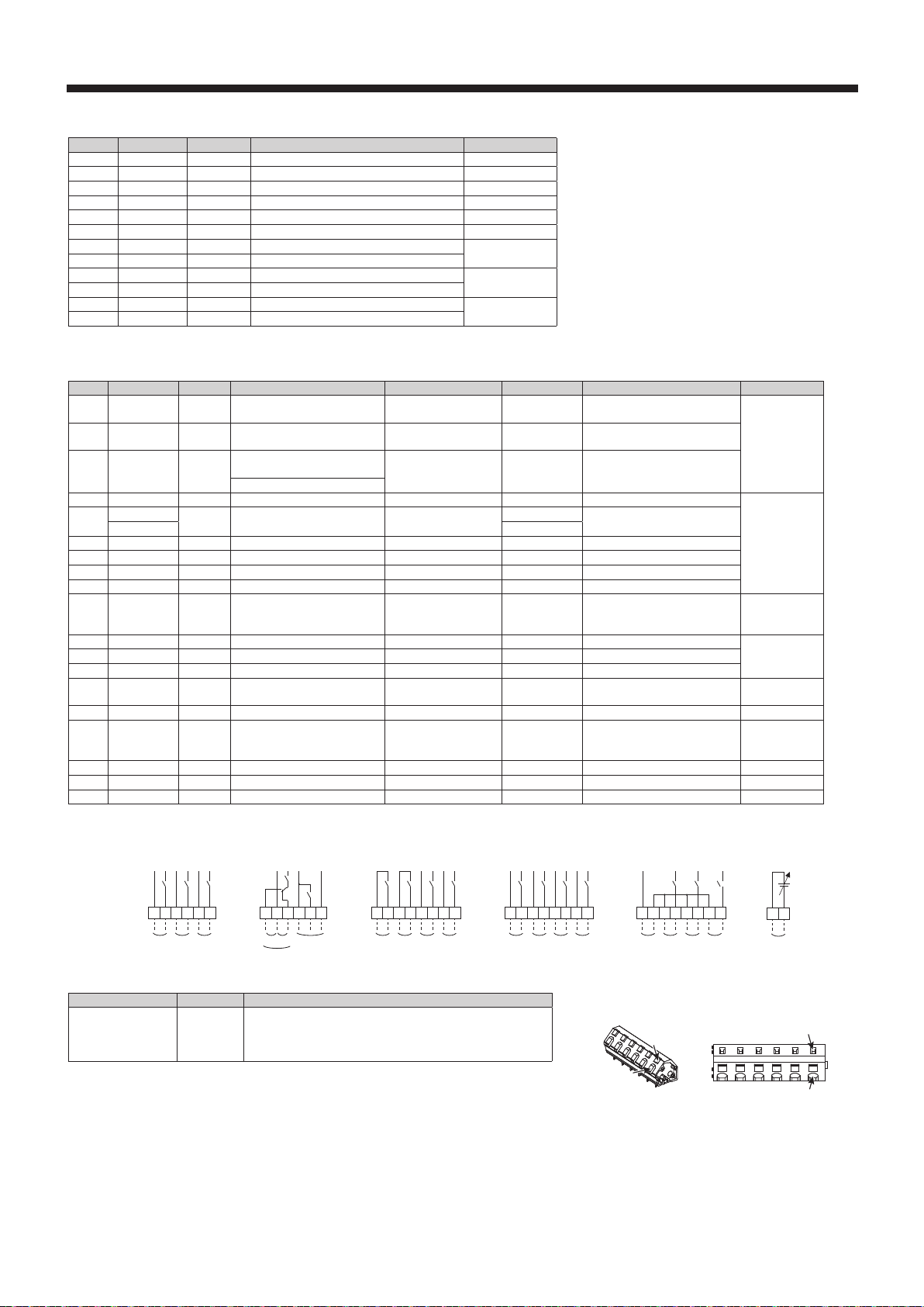
18
Electrical Work
inputs
Name Terminalblock Connector Item OFF (Open)
TH1 —CN20 Thermistor (Room temp.) (Option) *1 PAC-SE41TS-E
TH2 —CN21 Thermistor (Ref. liquid temp.) *2 —
THW1 —CNW12 1-2 Thermistor (Flow water temp.) —
THW2 —CNW12 3-4 Thermistor (Return water temp.) —
THW5A — CNW5 1-2 Thermistor (DHW tank upper water temp.) —
THW5B — CNW5 3-4 Thermistor (DHW tank water temp.) —
THW6 TBI.5 7-8 —Thermistor (Zone1 ow water temp.) (Option) *1 PAC-TH011-E
THW7 TBI.5 5-6 — Thermistor (Zone1 return water temp.) (Option) *1
THW8 TBI.5 3-4 — Thermistor (Zone2 ow water temp.) (Option) *1 PAC-TH011-E
THW9 TBI.5 1-2 — Thermistor (Zone2 return water temp.) (Option) *1
THWB1 TBI.6 7-8 —Thermistor (boiler ow water temp.) (Option) *1 PAC-TH012HT(L)-E
THW10 TBI.6 5-6 — Thermistor (Mixing tank water temp.) (Option) *1
Onputs
Name Terminalblock Connector Item OFF ON Signal/Max. current Max. total current
OUT1 TBO.1 1-2 CNP1 Water circulation pump 1 output
(Space heating/cooling & DHW) OFF ON 230V AC 1.0A Max. (Inrush current
40A Max.)
4.0A (a)
OUT2 TBO.1 3-4 —Water circulation pump 2 output
(Space heating/cooling for Zone1) OFF ON 230V AC 1.0A Max. (Inrush current
40A Max.)
OUT3 TBO.1 5-6 — Water circulation pump 3 output
(Space heating/cooling for Zone2) *1 OFF ON 230V AC 1.0AMax. (Inrush current
40AMax.)
2-way valve 2b output *2
OUT4 TBO.2 4-6 CNV1 3-way valve (2-way valve 1) output Heating DHW 230VAC 0.1AMax.
3.0A(b)
OUT5 TBO.2 1-2 — Mixing valve output *1 Stop Close 230VAC 0.1A Max.
TBO.2 2-3 Open
OUT6 TBO.5 5-6 —Booster heater 1 output OFF ON 230V AC 0.5A Max. (Relay)
OUT7 TBO.5 7-8 —Booster heater 2 output OFF ON 230V AC 0.5A Max. (Relay)
OUT8 TBO.4 7-8 —Cooling signal output OFF ON 230V AC 0.5A Max.
OUT9 TBO.4 5-6 CNIH Immersion heater output OFF ON 230V AC 0.5A Max. (Relay)
OUT10 TBO.3 1-2 —Boiler output OFF ON Non-voltagecontact
220 - 240V AC (30 V DC)
0.5A or less 10mA 5V DC or more —
OUT11 TBO.3 5-6 —Error output Normal Error 230V AC 0.5A Max. 3.0A (b)OUT12 TBO.3 7-8 —Defrost output Normal Defrost 230V AC 0.5A Max.
OUT13 TBO.4 3-4 — 2-way valve 2a output *2 OFF ON 230V AC 0.1A Max.
OUT14 — CNP4 Water circulation pump 4 output
(DHW) OFF ON 230V AC 1.0AMax. 4.0A(a)
OUT15 TBO.4 1-2 — Comp. ON signal OFF ON 230V AC 0.5AMax. 3.0A(b)
OUT16 TBO.3 3-4 — Heating/Cooling thermo ON signal OFF ON Non-voltage contact
220 - 240VAC (30V DC)
0.5Aor less 10mA 5V DC or more —
OUTA1 TBI.4 7-8 — Analog output — — 0 - 10V DC 5mAMax. —
BC TBO.5 3-4 — Booster heater protection output OFF (BHT open) ON (BHT short) 230VAC 0.5A Max. —
BHT TBO.5 1-2 CNBHT Thermostat for booster heater Thermostat Normal:short High temp.: open — —
Do not connect to the terminals that are indicated as “—” in the “Terminal block" eld.
*1 For 2-zone temperature control.
*2 For 2-zone valve ON/OFF control.
LN
OUT9
LN
OUT15
L
1 2 3456
TBO.1
1 2 3456
TBO.2 TBO.3 1 2 3456 7 8 1 2 346
5
TBO.4
LLL NNN
OUT1 OUT2 OUT3
N L L N
OUT5
OUT4
N L N L
OUT10 OUT16OUT11OUT12
N
TBO.5 1 2 3456 7 8
L L L
BHT BC OUT6 OUT7
N
OUT13
LN
OUT8
8
7TBI.4 87
OUTA1
Close Open
Wiring specication and local supply parts
Item Name Model and Specication
External output function Outputs wire
Use sheathed vinyl coated cord or cable. Max. 30m
Wire type: CV, CVS or equivalent
Wire size: Stranded wire 0.25mm² to 1.5mm²
Solid wire: 0.25mm² to 1.5mm²
Note:
1. When the FTC is powered via outdoor unit, the maximum grand total
current of (a)+(b) is 3.0A.
2. Do not connect multiple water circulation pumps directly to each output
(OUT1, OUT2 and OUT3). In such a case, connect them via (a) relay(s).
3. Connect an appropriate surge absorber to OUT10 (TBO.3 1-2) depending
on the load at site.
4. Stranded wire should be processed with insulation-covered bar terminal
(DIN46228-4 standard compatible type).
Connect them using either way as shown above.
How to use TBO.1 to 5
Tool Tool
Conductor Conductor
Outline view Top view
Ensure to wire thermistor wirings away from the
power line and/or OUT1 to 16 wirings.
*1. The maximum length of the thermistor wiring is
30m.
The length of the optional thermistors are 5m.
If you need to splice and extend the wirings,
following points must be carried out.
1) Connect the wirings by soldering.
2) Insulate each connecting point against
dust and water. Stranded wire should be
processed with insulation-covered bar
terminal (DIN46228-4 standard compatible
type).
*2. Except PAC-IF072/073B-E

19
System Set Up
DIP Switch Functions
Located on the FTC printed circuit board are 6 sets of small white
switches known as DIP switches. The DIP switch number is printed on the
circuit board next to the relevant switches. The word ON is printed on the
circuit board and on the DIP switch block itself. To move the switch you
will need to use a pin or the corner of a thin metal ruler or similar.
DIP switch settings are listed below in the table. Only an authorised
installer can change DIP switch settings under one's own responsibility
unit and outdoor unit power supplies before changing the switch settings.
DIP switch Function OFF ON Default settings: Indoor unit model
SW1 SW1-1 Boiler WITHOUT Boiler WITH Boiler OFF
SW1-2 Heat pump maximum outlet water temperature 55ºC 60ºC ON
SW1-3 DHW tank WITHOUT DHW tank WITH DHW tank ON
SW1-4 Immersion heater WITHOUT Immersion heater WITH Immersion heater ON
SW1-5 Booster heater WITHOUT Booster heater WITH Booster heater
OFF
SW1-6 Booster heater function For heating only For heating and DHW
OFF
SW1-7 Outdoor unit type Split type Packaged type
ON
SW1-8 Wireless remote controller WITHOUT Wireless remote controller WITH Wireless remote controller OFF
SW2 SW2-1 Room thermostat1 input (IN1) logic change
Zone1 operation stop at thermostat short Zone1 operation stop at thermostat open
OFF
SW2-2 Flow switch1 input (IN2) logic change Failure detection at short Failure detection at open OFF
SW2-3 Booster heater capacity restriction Inactive Active OFF
SW2-4 Cooling mode function Inactive Active OFF
SW2-5 Automatic switch to backup heat source operation
(When outdoor unit stops by error) Inactive Active *1 OFF
SW2-6 Mixing tank WITHOUT Mixing tank WITH Mixing tank OFF
SW2-7 2-zone temperature control Inactive Active *4 OFF
SW2-8 Flow sensor WITHOUT Flow sensor WITH Flow sensor ON
SW3 SW3-1 Room thermostat 2 input (IN6) logic change
Zone2 operation stop at thermostat short Zone2 operation stop at thermostat open
OFF
SW3-2 Flow switch 2 and 3 input logic change Failure detection at short Failure detection at open OFF
SW3-3 — — — OFF
SW3-4 Electric energy meter WITHOUT Electric energy meter WITH Electric energy meter OFF
SW3-5 Heating mode function Inactive Active ON
SW3-6 2-zone valve ON/OFF control Inactive Active OFF
SW3-7 — — — OFF
SW3-8 Heat meter WITHOUT Heat meter WITH Heat meter OFF
SW4 SW4-1
Multiple outdoor unit control Inactive Active
OFF
SW4-2
Position of multiple outdoor unit control Sub Main
OFF
SW4-3 — — — OFF
SW4-4
Indoor unit only operation (during installation work) *2
Inactive Active OFF
SW4-5 Emergency mode (Heater only operation) Normal
Emergency mode (Heater only operation)
OFF *3
SW4-6 Emergency mode (Boiler operation) Normal Emergency mode (Boiler operation) OFF *3
SW5 SW5-1 — — — OFF
SW5-2 Advanced auto adaptation Inactive Active ON
SW5-3 — — — OFF
SW5-4 — — — OFF
SW5-5 — — — OFF
SW5-6 — — — OFF
SW5-7 — — — OFF
SW5-8 — — — OFF
SW6 SW6-1 — — — OFF
SW6-2 — — — OFF
SW6-3 Pressure sensor Inactive Active OFF
SW6-4 Analog output signal (0-10V) Inactive Active OFF
SW6-5 — — — OFF
SW1
SW3
SW4
SW2
SW5
SW6
Notes: *1. External output (OUT11) will be available. For safety reasons, this function is not available for certain errors. (In that case, system operation must
be stopped and only the water circulation pump keeps running.)
*2. Space heating and DHW can be operated only in indoor unit, like an electric heater. (Refer to "5.7 Indoor unit only operation".)
*3. If emergency mode is no longer required, return the switch to OFF position.
*4. Active only when SW3-6 is set to OFF.

20
Logos
These Logos are the trademark of SD-3C, LLC
Capacities
2 GB to 32 GB *2
SD speed classes
All
*1 To edit main remote controller settings or to check operating
data, an Ecodan service tool (for use with PC) is required.
*2 A 2 GB SD memory card stores up to 30 days of operation logs.
store operating logs. *1
FTC (Main)
(a)
(b)
Using SD memory card
FTC is equipped with an SD memory card interface.
Using an SD memory card can simplify main remote controller
settings and can store operating logs. *1
<Handling precautions>
1. Use an SD memory card that complies with the SD standards.
Check that the SD memory card has a logo on it of those shown.
2. SD memory cards to the SD standards include SD, SDHC,
mini SD, mini SDHC, micro SD, and micro SDHC. The capacities
are available up to 32 GB. Choose that with a maximum
allowable temperature of 55ºC.
3. When the SD memory card is a mini SD, mini SDHC, micro SD,
or micro SDHC memory card, use an SD memory card converter
adapter.
4. Before writing to the SD
memory card, release the
write-protect switch.
5. Before inserting or ejecting an SD memory card, make sure
ejected with the system powered on, the stored data could be
corrupted or the SD memory card be damaged.
*An SD memory card is live for a while after the system is
following SD memory cards, however these operations are not
cards could change.
Manufacturer Model Tested in
Verbatim #44015 Mar. 2012
SanDisk SDSDB-002G-B35 Oct. 2011
Panasonic RP-SDP04GE1K Oct. 2011
Arvato 2GB PS8032 TSB 24nm MLC Jun. 2012
Arvato 2GB PS8035 TSB A19nm MLC Jul. 2014
SanDisk SDSDUN-008G-G46 Oct. 2016
Verbatim #43961 Oct. 2016
Verbatim #44018 Oct. 2016
VantasTek VSDHC08 Sep. 2017
Before using a new SD memory card (including the card that
comes with the unit), always check that the SD memory card can
be safely read and written to by the FTC controller.
<How to check read and write operations>
a) Check for correct wiring of power supply to the system.
(Do not power on the system at this point.)
b) Insert an SD memory card.
c) Power on the system.
d) The LED4 lamp lights if the read and write operations
are successfully completed. If the LED4 lamp continues
blinking or does not light, the SD memory card cannot be
read or written to by the FTC controller.
7. Make sure to follow the instruction and the requirement of the
SD memory card’s manufacturer.
8. Format the SD memory card if determined unreadable in step
(6). This could make it readable.
Download an SD card formatter from the following site.
SD Association homepage: https://www.sdcard.org
10. Mitsubishi Electric is not liable for any damages, in whole or
in part, including failure of writing to an SD memory card, and
corruption and loss of the saved data, or the like. Back up saved
data as necessary.
11. Do not touch any electronic parts on the FTC control board when
inserting or ejecting an SD memory card, or else the control
board could fail.
Installation - Wi-Fi adapter
be used to easily pair your Ecodan system to the internet to enable
remote control, monitoring, maintenance and technical support. The
Wi-Fi adapter is pre-wired to the FTC controller and is located at the
front of the cylinder.
The installer must locate and mount the Wi-Fi adapter in a suitable
location with good Wi-Fi signal strength (i.e. NOT within the FTC
controller and not nearby automatic control devices such as
reference guide provided. An instructional video is also available via
the QR code.
Scan the QR-Code for MELCloud access
points on Ecodan air source heat pumps
(a) For insertion, push on the SD memory card until it clicks
into place.
(b) For ejection, push on the SD memory card until it clicks.
Note: To avoid cutting ngers, do not touch sharp edges
of the SD memory card connector (CN108) on the
FTC control board.
System Set Up
This manual suits for next models
4
Table of contents
Popular Heater manuals by other brands

Fox Electronics
Fox Electronics GR2015-R instructions

Sealey
Sealey PEH9001 quick start guide

STIEBEL ELTRON
STIEBEL ELTRON ETC 170 A Operating and installation instructions

Vivax
Vivax QH-1203 user manual

Myson
Myson WHISPA III 9000 WM Installation, operating, maintenance and after sales manual

EWT
EWT Clima 902TLS manual


