Ecodense ROOF TOP Series Installation guide

14.12.2021 Rev. 03
www.ecodense.com
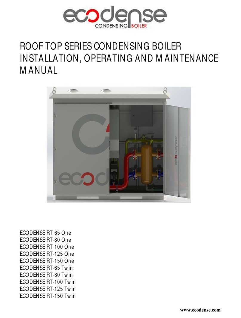
ROOFTOPSERIES CONDENSING BOILER
INSTALLATION,OPERATING ANDMAINTENANCE
MANUAL
ECODENSE RT-65 One ECODENSE RT-65 Twin
ECODENSE RT-80 One ECODENSE RT-80 Twin
ECODENSE RT-90 One ECODENSE RT-90 Twin
ECODENSE RT-100 One ECODENSE RT-100 Twin
ECODENSE RT-110 One ECODENSE RT-110 Twin
ECODENSE RT-115 One ECODENSE RT-115 Twin
ECODENSE RT-125 One ECODENSE RT-125 Twin
ECODENSE RT-150 One ECODENSE RT-150 Twin

14.12.2021 Rev. 03 1
DEAR USER,
The Roof Top Series Condensing Boilers ECODENSE RT-65 One, ECODENSE
RT-80 One, ECODENSE RT-90 One, ECODENSE RT-100 One, ECODENSE RT-110
One, ECODENSE RT-115 One, ECODENSE RT-125 One, ECODENSE RT-150 One,
ECODENSE RT-65 Twin, ECODENSE RT-80 Twin, ECODENSE RT-90 Twin,
ECODENSE RT-100 Twin, ECODENSE RT-110 Twin, ECODENSE RT-115 Twin,
ECODENSE RT-125 Twin, ECODENSE RT-150 Twin areconstructed andmanufactured
accordingto the most advance technological inventions and the safety rules. It is easy to
use for our customers.
We recommend that you read this manual and safetywarnings thoroughly before the
use of the device in order to ensuresafe, cost effective and environmental-friendly use.
If you encounterany issue that is not explained clearly inthis manual oryou could
not understand, please contact with our service department.
We thank you for choosing ECODENSE brand.
This Operating Manual is an integral partof the device andmust bemaintained in a
plastic dossier and hung at a clearly visible place bythe device.
TERMO ISI S STEMLER SAN.VE T C.A.Ş.
Esentepe Mah.MilangazCad. No:75 K:3
Kartal Monumento Plaza
Kartal/ STANBUL/TÜRK YE
Tel: +90 216 442 93 00
Fax: +90 216 370 45 03
www.ecodense.com
e-mail:servis@ecodense.com

14.12.2021 Rev. 03 2
CONTENTS
1. WARNINGS......................................................................................................................................... 3
1.1. Warning Symbols and Descriptions............................................................................................... 3
1.2. General Safety Rules...................................................................................................................... 4
2. TERMSOFWARRANTY................................................................................................................... 6
2.1. Out of Warranty Conditions........................................................................................................... 6
3. GENERAL CHARACTERISTICSOFCONDENSING BOILER...................................................... 7
3.1. ECODENSE Roof Top Series Condensing Boilers for Outdoor Installation................................ 8
3.2. TechnicalSpecifications................................................................................................................. 8
3.3. Boiler Safety................................................................................................................................... 8
3.4. Standart Equipments....................................................................................................................... 8
3.5. ECODENSE Roof Top Series Boiler Components........................................................................ 9
4. CONDENSING BOILER GAS, FLUE GASAND HEATING WATER SCHEMA........................ 11
5. CLOSED CIRCUIT COMPONENTS................................................................................................ 14
5.1. Balance Tank................................................................................................................................ 14
5.2. Sizing TableFor Expansion Tank................................................................................................ 15
5.3. ExpansionTank............................................................................................................................ 16
5.4. Manometer.................................................................................................................................... 16
5.5. Strainer......................................................................................................................................... 16
5.6. Air Separator................................................................................................................................ 16
6. WATER QUALITY............................................................................................................................ 17
7. TECHNICAL DATA.......................................................................................................................... 18
7.1. Capacity Table.............................................................................................................................. 18
7.2. Condensing BoilerDimensions.................................................................................................... 21
7.3. NoiseLevel................................................................................................................................... 22
8. INSTALLATION................................................................................................................................ 22
8.1. General Controls .......................................................................................................................... 22
8.2. ExternalOutdoor Sensor (Optional): ........................................................................................... 23
9. STACK CONNECTIONS.................................................................................................................. 23
10. ASSEMBLY .................................................................................................................................... 24
10.1. ECODENSE Assembly Instructions......................................................................................... 24
10.2. ECODENSE Single/CASCADE Assembly Instructions ......................................................... 24
10.3. Assembly of Condensing Fluid Drain...................................................................................... 24
11. ECODENSE CONTROL INSTRUCTIONSBEFORE START-UP............................................... 25
12. ELECTRICAL DIAGRAM............................................................................................................. 27
13. COMMISSIONING......................................................................................................................... 28
13.1. BeforeCommissioning............................................................................................................. 28
13.2. Checks During Commissioning................................................................................................ 29
14. ADJUSTING COMBUSTIN PARAMATERS............................................................................... 29
14.1. Adjustment and Measurement Points....................................................................................... 29
15. CONTROL PANEL BUTTON SPECIFICATIONS....................................................................... 30
15.1. Adjusting MinimumCapacity.................................................................................................. 30
15.2. Adjusting MediumCapacity..................................................................................................... 30
15.3. Adjusting MaximumCapacity.................................................................................................. 31
15.4. Adjsuting TimeSchedule......................................................................................................... 31
16. MAINTENANCE............................................................................................................................ 32
16.1. Monthly Maintenance............................................................................................................... 32
16.2. SeasonalMaintenance.............................................................................................................. 32
17. LIST OFERROR CODE................................................................................................................. 33
18. SOLUTION RECOMMENDATIONSFOR SOME OFTHE PROBLEMS.................................. 37
19. AFTER SALESSERVICES............................................................................................................ 38
20. NOTES............................................................................................................................................. 39

14.12.2021 Rev. 03 3
1. WARNINGS
1.1. Warning Symbols and Descriptions
Symbols Symbol Descriptions
Important information and useful hints.
Warning of danger to lifeor property.
Warning of electrical voltage.
Product handling information.
GAZ HATTINI TEM ZLEY NZ.
CLEAN GASLINE.
ЧИСТАЯ ЛИНИЯ ГАЗ.
"Cleanthegas line"warning on gas line.
Carry in an upright position. FragileItem.Protectagainst water.

14.12.2021 Rev. 03 4
1.2. General Safety Rules
•All personnelengagedininstallation, disassembly,commissioning, operation,control,
maintenance and repair should havereceivedthenecessary training andfully readand understood
this manual.
•No changesthatmight damagethesafety of thedevicemust bemadebypersons and/or
organizations on thedevice.
•All operation, commissioningand installation works (except for burning adjustment) should be
carriedout whenthedeviceis notoperatingand afterdisconnecting thepowersupply.
Noncompliancewiththeserulesmayleadtoserious bodilyinjuriesand evendeathby electrical
shocks or uncontrolled flameformation.
•Repairs concerned with safety elements should becarried outonly by themanufacturing company.
•Thedeviceshould never beused by children, mentally handicappedand inexperienced persons.
•Childrenmust not beallowedto play with thedevice.
•Keep thedeviceaway fromexplosiveand flammablematerials.
•Device must intakeair, and ventilation and air dischargeholesmust notbeclosed.
If yousensegas leakage;
•Shut down valves of all gas devices.
•Open all doors and windows.
•Do not turn on electricdevices or do not turn themoff if theyareworking.
•Do not useburner derivedtools such as match and lighter.
•Informthegas company.
Do not storeany inflammablematerials in boilerroom.
Wear hearing protectors if thereis noisein boiler room.
Incaseof fıre orother emergency;
Switch off themain switch
Closethemain fuel shut-off valveoutsidetheplant.
Takeappropriateactions

14.12.2021 Rev. 03 5
Beforecommissioning and If thereis pressureloss in thesystemdueto seasonalmaintenance;
Afterwateradditionprocess, it is necessary to carry out that airremoval process and must be
observedthatthereisabsolutely noair in thesystem. If there is airin thesystemrepeatthe
deaerationprocess.
If you receieve 110 (Lock-out) failure on thecontrol panel, pleasedo no reset theboiler, Call
AuthorisedService company.
Preventing damagecaused by thepresence of particles suchas dirt, sediment, metal burrs on the
heating circuit installation and condensing boiler, for thecomfortableand longerservice lifeof
theboilers, It is recommended that theinstallation circuit is separated by plateheat exchanger as
primary and secondary circuit
For TheHigh-riseBuildings, If height ofstructuremorethan 25 mt. Or morethan 10 th floor, in
order to ensurethatcondensing boilercascadesystemoperates comfortably atlow pressures, a
plateheatexchangermust beinstalled inorder to distinguish thehigh pressurebetween 2nd
circuit andthePrimary circuit. thestaticpressureappearanced dueto theheight of building,theboiler
systemis not allowed to operateundertheinfluence of high pressure.
BOILER ROOM
Condensing Boilers must beinstalled in asuitableroom/floor with minimumexternal air openings
and sufficient to ensureoptimumgas-air mixturecombustion, in compliancewiththeregulations.
Air openings of theboilerroom, burner fan intakevents or air ductsmust stay open to the
atmosphereand Birdcageshould beinstalled in order to prevent any Bird, foreignbody entrance
a.Thebuild up of toxic/explosivegasmixtures in theboiler room,
b. Combustion with insufficient air,resulting in hazardous, anti-economical and polluting ope-
ration.
TheCondensing boiler must bealways protected fromrain, snow and frost to prevent corrosion and
paint deformations.
Keepthecondensing boiler roomclean and free of solidvolatilesubstances,which could besucked
into thefan and clogtheinternal boiler or combustion air ducts.
Every 6-12 months, afterfirst commissioning of boiler, theboiler devices should becleaned with
protectivechemicals to prevent calcification and resultant blocking and corrosion on themetallic
surfaces.
Flushing;
On theCurrently operating systems, appropriatechemical solution with thepH rangeof 4-6 should be
selected for cleaning thepipelineinstallation for safety commissioning thecondensing boiler.
In thenewbuilding installations and boiler heat exchangers, maintenance should beappliedwith
chemicals with neutral pH (neutral) effectand preventivemaintenance must becarried out periodically.

14.12.2021 Rev. 03 6
2. TERMSOF WARRANTY
Main andauxiliary equipment and allcomponents usedin ECODENSERT-65One,ECODENSE
RT-80 One,ECODENSERT-90 One,ECODENSERT-100 One,ECODENSERT-110 One,
ECODENSERT-115One,ECODENSERT-125One,ECODENSERT-150 One,ECODENSERT-65
Twin, ECODENSERT-80 Twin, ECODENSERT-90 Twin, ECODENSERT-100 Twin, ECODENSE
RT-110 Twin, ECODENSERT-115 Twin, ECODENSERT-125 Twin, ECODENSERT-150 Twin Roof
Top SeriesCondensing Boilersareguaranteedfor 1yearby TERMOISIS STEMLER A.Ş. starting
fromthedateof commissioning underthemaintenance,adjustment,operatingconditionsand relevant
mechanic,chemicaland thermal effects explainedherein.
Pleasenotethatthis warranty isonly validif thedevice(s) is commissionedand maintainedby our
authorizedservices.
Our company reservestheright to makeanymodifications on theproductand all instructions
thereof forimprovement purposes.
2.1. Out of Warranty Conditions
•Any damagearisingout of orin relation to customers’ non-compliance to their responsibilities
with regards to installation, commissioning, operation and maintenance,
•Any damagearising out of or in relation to commissioning, repairs and maintenance carriedout by
unauthorized services,
•Any damagethatmay occur during transportation or storageof theproduct,
•Not preserving theproduct in its originalpackaging until theinstallation stage,
•Incorrectand poor electricalconnections, Failuresdueto incorrectvoltageapplications,frequent
repetition of voltagefluctuations,
•Any damagethatmayoccur asaresultof incorrectfuelusageor, foreign substancesinthefuel
used or using of theproduct without anyfuel,
•Any damagethatmayoccur dueto foreign particlesenteredinto theproductduring installation
and operation,
•Failures dueto incorrect deviceselection,
•Any damageto unit dueto natural disasters,
•Devices without anywarranty certificates,
•Warranty Certificates without thestampand signatureof theauthorizeddealer or service,
•Deviceswith any falsification on thewarranty certificateorwithout an originalserial number.
•Therisks during transportation of device undertheresponsibilityof customerbelong to the
customer.
•Presence of misusefaults areindicatedinthereports issuedby authorizedservicestations or our
authorizedagent, dealer, representativeor our factory incaseof unavailability of authorized
service stations.
•Customersmayapply consumerprotection arbitrator committee withregards to this report and
request for an expert report.

14.12.2021 Rev. 03 7
3. GENERAL CHARACTERISTICSOF CONDENSING BOILER
ECODENSERT-65 One,ECODENSERT-80 One,ECODENSERT-90 One,ECODENSERT-100
One,ECODENSERT-110 One,ECODENSERT-115 One,ECODENSERT-125 One,ECODENSERT-
150 One,ECODENSERT-65 Twin, ECODENSERT-80 Twin, ECODENSERT-90 Twin, ECODENSE
RT-100 Twin, ECODENSERT-110 Twin, ECODENSERT-115 Twin, ECODENSERT-125 Twin,
ECODENSERT-150 Twin areheating devicesoperating with naturalgasor LPGwith avery low suction
power, andequippedwith high-duty, premix condensing control systemwith micro-processor. Theboiler
is composedof aheatexchangerwith aluminumcooling fins and asteelpremix burnerequippedwith
ignitionand ionization flamecontrol,modulating fanand gasvalve.ECODENSERT-65One,
ECODENSERT-80One,ECODENSERT-90 One,ECODENSERT-100 One,ECODENSERT-110
One,ECODENSERT-115 One,ECODENSERT-125 One,ECODENSERT-150 One,ECODENSERT-
65 Twin, ECODENSERT-80 Twin, ECODENSERT-90 Twin, ECODENSERT-100 Twin, ECODENSE
RT-110 Twin, ECODENSERT-115 Twin, ECODENSERT-125 Twin, ECODENSERT-150 Twin are
designed for useas standaloneas well ascascade.

14.12.2021 Rev. 03 8
3.1. ECODENSE RoofTopSeries Condensing Boilers forOutdoorInstallation
ECODENSERoof Top seriescondensing boilersoffersolution in hot waterproduction for rooftop
outdoor installation inmany applications suchas shopping centers, office buildings, hospitals and hotels.
ECODENSEcondensing boilers, whenusedasCASCADE, meethigh-capacity energy requirements with
line-up operation and also expand thelife-cyclebyensuring equalaging in boilers.
3.2. TechnicalSpecifications
•High efficiency withpremix condensing technology and micro-flamemetal fiber coated steel burner,
•Provides energy saving through 5:1 modulating operation,
•10 different capacity option between 65kW-300 kWin ECODENSERT One/Twin series,
•Operation option with naturalgas and LPG,
•Easy hydraulicand gas circuitconnections,
•WhenusedasCASCADE, thepanelon theboilers allows controlling 16 unit control for
ECODENSE RT Oneand 8 unit control for ECODENSE RT Twin series condensing boilers,
•Allows simplecontrol withilluminatedLCD panelwhichprovideseaseof use;and error codesand
boilerinformation can bedisplayed on this panel,
•Daily and weekly operation schedulecan beprogrammed,
•Seasonalheat programcan bepreparedduring summer and winter times,
•Operation in lower noisevalues,
•Environmentally-friendly withlower NOx and CO emission rates,
•Easy installation, operation andmaintenance.
3.3. BoilerSafety
•Whenoutdoor temperaturegoesbelow +4 °C, theboilerautomaticallyprotects itself and prevents
fromfreezing.
•Theboilerprotects itself, whenthetemperatureof fluegas exceeds theset valueduring operation,
•Theboilerprotects itself during unexpectedhigh temperatureswithcombustion space safety
thermostat.
3.4. StandartEquipments
•Primer hydrauliccircuit circulating pump,
•Inletand return collectors in size according to installed totalpower,
•Checkvalvein inletlineand safety valvein returnlineof theboiler,
•Ball valves in both inletand return lines of theboilers,
•Balance containerwith residue,dirtandair separator returncollectors in sizeaccordingto total
installed power,
•Gas detector for thegas leakagecontrol,
•Pressuregaugeand ball valvein gas line,
•Thermometerin hydrauliccircuits,
•Drain trapfor each boiler,
•Ventilation grills fortheair inlet and outlet,
•Eyebolt for easy transport.

14.12.2021 Rev. 03 9
3.5. ECODENSE RoofTopSeries BoilerComponents
ECODENSE WT 65 – ECODENSEWT 80– ECODENSE WT 90– ECODENSEWT 100
AssemblyNo
Part Name
AssemblyNo
Part Name
1
Venturi 11
Gas Inlet
2
Fan 12
Heater circuit return
3
Gas valve 13
Water flow sensor
4
Control panel 14
Heater circuit supply
5
Control card 15
Water pressuresensor
6
Boiler 16
Condensing unit
7
Bulls eye 17
Condensing water releaseoutlet
8
Ionizationelectrode 18
Condensing water trap
9
Automaticair reliefcock 19
Burner
10
Flueoutlet 20
Ignition transformer

14.12.2021 Rev. 03 10
ECODENSE WT 110 – ECODENSEWT 115 - ECODENSE WT 125- ECODENSEWT 150
AssemblyNo
Part Name
AssemblyNo
Part Name
1
Venturi 11
Gas Inlet
2
Fan 12
Heater circuit return
3
Gas valve 13
Water flow sensor
4
Control panel 14
Heater circuit supply
5
Control card 15
Water pressuresensor
6
Boiler 16
Condensing unit
7
Bulls eye 17
Condensing water releaseoutlet
8
Ionizationelectrode 18
Condensing water trap
9
Automaticair reliefcock 19
Burner
10
Flueoutlet 20
Ignition transformer

14.12.2021 Rev. 03 11
4. CONDENSING BOILER GAS, FLUE GASAND HEATING WATER SCHEMA
WT

14.12.2021 Rev. 03 12
WT-S45/55/65

14.12.2021 Rev. 03 13
WT-S100/120/145

14.12.2021 Rev. 03 14
5. CLOSEDCIRCUIT COMPONENTS
5.1. Balance Tank
Balance Tank (Separator) mustbevertical.
Advantages:
ØNo hydraulicresponseoccurs betweentheboiler circuit and theheating circuit.
ØBoilers and heating zones operateundersuitablewater flow.
Sizing of Balance Tank:
ØIn order toensurehealthy operation of thebalancetank, accuratesizingmust bemade.
ØTheboiler’s exit water temperatureshould bemeasured on theupper part of balance tank.
ØFor this, a½”muff should bewelded onto tank, and also an air reliefcock should bemounted.
ØDimensions shown in thepicturerepresent minimumdimensions required to beapplied.

14.12.2021 Rev. 03 15
5.2. Sizing TableForExpansionTank
SYSTEM
CAPACITY
ABHEXPANSION
TANK
DIAMETER(D)
INLET &
OUTLET
DIAMETER(Ø)
kw
cm cm cm mm mm
65 33 38 48 100 50
90 38 44 55 125 50
115 42 47 59 125 50
130 47 54 68 150 65
170 54 62 77 150 65
230 59 67 84 200 80
345 72 82 103 200 80
460 83 95 119 250 100
575 93 106 133 250 100
690 102 116 145 300 125
805 110 126 157 300 125
920 118 134 168 350 150
1035 131 150 188 350 150
1150 138 157 197 400 200
1265 144 164 206 400 200
1380 150 171 214 450 200
1495 155 178 222 450 200
1610 162 185 230 450 200
1725 169 192 238 450 200

14.12.2021 Rev. 03 16
5.3. ExpansionTank
Expansiontank forepressures must beadjusted according tosystem. Expansion tank should be
placed parallel to circuit returnline.
5.4. Manometer
Amanometer with capacity of at least 0 to 6 barmust beconnected to system. Manometer should be
placed to easily visiblespot fromfilling point, preferably samepoint as expansion tank.
5.5. Strainer
Any dirt or residuein circuitwatercausesdamagegot boilerand circuit components and decreases
efficiencyby reducing heattransfer. Inorderto prevent this problemastrainermust beconnectedto
circuit.
5.6. AirSeparator
Theair inthewaterdissolvesdueto increasing temperatureand flowin thecircuit. Dissolvedaircauses
cavitation,sound and efficiency loss. By using an air separator air is removed fromthesystem.
Thehydraulicsystemdesign must comply with thecircuit diagramsspecified in theusermanual to ensure
that thesystemoperates smoothly and that installation errors do not result in loss of efficiency. The
hydraulicsystemmust haveabalance vessel, sediment trap, air separator and expansion tank in
accordancewith thesystemcapacity andspecifications.
In ordertokeepthepH valuein balance,passingthewatercirculatingin thesystemthrough asoftening
step (Reverseosmosis systems)will beuseful in thecontinuity of thewater quality.

14.12.2021 Rev. 03 17
6. WATER QUALITY
1. Beforeconnection of condensing boilers any dirt and residuein circuit must becleaned.
2. Water Hardness and pH measurements should bemadeby theauthorized or central servicein the
field wheretheboiler will becommissioned before thecommissioning, and it should bedecided
whether thewater can beusedin theboiler water installation.
3. Refined water must beused whileadding water to heating circuit duetoany loss in closed circuit.
4. Permittedwaterhardness for thewaterusedin watercircuit must comply with Frenchor German
(VDI 2035) hardness degree standards.Thelimedissolvedin water,settlesonhot surfacesand
formsaninsulationlayerwhenwatertemperaturerises. This prevents heattransferand high
temperaturemight damagetheheatexchanger.If boilerwatercyclesthroughwatercircuit, all
circuit watermust meetaboverequirements.If aplateheatexchangerseparatesboilerwaterand
heating circuitwater, onlythewaterbetweenboilerand heatexchangermust meetthese
requirements.
In ordertoprevent sedimentation, propertiesof thewatertobeusedor to bereinforcedin the
water lineshould not exceed thefollowing tablevalues according to below mentioned capacities.
BoilerType Capacity (Total Hardness)
ppm (°F) French VDI German
SingleBoiler 0-50 kW 250
<
25
<
14
SingleBoiler 50-200 kW 110
<
11
<
6,16
SingleBoiler 200- 600 kW 40
<
4
<
2,24
Single/ Cascade >600 kW/ All capac.
2
<
0,2
<
0,112
*Volumeto capacityratio ofwaterin circuitmustbehigherthan20 I/kW.Totalvolumeof first filled
waterand additionalwatermust beless than volumeof system.
5. thecustomer or contract company should analyzethewater to beused in thewater lineby an
accreditedorganization prior tocommissioning and awater quality report should provided
containingMinimumHardness, pH and conductivity values, total dissolved solid values .
6. pHvalueof unrefinedwater must be7<pH<9. This pHvaluecanbeachieved after fillingthe
circuit withmaincircuit water withpHvalueof 7andairseparation.pHvalueof refined
water must bebetween7-8,5 pH.
7. In newbuilding installations,periodic preventivemaintenance must becarriedout byusing
organicsolutions with achemical pH effect [neutral].
8. Prior to commissioning of condensing boilers inold buildingwaterinstallations,asuitabletypeof
organicsolution with apH value(acidic)between4 and 6 should bewashed.
9. Theboilerwaterpipelineandheatexchangershould betreatedwith asuitabletypeoforganic
solution overaperiod of 6to 12 monthsto preventcalcification and deposits thatmayoccur over
timein theinstallation.

14.12.2021 Rev. 03 18
7. TECHNICAL DATA
7.1. Capacity Table
TYPE CAPACITY BOILER
NUMBER
GAS INLET
PRESSURE
MAX.
OPERATING
PRESSURE
kW - mbar bar
ECODENSERT-65 One 65 1 21 6
ECODENSERT-80 One 80 1 21 6
ECODENSERT-90 One 90 1 21 6
ECODENSERT-100One 100 1 21 6
ECODENSERT-110One 110 1 21 6
ECODENSERT-115One 115 1 21 6
ECODENSERT-125One 125 1 21 6
ECODENSERT-150One 150 1 21 6
ECODENSERT-65 Twin 130 2 21 6
ECODENSERT-80 Twin 160 2 21 6
ECODENSERT-90 Twin 180 2 21 6
ECODENSERT-100Twin 200 2 21 6
ECODENSERT-110Twin 220 2 21 6
ECODENSERT-115Twin 230 2 21 6
ECODENSERT-125Twin 250 2 21 6
ECODENSERT-150Twin 300 2 21 6

14.12.2021 Rev. 03 19
Unit WT65 WT80 WT90WT100WT-110WT115WT125WT150
kW 65 80 90 100 110 115 125 143
kW 14 14,1 14,1 14,2 20 20 20 20
kW 63,4 76,4 88 98 108,5 112,7 122,5 138
kW 13,7 13,8 13,8 13,9 19,4 19,4 19,5 19,5
kW 69 85,6 95,2 105,0 114,9 121,0 131,0 151
kW 15,1 15,3 15,3 15,4 21,3 21,3 21,5 21,5
%97,5 95,5 97,8 98,0 98,6 98,0 98,0 96,5
%97,9 97,9 97,9 97,9 97,0 97,0 97,5 97,5
%106,2 107,0 105,8 105,0 104,5 105,2 104,8 105,6
%107,9 108,5 108,5 108,5 106,5 106,5 107,5 107,5
%108,6 108,8 108,4 108,3 108,6 108,4 108,9 108,5
°C 10-65 10-65 10-65 10-65 10-65 10-65 10-65 10-65
°C 90 90 90 90 90 90 90 90
L5 5 5 7 7 7 7 9
bar 6 6 6 6 6 6 6 6
bar 1 1 1 1 1 1 1 1
-G20-G31G20-G31G20-G31G20-G31G20-G31G20-G31G20-G31G20-G31
mbar 20 20 20 20 20 20 20 20
mbar 37 37 37 37 37 37 37 37
Nm³/h 6,78 8,34 9,38 10,42 11,47 11,99 13,03 14,91
Nm³/h 1,46 1,47 1,47 1,48 2,08 2,08 2,08 2,08
°C 42 42 42 43 45 45 45 45
°C 65 65 65 65 65 65 65 65
-6 6 6 6 6 6 6 6
V/Hz 230/50 230/50 230/50 230/50 230/50 230/50 230/50 230/50
IP X4D X4D X4D X4D X4D X4D X4D X4D
W100 100 100 200 200 200 200 300
A6 6 6 6 6 6 6 6
inch 1/2" 3/4'' 3/4'' 3/4'' 3/4'' 3/4'' 3/4'' 3/4''
inch 11/2'' 11/2'' 11/2'' 11/2'' 11/2'' 11/2'' 11/2'' 11/2''
kg 65 75 75 75 75 85 88 92
mm 80/125 80/125 80/125 80/125 80/125 80/125 80/125 100/150
Efficiency@Pmin.(80°C /60°C)
ECODENSE WTNG SERIES WALLTYPECONDENSINGBOILER
TECHNICALSPECIFICATIONS
ThermalCapacity
Maximum HeatingCapacity
MinimumHeatingCapacity
Maximum HeatOutput(80°C /60°C)
MinimumHeatOutput(80°C/60°C)
Maximum HeatOutput(50°C /30°C)
MinimumHeatOutput(50°C/30°C)
ThermalEfficiency
Efficiency@Pmax.(80°C /60°C)
GasType
Efficiency@Pmax.(50°C /30°C)
Efficiency@Pmin.(50°C /30°C)
Efficiency@%30 (30°C)
Domestic HotWaterCircuit
Temperatureadjustmentrangewithexternalstorage
tankusage
CentralHeatingCircuit
Maximum OperatingTemperature
WaterVolume
Maximum OperatingPressure
MinimumOperatingPressure
GasSpecifications
EnergyConsumption
GasInletPressure(G20)
GasInletPressure(G31)
Maximum gasconsumption
Minimumgasconsumption
CombustionSpecifications
Maximum FlueGasTemperature(50°C /30°C)
Maximum FlueGasTemperature(80°C /60°C)
NOxEmissionClass (EN15502-1+A1)
ElectricalSpecifications
ElectricalSupply
ProtectionClass
FlueDiameter(Ø)
G20 NaturalGas,G31 LPG
FuseCurrent
CircuitSpecifications
GasConnectionDiameter
CentralHeatingCircuitInlet/OutletDiameter
GeneralSpecifications
NetWeight
This manual suits for next models
16
Table of contents
Other Ecodense Boiler manuals
Popular Boiler manuals by other brands

IDEAL
IDEAL Elise H15 user guide

Well-mcLain
Well-mcLain 68 Series manual

THERMO 2000
THERMO 2000 MINI Ultra 6 Installation & operating manual
WarmFlow
WarmFlow U Series User instructions
Riello
Riello Residence PRO 32 KIS User's information manual
Columbia
Columbia CSFH-3 WATER Installation, operation & maintenance manual
Sime
Sime SOLO 20 OF manual
CHAFFOTEAUX
CHAFFOTEAUX PIGMA GREEN user manual
Raypak
Raypak 0133-4001 Installation and operating instructions

Worcester
Worcester Greenstar utility 32-50kW instruction manual

ElectraStream
ElectraStream BEL 130 user manual

Westinghouse
Westinghouse WBRC 140 Series Installation, start-up, maintenance, parts, warranty
