ECOFER Fairland INVERX VERTICAL Instruction Manual


CONTENTS
1. General information: ................................................................................................................................ - 3 -
1.1. Contents:................................................................................................................................................ - 3 -
1.2. Operating conditions and range:........................................................................................................... - 3 -
1.3. Advantages of different modes:............................................................................................................ - 3 -
2. Operations................................................................................................................................................. - 6 -
2.1. Notice before using................................................................................................................................ - 6 -
2.2. Operation instructions........................................................................................................................... - 6 -
2.3. Daily maintenance and winterizing....................................................................................................... - 9 -
3. Technical specification............................................................................................................................ - 10 -
4. Transportation......................................................................................................................................... - 11 -
5. Installation and maintenance................................................................................................................. - 11 -
5.1. Notice before installation:................................................................................................................ - 11 -
5.2. Installation instruction......................................................................................................................... - 12 -
5.3. Trial after installation ....................................................................................................................... - 15 -
5.4. Maintenance and winterizing........................................................................................................... - 15 -
6 . Trouble shooting for common faults..................................................................................................... - 16 -
7. Failure code............................................................................................................................................. - 17 -
APPENDIX 1: HEATING PRIORITY WIRING DIAGRAM (OPTIONAL)............................................................ - 18 -
APPENDIX 2: HEATING PRIORITY WIRING DIAGRAM (OPTIONAL)............................................................ - 19 -
APPENDIX 3: HEATING PRIORITY WIRING DIAGRAM (OPTIONAL)............................................................ - 20 -
8. Wifi setting.............................................................................................................................................. - 22 -
Installation and user manual
- 1 -
Warning:
a. Please read the following tips before installation, use and maintenance.
b. Installation, removal and maintenance must be carried out by Professional personional in
accordance with the instructions.
c. Gas leakage test must be done before and after installation.
1. Use
a. It must be installed or removed by professionals, and it is forbidden to dismantle and refit
without permission.
b. Don’t put obstacles before the air inlet and outlet of the heat pump.
2. Installation
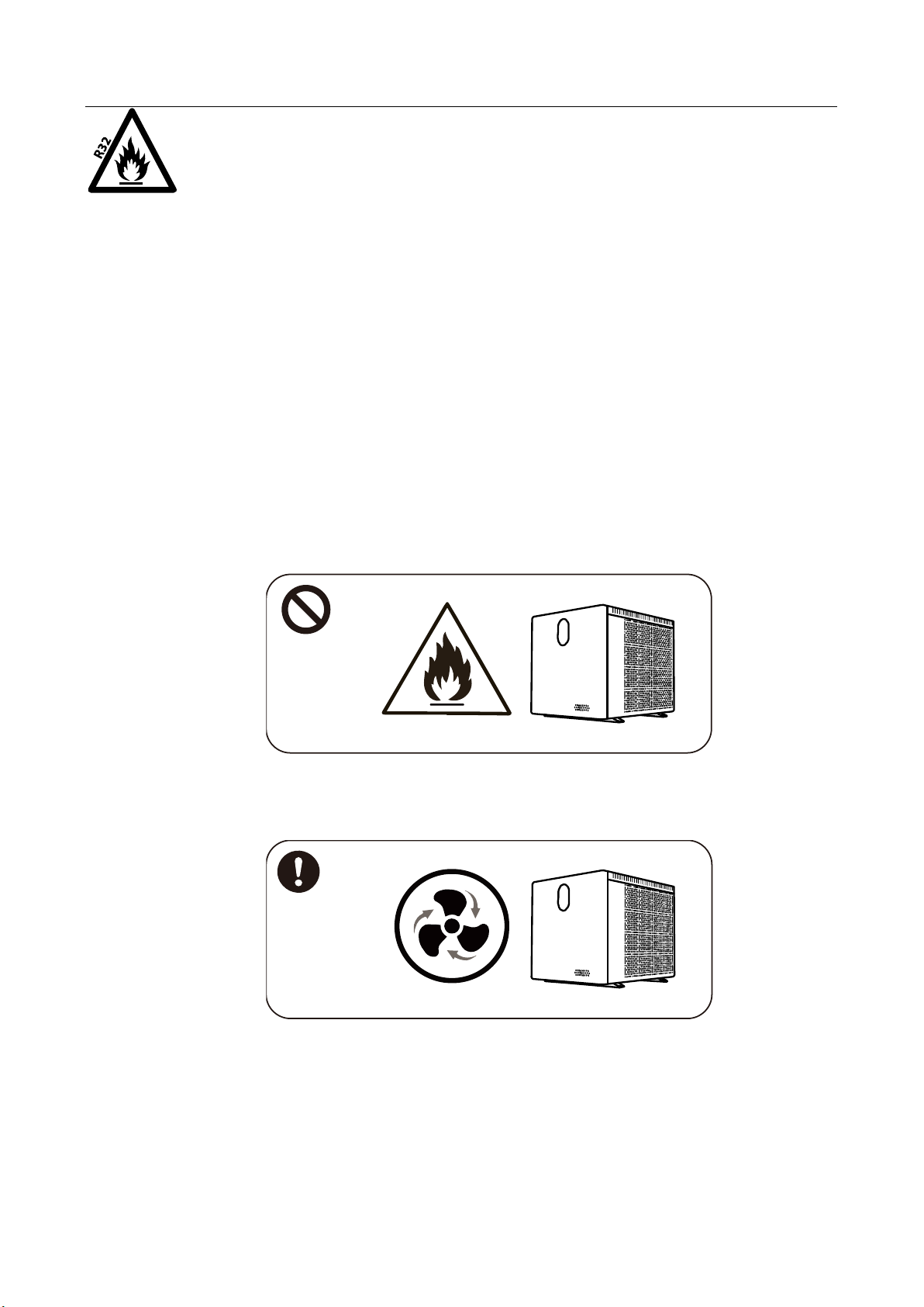
a. This product must be kept away from any source of fire.
b. The installation can’t be in a closed environment or indoors, and must be kept well ventilated.
c. Vacuum completely before welding, field welding is not allowed, welding can only be
performed by professional personnel in professional maintenance center.

Installation and user manual
- 2 -
d. Installation must be stopped if any gas leakage, and the unit must be returned to
professional maintenance center.
3. Transportation & Storage
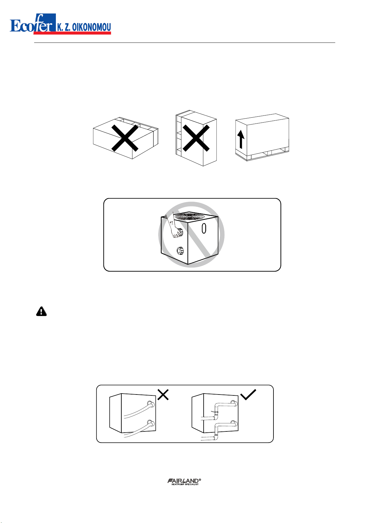
a. Sealing is not allowed during transportation
b. Transporting goods at a constant speed is needed to avoid sudden acceleration or sudden
braking, so as to reduce the collision of goods.
c. The unit must be far away from any source of fire.
d. Storage place must be bright, wide, open and good ventilation, ventilation equipment is
required.
4. Maintenance Notice
a. If maintenance or scrap is required, contact an authorized service center nearby
b. Qualification requirement
All operators who dispose gas must be qualified by valid certification which issued by
professional agency.
c. Please strictly comply with the requirement from manufacturer when maintenance or filling
gas. please refer to the technical service manual.
Installation and user manual
- 3 -
1. General information:
1.1. Contents:
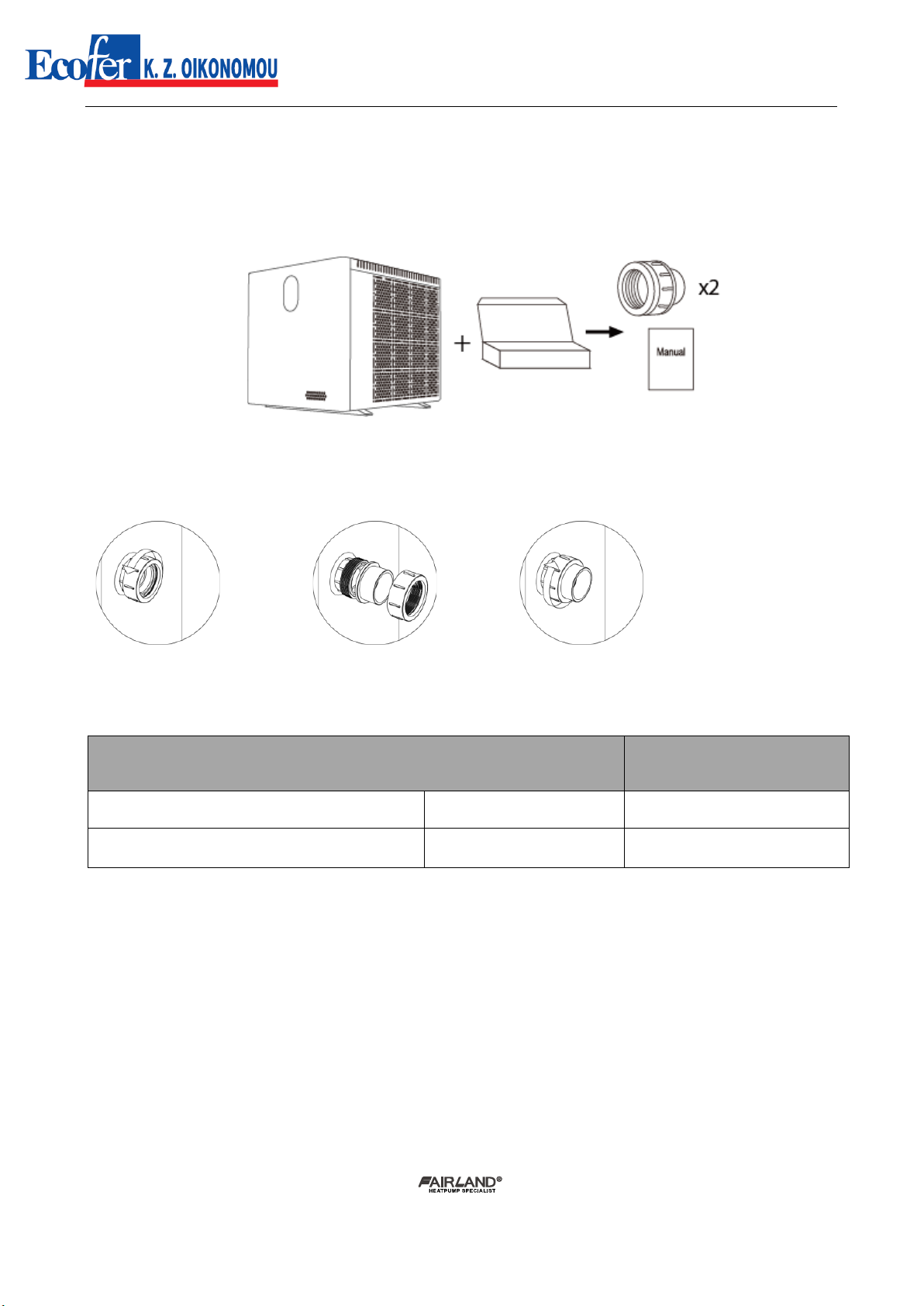
After unpacking, please check if you have all the following components.
NOTICE: Please do not install wrong direction of the water union.
1.2. Operating conditions and range:
ITEMS
RANGE
Operating range
Air temp
-15℃~43℃
Temp. setting
heating
18℃-40℃
The heat pump will have ideal performance in the operation range Air 15
℃~
25
℃
1.3. Advantages of different modes:
The heat pump has three modes: Turbo, Smart and Silence. They have different advantages under
different conditions.
Installation and user manual
- 4 -
Kind reminder:
This heat pump has Power-off memory function. When the power is recovered, the heat pump
will restart automatically.
1. The heat pump can only be used to heat the pool water. It can NEVER be used to heat other
flammable or turbid liquid.
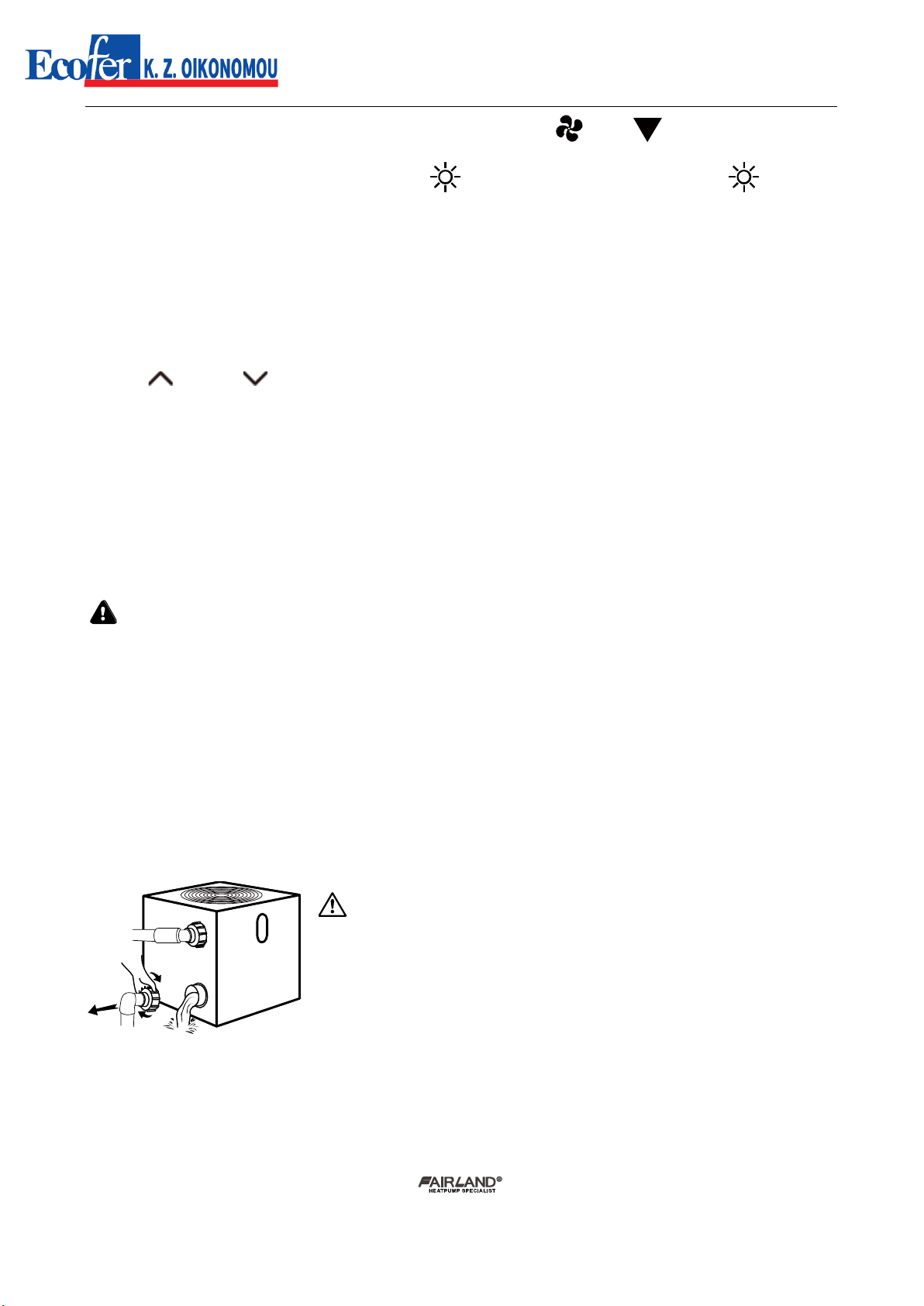
2. Don’t lift the water union when moving the heat pump since the titanium heat exchanger inside
the heat pump will be damaged.
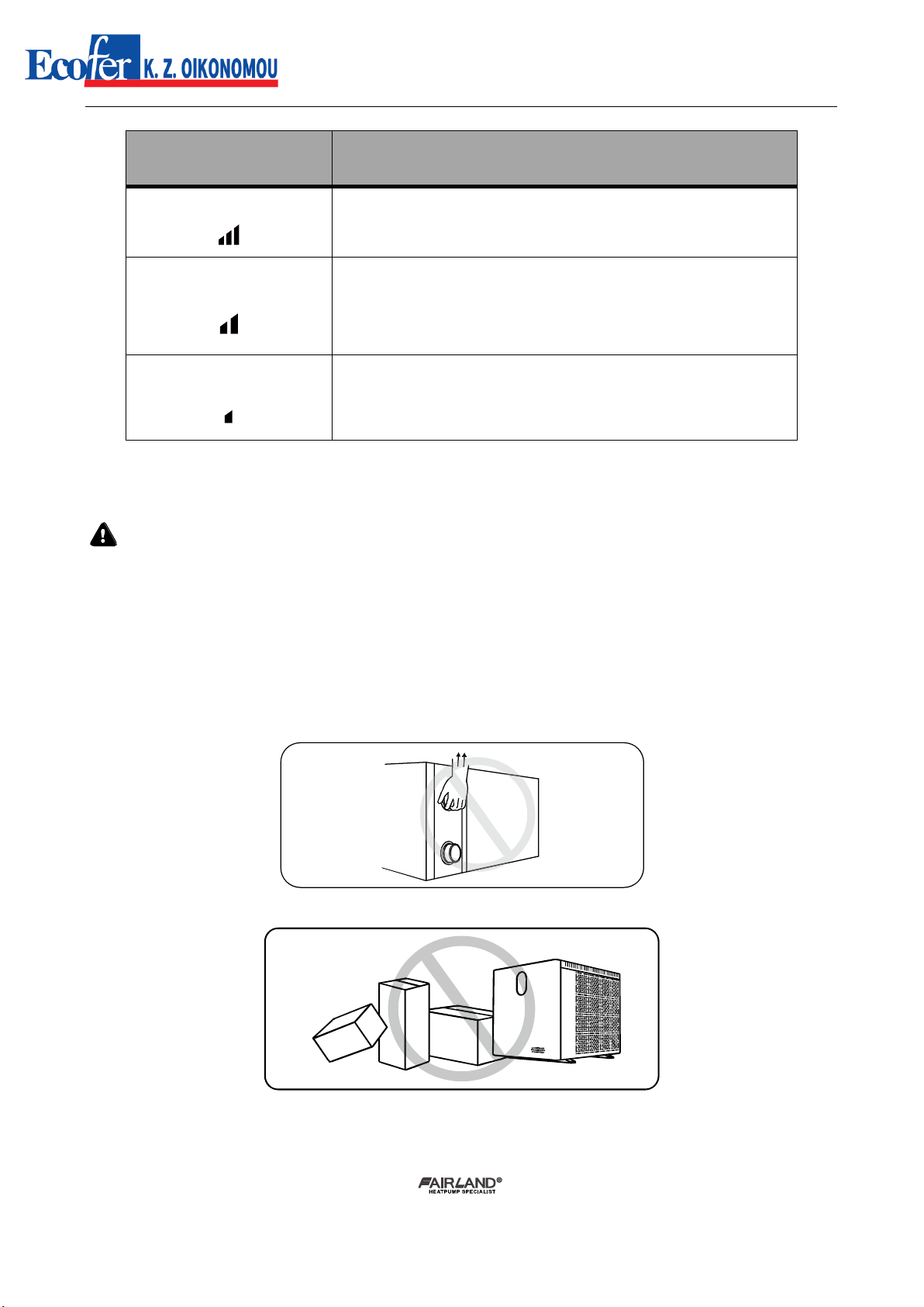
3. Don’t put obstacles before the air inlet and outlet of the heat pump.
4. Don’t put anything into inlet or outlet, or the efficiency of the heat pump will be reduced or
even stopped.
MODE
ADVANTAGES
Turbo mode
Heating capacity: 120%
Fast heating
Smart mode
Heating capacity:100%~20%
Intelligent optimization according to ambient temperature
and water temperature
Energy efficiently saving
Silence mode
Heating capacity: 60%~20%
Use at night

Installation and user manual
- 5 -
5. Don’t use or store combustible gas or liquid such as thinners, paint and fuel to avoid fire.
6. If any abnormal circumstances occurred, e.g.: abnormal noises, smells, smokes and leakage of
electricity, switch off the main power immediately and contact your local dealer. Don’t try
to repair the heat pump by yourselves.
7.. The main power switch should be out of the reach of Children.
8. Please cut off the power in the lightning storm weather.

Installation and user manual
- 6 -
9. Please note that following codes are not failure.
Codes
No water flow
Anti-Freezing Reminder
Out of the operating range
Insufficient water flow or pump
blocked
Power abnormal
2. Operations
2.1. Notice before using
①For longer service life, please ensure water pump is on before heat pump is on, and water
pump is off after heat pump is off.
②Ensure no water leakage on piping system, then unlock screen and power on the heat pump.
2.2. Operation instructions
Installation and user manual
- 7 -
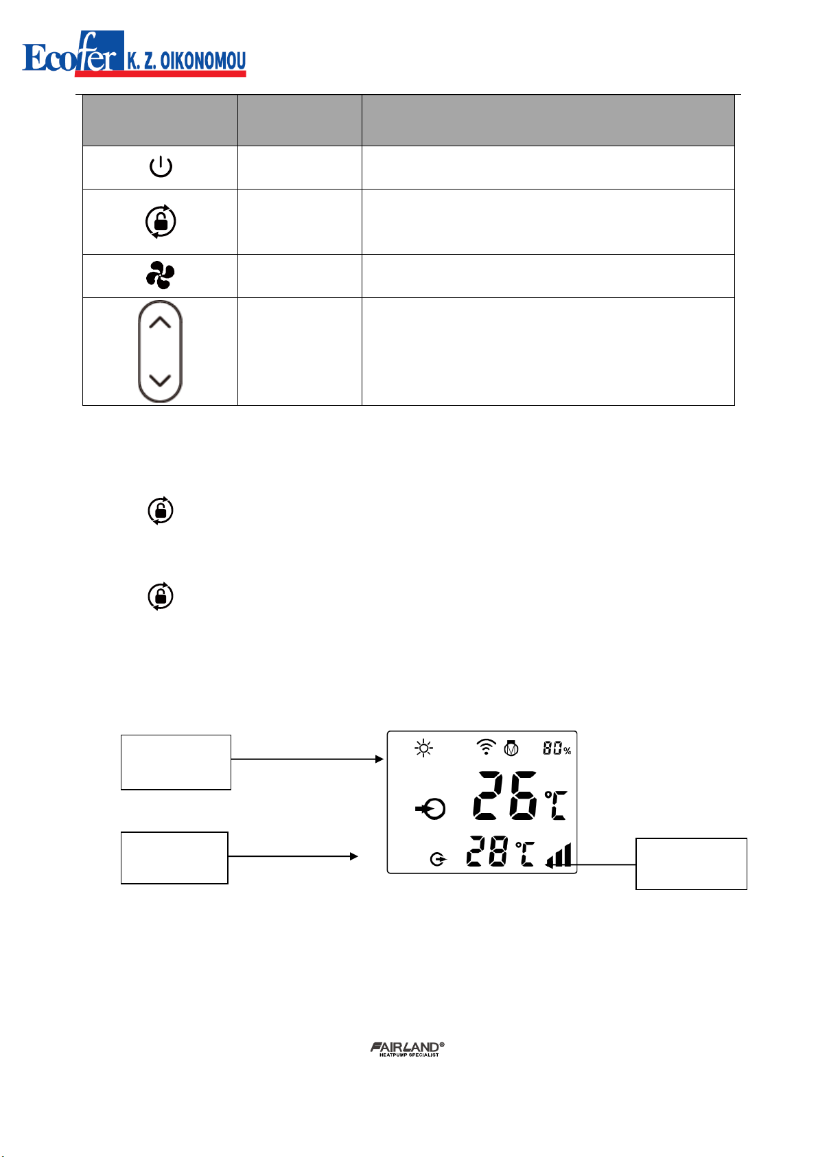
SYMBOL
DESIGNATION
FUNCTION
ON/OFF
1. Power On/Off
2. Wifi setting
Lock/Unlock
Mode Selection
1. Press it for 3 seconds to unlock/lock screen
2. After screen is unlocked, press it to select mode.
Auto (12~40℃) Heating (18~40℃) Cooling (12~30℃)
Speed
Select Turbo/Smart/Silence mode
Up / Down
Adjust set temperature
Note:
①Screen lock:
a. If no operation in 30 seconds, screen will be locked.
b. When HP is off, screen will be dark and “0%” will be displayed.
c. Press for 3 seconds to lock screen and it will be dark
②Screen unlock:
a. Press for 3 seconds to unlock screen and it will be lit up.
b. Only after screen is unlocked, any other buttons can be functioned.
Water inlet
temperature
Water outlet
temperature
Turbo/Smart/
Silence mode

Installation and user manual
- 8 -
Heating
Heating capacity percentage
Wifi connection
Water inlet
Water outlet
1.Power On: Press for 3 seconds to light up screen, then press to power on heat
pump.
2.Adjust Set Temperature: When screen is unlocked, press or to display or adjust the set
temperature.
3. Mode Selection: Press to select mode.
Heating : adjustable temperature range 18~40℃
4. Turbo/Smart/Silence mode selection:
① Smart mode as default will be activated when heat pump is on, and screen shows .
② Press to enter Turbo mode, and screen shows , then press to enter Silence
mode, the screen shows . Press again, the screen shows and return to Smart
mode.
Attention:
a.
When use the Turbo mode, you should select it every time, the machine will not automatically
enter the Turbo mode.
b.
During the Turbo mode, when the machine reaches the set temperature, it will automatically
return to the smart mode.
5. Defrosting
a. Auto Defrosting: When heat pump is defrosting, will be flashing. After defrosting,
will stop flashing.
Installation and user manual
- 9 -
b. Compulsory Defrosting: When heat pump is heating, press and together for 5
seconds to start compulsory defrosting, and will be flashing. After defrosting, will stop
flashing.
(Note: Compulsory defrosting intervals should be more than 30 minutes and the compressor
should run for more than 10 minutes.)
6.Temperature display conversion between ℃and ℉:
Press " " and " " together for 5 seconds to switch between ℃and ℉.
7. Wifi setting
Please kindly check the last page.
2.3. Daily maintenance and winterizing
2.3.1. Daily Maintenance
Please don’t forget to cut off power supply of the heat pump
➢Please clean the evaporator with household detergents or clean water, NEVER use gasoline,
thinners or any similar fuel.
➢Check bolts, cables and connections regularly.
2.3.2. Winterizing
In winter season when you don’t swim, please cut off power supply and drain water out of
the heat pump. When using the heat pump under 2℃, make sure there is always water flow.
Important:
Unscrew the water union of inlet pipe
to let the water flow out.
When the water in machine freezes in
winter season, the titanium heat
exchanger may be damaged.

Installation and user manual
- 10 -
3. Technical specification
Model
IXCR26V
IXCR36V
IXCR46V
IXCR56V
IXCR66V
IXCR80V
IXCR80VT
IXCR110VT
Advised pool volume (m3)
20~40
25~50
30~60
40~75
50~100
65~120
65~120
90~160
Working air temp (℃)
-15οC ~ +43οC
Performance Condition: Air 28°C, Water 26°C, Humidity 80%
Heating capacity (kW) in SMART
mode
9,3
12,0
15,4
19,0
24,3
29,0
29,0
37,0
Heating capacity (kW) in TURBO mode
11,0
14,3
18,5
22,8
28,5
34,0
34,0
42,0
C.O.P in SMART mode
8,3
8,3
8,5
8,1
8,5
8,0
8,0
7,9
C.O.P
16.3~7.5
16.5~7.4
17.0~7.1
16.9~6.9
16.2~7.5
17.2~6.9
17.2~6.9
16.9~7.0
C.O.P at 50% capacity
12,2
12,5
12,8
12,7
12,3
12,2
12,2
12,1
Performance Condition: Air 15°C, Water 26°C, Humidity 70%
Heating capacity (kW) in SMART
mode
6,3
7,5
10,0
12,0
15,0
18,5
18,5
24,5
Heating capacity (kW) in TURBO mode
7,5
9,0
12,0
14,5
18,0
22,0
22,0
28,5
C.O.P in SMART mode
5,1
5,1
5,0
5,0
5,1
5,5
5,5
5,3
C.O.P
7.2~4.5
7.5~4.6
8.0~4.6
7.6~4.5
7.5~4.9
8.0~5.0
8.0~5.0
7.9~4.8
C.O.P at 50% capacity
6,6
6,7
6,9
7,0
6,5
7,0
7,0
6,9
Performance Condition: Air 32°C, Water 28°C, Humidity 80%
Cooling capacity (kW)
4,95
6,4
7,8
9,0
13,2
15,4
15,4
18
Rated input power(kW) at air 15°C
0.17~1.66
0.21~1.95
0.26~2.51
0.33~3.08
0.42~3.67
0.46~4.4
0.46~4.4
0.60~5.94
Rated input current(A) at air 15°C
0.74~7.21
0.91~8.48
1.14~10.9
1.43~13.4
1.82~15.9
2.01~19.1
0.66~6.35
0.87~8.57
Τροφοδοσία / Power supply
230V/1 Ph/50Hz
400V/3 Ph/50Hz
Advised water flux (m³/h)
2~4
3~4
4~6
6.5~8.5
8~10
10~12
10~12
12~18
Sound pressure 1m dB(A)
38.8~46.5
38.8~47.9
42.2~48.6
43.1~52.1
41.0~52.9
43.6~53.8
43.6~53.8
42.8~54.0
Sound pressure of 50% capacity at 1m
dB(A)
39,0
41,9
44,3
45,2
45,3
46,7
46,7
46,9
Sound pressure 10m dB(A)
18.8~26.5
18.8~27.9
22.2~28.6
23.1~32.1
21.0~32.9
23.6~33.8
23.6~33.8
22.8~34.0
Exchanger
Spiral titanium tube in PVC
Casing
Aluminum
Water pipe in-out Spec (mm)
50
Net Dimension LxWxH (mm)
710x753x
693
710x753x
693
710x775x
693
710x775x
693
710x775x
743
729x955x
943
729x955x
943
845x955x
943
Net Weight (kg)
61
66
71
77
95
108
117
141
Refrigerant R32 (gr)
550
700
1000
1200
2000
2300
2300
3200
CO2 equivalent (tonnes)
0,371
0,473
0,675
0,810
1,350
1,553
1,553
2,160
GWP
675
1. The values indicated are valid under ideal conditions: Pool covered with an isothermal cover, filtration system running at least 15 hours a day.
2. Related parameters are subject to adjustment periodically for technical improvement without further notice. For details please refer to
nameplate.
Installation and user manual
- 11 -
4. Transportation
4.1. When storing or moving the heat pump, the heat pump should be at the upright
position.
4.2. When moving the heat pump, do not lift the water union since the titanium heat exchanger
inside the heat pump will be damaged.
5. Installation and maintenance
The heat pump must be installed by a professional team. The users are not qualified to install
by themselves, otherwise the heat pump might be damaged and risky for users’ safety.
5.1. Notice before installation:
5.1.1. The inlet and outlet water unions can’t bear the weight of soft pipes. The heat pump must
be connected with hard pipes!
5.1.2.In order to guarantee the heating efficiency, the water pipe length should be ≤10m
between the pool and the heat pump.
Installation and user manual
- 12 -
5.2. Installation instruction
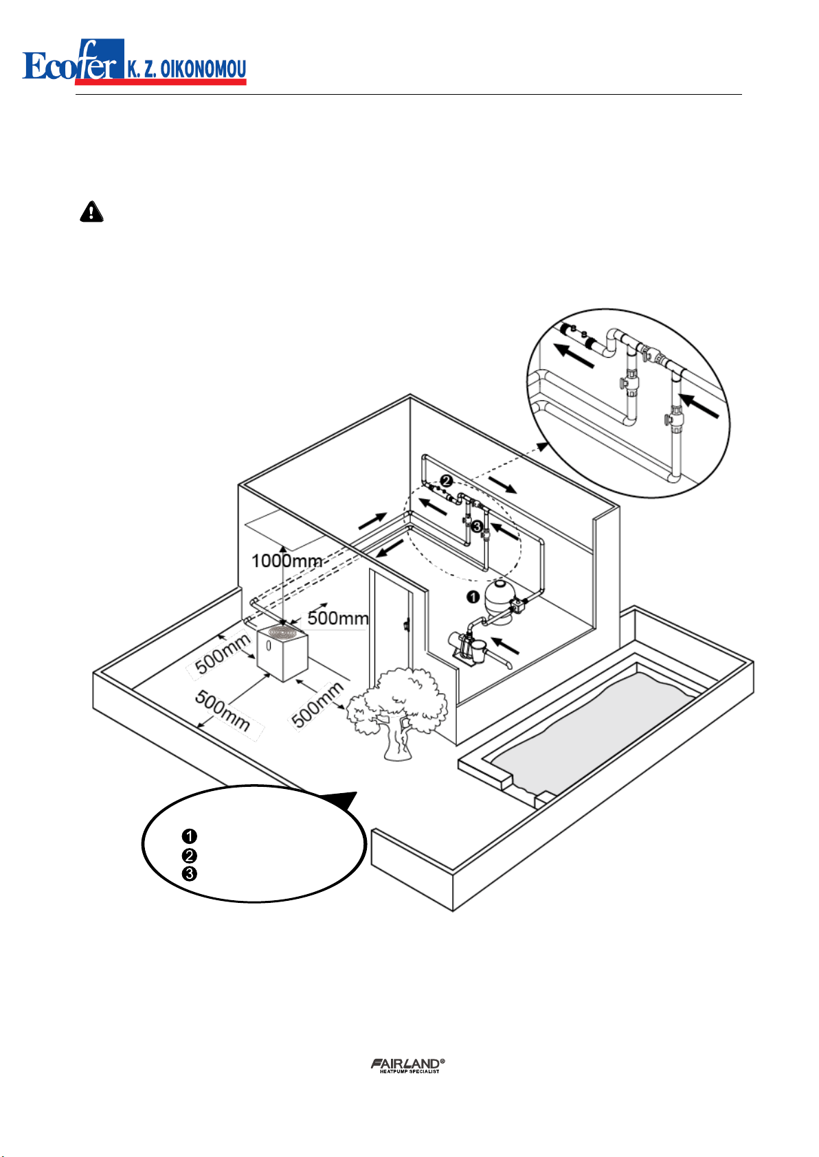
5.2.1. Location and size
To avoid air recirculation, the heat pump should be installed in a place with good ventilation
or should reserve sufficient space for installation and maintenance. Please refer to the schema
below:
* MINIMUM DISTANCE
Filter
Water processor
Water switch

Installation and user manual
- 13 -
※
Above data is subject to modification without notice.
5.2.2. Heat pump installation.
➢The frame must be fixed by bolts (M10) to concrete foundation or brackets. The concrete
foundation must be solid; the bracket must be strong enough and anti-rust treated;
➢The heat pump needs a water pump (Supplied by the user). The recommended pump
specification-flux: refer to Technical Parameter, Max. lift ≥10m
➢When the heat pump is running, there will be condensation water discharged from the bottom,
please pay attention to it. Please insert the drainage tube(accessory) into the hole and clip it
well, then connect a pipe to drain off the condensation water.
5.2.3. Wiring & protecting devices and cable specification
➢Connect to appropriate power supply, the voltage should comply with the rated voltage of the
products.
➢Well earth the heat pump.
UNIT=MM
A
B
C
D
E
F
G
H
MODEL
IXR26V
685
441
753
710
688
300
75.5
693
IXR36V
685
441
753
710
688
280
75.5
693
IXR46V
685
463
775
710
688
350
75.5
693
IXR56V
685
463
775
710
688
390
75.5
693
IXR66V
685
463
775
710
688
460
75.5
743
IXR80V
703
555
955
729
707
640
75.5
943
IXR80VT
703
555
955
729
707
640
75.5
943
IXR110VT
819
555
955
845
823
650
75.5
943

Installation and user manual
- 14 -
➢Wiring must be connected by a professional technician according to the circuit diagram.
➢Set breaker or fuse according to the local code (leakage operating current ≤ 30mA).
➢The layout of power cable and signal cable should be orderly and not affecting each other.
1. Wiring diagram
NOTE:
Must be hard wired, no plug allowed
For your safe use in winter, it’s strongly recommended to equip heating priority function.
For the detailed wiring diagram, please refer to Appendix 1.
2.Options for protecting devices and cable specification
MODEL
IXR26
IXR36
IXR46
IXR56
IXR66
IXR80
IXR80T
IXR110T
Breaker
Rated Current A
12.0
15.0
19.0
22.5
24.5
28.5
11.3
15.0
Rated Residual Action Current mA
30
30
30
30
30
30
30
30
Fuse A
12.0
15.0
19.0
22.5
24.5
28.5
11.3
15.0
Power Cord(mm2)
3×2.5
3×2.5
3×4
3×4
3×6
3×6
5×2.5
5×2.5
Signal cable(mm2)
3×0.5
3×0.5
3×0.5
3×0.5
3×0.5
3×0.5
3×0.5
3×0.5
A. For power supply: 230V 50Hz
Distribution Box(Customer prepare)
Power Cord
Swimming Pool Heat Pump Wiring Board
Power Supply
400V 50Hz
Breaker
Distribution Box(Customer prepare)
Power Cord
Swimming Pool Heat Pump Wiring Board
Power Supply
230V 50Hz
Breaker
B. For power supply: 400V 50Hz
Earthing
Earthing
Fuse
Fuse

Installation and user manual
- 15 -
NOTE: The above data is adapted to power cord ≤ 10m .If power cord is
>
10m, wire diameter must be
increased. The signal cable can be extended to 50m at most.
5.3. Trial after installation
Please check all the wirings carefully before turning on the heat pump.
5.3.1.Inspection before use
➢Check installation of the whole heat pump and the pipe connections according to the pipe
connecting drawing;
➢Check the electric wiring according to the electrical wiring diagram and earthing connection;
➢Make sure that the main power is well connected;
➢Check if there is any obstacle in front of the air inlet and outlet of the heat pump
5.3.2.Trial
➢The user is advised to start the water pump before the heat pump, and turn off the heat pump
before the water pump for long life circle.
➢The user should start the water pump, and check for any leakage of water; Power on and press
the ON/OFF button of the heat pump, and set desired temperature in the
thermostat.
➢In order to protect the heat pump, the heat pump is equipped with start delay
function. When starting the heat pump, the fan will start to run in 3 minutes, in another
30 seconds, the compressor will start to run.
➢After pool heat pump starts up, check for any abnormal noise from the heat pump.
➢Check the temperature setting
5.4. Maintenance and winterizing
5.4.1 Maintenance
The maintenance should be carried out once per year by qualified professional technician.
➢Cut off power supply of the
heat pump before cleaning,
examination and repairing .
Do not touch the electronic
components until the LED
indication lights on PCB turn off.
➢Please clean the evaporator with household
detergents or clean water, NEVER use gasoline, thinners or any similar fuel.
➢Check bolts, cables and connections regularly.

Installation and user manual
- 16 -
5.4.2 Winterizing
In winter season when you don’t swim, please cut off power supply and drain water out of the
heat pump. When using the heat pump under 2℃, make sure there is always water flow.
6 . Trouble shooting for common faults
FAILURE
REASON
SOLUTION
Heat pump doesn’t run
No power
Wait until the power recovers
Power switch is off
Switch on the power
Fuse burned
Check and change the fuse
The breaker is off
Check and turn on the breaker
Fan running but with
insufficient heating
evaporator blocked
Remove the obstacles
Air outlet blocked
Remove the obstacles
3 minutes start delay
Wait patiently
Display normal, but no
heating
Set temp. too low
Set proper heating temp.
3 minutes start delay
Wait patiently
If above solutions don’t work, please contact your installer with detailed information and your model number. Don’t
try to repair it yourself.
ATTENTION!Please don’t try to repair the heat pump by yourself to avoid any risk.
Important:
Unscrew the water union of inlet pipe to let the water
flow out.
When the water in machine freezes in winter season,
the titanium heat exchanger may be damaged.
Installation and user manual
- 17 -
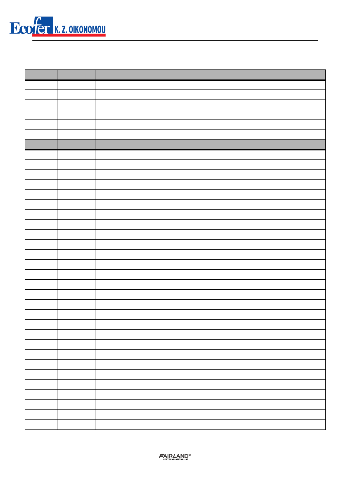
7. Failure code
NO.
DISPLAY
NOT FAILURE DESCRIPTION
1
E3
No water protection
2
E5
Power supply excesses operation range
3
E6
Excessive temp difference between inlet and outlet water(Insufficient water flow protection)
4
Eb
Ambient temperature too high or too low protection
5
Ed
Anti-freezing reminder
NO.
DISPLAY
FAILURE DESCRIPTION
1
E1
High pressure protection
2
E2
Low pressure protection
3
E4
3 phase sequence protection (three phase only)
4
E7
Water outlet temp too high or too low protection
5
E8
High exhaust temp protection
6
EA
Evaporator overheat protection (only at cooling mode)
7
P0
Controller communication failure
8
P1
Water inlet temp sensor failure
9
P2
Water outlet temp sensor failure
10
P3
Gas exhaust temp sensor failure
11
P4
Evaporator coil pipe temp sensor failure
12
P5
Gas return temp sensor failure
13
P6
Cooling coil pipe temp sensor failure
14
P7
Ambient temp sensor failure
15
P8
Cooling plate sensor failure
16
P9
Current sensor failure
17
PA
Restart memory failure
18
F1
Compressor drive module failure
19
F2
PFC module failure
20
F3
Compressor start failure
21
F4
Compressor running failure
22
F5
Inverter board over current protection
23
F6
Inverter board overheat protection
24
F7
Current protection
25
F8
Cooling plate overheat protection
26
F9
Fan motor failure
27
Fb
Power filter plate No-power protection
28
FA
PFC module over current protection
Table of contents
Other ECOFER Heat Pump manuals

Popular Heat Pump manuals by other brands

Action Clima
Action Clima FCS Series Installation use and service manual

Nortek
Nortek RQ7RE installation instructions

ClimateMaster
ClimateMaster TMW Series Installation operation & maintenance

Daikin
Daikin RZQG71~140L7V1B Service manual

Trane
Trane Axiom VSHE024 Operating and maintenance

Nibe
Nibe F2050 user manual


Trane
Trane 4WCC4024E1000A Installation and operation manual

Dimplex
Dimplex LAS 10MT Installation and operating instructions

Zodiac
Zodiac Z900 TD20 Instructions for installation and use

CTC Union
CTC Union EcoPart 400 400V 3N Installation and maintenance manual

Heat Controller
Heat Controller AS-W303DPZ0 Service manual

Multistack
Multistack AirStack VersaTemp ARA 020X Product data