EcoInnovation PowerSpout TRG 28 User manual
© 2018 EcoInnovation Ltd (NZ) Page 1
PowerSpout Turbine Installation Manual
PowerSpout TRG

PowerSpout TRG installation 2018
Last revised July 2018 © 2018 EcoInnovation Ltd (NZ) Page 2
PowerSpout Contact details
Web: www.powerspout.com
PowerSpout is a product proudly designed and manufactured by:
EcoInnovation Ltd
671 Kent Road
New Plymouth R.D.1
New Zealand 4371
Web: www.ecoinnovation.co.nz
If you need to contact EcoInnovation by phone then email first via our web site and
check the local time in NZ if calling from overseas. Business hours are 9:00am to
5:00pm (NZ time) weekdays only. EcoInnovation is closed for up to 3 weeks over the
Christmas break.
Disclaimer
UNLESS SPECIFICALLY AGREED TO IN WRITING, ECOINNOVATION LIMITED:
(a) MAKES NO WARRANTY AS TO THE ACCURACY, SUFFICIENCY OR SUITABILITY
OF ANY TECHNICAL OR OTHER INFORMATION PROVIDED IN ITS MANUAL OR
OTHER DOCUMENTATION.
(b) ASSUMES NO RESPONSIBILITY OR LIABILITY FOR LOSS OR DAMAGE, WHETHER
DIRECT, INDIRECT, CONSEQUENTIAL OR INCIDENTAL, WHICH MIGHT ARISE OUT OF
THE USE OF SUCH INFORMATION. THE USE OF ANY SUCH INFORMATION WILL BE
ENTIRELY AT THE USER’S RISK.
Notice of Copyright
Copyright © 2018 All rights reserved
Notice of Trademark
PowerSpout –is a USA registered Trademark
Notice of Company Registration
EcoInnovation –is a NZ Registered Limited Company
Revisions history
1.0 Edited by H.P. May 2018

PowerSpout TRG installation 2018
Last revised July 2018 © 2018 EcoInnovation Ltd (NZ) Page 3
CONTENTS
1. Introduction...................................................................................................................5
1.1. This manual and other information sources..............................................................5
1.1.1. When planning your system...........................................................................5
1.1.2. When installing an off-grid system..................................................................5
1.1.3. When operating and maintaining your TRG turbine........................................5
1.2. Product scope and specification...............................................................................6
1.2.1. Scope of application.......................................................................................6
1.2.2. CE and FCC Declaration................................................................................6
1.2.3. Standards and certification.............................................................................6
1.2.4. Turbine serial numbers...................................................................................7
1.3. Safety.......................................................................................................................7
1.3.1. Electrical hazards...........................................................................................8
1.3.2. Lead Acid battery safety.................................................................................8
1.3.3. Mechanical hazards .......................................................................................9
1.3.4. Water hazards................................................................................................9
1.3.5. Installation and maintenance hazards ............................................................9
2. Your TRG turbine........................................................................................................11
2.1. Parts, functions and assembly................................................................................11
2.1.1. Turbine protective casing .............................................................................12
2.1.2. Valves..........................................................................................................12
2.1.3. Pressure Gauge...........................................................................................13
2.1.4. Camlock fittings............................................................................................14
2.1.5. Jet sleeve and cap .......................................................................................14
2.1.6. Jet inserts.....................................................................................................15
2.1.7. Turbine runner/rotor mounting......................................................................17
2.1.8. Shaft and bearing block installation..............................................................18
2.1.9. Changing the bearings.................................................................................19
2.1.10. Greasing the bearings.................................................................................20
2.1.11. The stator....................................................................................................22
2.1.12. Rectifier.......................................................................................................24
2.1.13. The magnet rotor.........................................................................................24
2.2. Turbine installation .................................................................................................26
2.2.1. Mounting......................................................................................................26
2.3. Commissioning procedures....................................................................................29
2.3.1. Electrical checks with covers off - before install............................................29
2.3.2. Turbine RPM and voltage.............................................................................29
2.3.3. Commissioning the turbine...........................................................................30
2.3.4. Commissioning (models TRG14, 28 or 56) connected directly to battery......30
2.3.5. Commissioning (models TRG40, 80 or 200) connected to MPPT or GTI......31
2.3.6. All turbine models - final commissioning checks...........................................34
2.3.7. Labeling requirements..................................................................................35
2.3.8. Installation details.........................................................................................36
2.4. Turbine operation...................................................................................................37
2.4.1. Monitoring ....................................................................................................37
2.4.2. Intake cleaning.............................................................................................37
2.4.3. Operation of control valves...........................................................................37
2.4.4. Optimisation of jet size .................................................................................38
2.4.5. Thermal Checks...........................................................................................40
2.4.6. Maintenance.................................................................................................40
2.4.7. Spare parts ..................................................................................................41
2.4.8. Troubleshooting ...........................................................................................42

PowerSpout TRG installation 2018
Last revised July 2018 © 2018 EcoInnovation Ltd (NZ) Page 4
2.4.9. Making the most of your pressure gauge......................................................43
2.4.10. Turbine case flooding..................................................................................43
3. Reference section.......................................................................................................44
3.1. Units and conversions............................................................................................44
3.2. Common versions of PowerSpout TRG..................................................................44
3.3. TRG Specifications.................................................................................................45

PowerSpout TRG installation 2018
Last revised July 2018 © 2018 EcoInnovation Ltd (NZ) Page 5
1. Introduction
1.1. This manual and other information sources
This document is part of the product. It has 3 sections.
1. Scope, certification, identification and safety (this introduction).
2. The parts of the turbine, how to assemble, install and operate it.
3. Reference material.
We offer a wide range of other free documents in pdf format, and some videos. All relevant
manuals are considered to be part of the product.
Have a look at our Document Index for further reading and videos on specific topics relevant
to your situation. Here is a brief summary of documents that will answer your questions:
1.1.1. When planning your system
Site assessment guide
Intake guide and Coanda intake guide
Pipe selection guide
Manifold guide
Hydro design and calculator manual
You can estimate your site's generation potential and even design the whole system
painlessly using our online Advanced Calculator Tool. To get the best out of it please read
the Hydro design and calculator manual first.
1.1.2. When installing an off-grid system
Power conversion equipment guide
Battery guide
Charge controller guide
System wiring guide
Powershed design guide
Diversion load guide
1.1.3. When operating and maintaining your TRG turbine
Your log book
Bearing care guide
Our worldwide network of dealers can also help you with system design and choosing the
best equipment for your situation.

PowerSpout TRG installation 2018
Last revised July 2018 © 2018 EcoInnovation Ltd (NZ) Page 6
1.2. Product scope and specification
1.2.1. Scope of application
PowerSpout turbines convert waterpower into electricity. The product is custom-built to
match your specific site conditions and requirements. Therefore customers or dealers must
provide us with site data (head, flow, pipe dimensions, cable dimensions and type of inverter
or controller) with each order.
PowerSpout turbines will not be supplied to customers who propose to use the electrical
output of the turbine to pump water that in turn supplies the turbine itself. We refuse to
support applications that have no external source of energy. Demonstration units operating
from independently pumped sources of water will be supported where the customer
understands that no net energy will be generated.
The installer must:
Check for any transit damage to the product prior to installing it. If damaged it must not
be installed. If the turbine is being freighted on to the end client then you must check it
prior to this next freight leg.
Connect equipment in compliance with the relevant national standards.
Read and comply with this installation manual.
Limits of head and flow, with estimated power shown as contours (dotted)
See the reference section 3 for full specifications of the TRG turbine.
1.2.2. CE and FCC Declaration
Refer to our compliance declaration documentation and EMC test reports.
PowerSpouts products are CE, FCC and C-tick compliant.
PowerSpout dealers may request to see the Compliance Folder if required by authorities.
1.2.3. Standards and certification
All PowerSpout turbines have been evaluated against major international standards.
Refer to compliance declaration documentation and EMC test reports.

PowerSpout TRG installation 2018
Last revised July 2018 © 2018 EcoInnovation Ltd (NZ) Page 7
1.2.4. Turbine serial numbers
All turbines have identification plates and serial numbers.
For example:
You might see 100-7S-2P-S HP F 3061 A as the serial number.
This means you have a 100 series stator, connected 7 Series and 2 Parallel fingers per
phase, High Power rotor upgrade, Filter installed for conducted emission compliance, invoice
number 3061 and other identical units were supplied at the same time labelled A, B, C, D
etc.
If you ever need to query an installation or order spares for a product take a picture of the
identification plate and forward it with your query. The generator code is also engraved on
the back of the PMA stator.
1.3. Safety
This section addresses safety concerns as required by international standards.
If you are not technically competent, experienced and qualified you should not install this
equipment alone and should engage the services of a suitably trained professional.
Electrical equipment can be installed or operated in such a manner that hazardous
conditions can occur; compliance with this manual does not by itself assure a 100% safe
installation. If the equipment is properly selected and correctly installed and operated
according to this manual, then any such hazards will be minimized.
The installation shall be carried out by installers with recognized and approved qualifications,
and experience relating to general electrical installations and micro-generators.
The following safety warning signs are used throughout this manual.
Caution
Risk of electric shock that could result in personal injury or loss of life
Caution
Cautions identify condition or practices that could result in damage to
equipment or personal injury, other than by electric shock.

PowerSpout TRG installation 2018
Last revised July 2018 © 2018 EcoInnovation Ltd (NZ) Page 8
1.3.1. Electrical hazards
Protect the supply cable in conduit as per local wiring rules, ensure wiring, insulation,
conductors and routing of all wires of the equipment is suitable for the electrical, mechanical,
thermal and environmental conditions of use. Finger-tighten all cable glands to secure the
supply cable.
Shock hazards
DC voltage from turbines is volatile, and can reach three times higher than the
rated operating voltage under some conditions. Controllers and inverters
contain capacitors that can store and deliver lethal voltages through wiring.
All exposed wiring and connections must be inaccessible. Covers may only be removed
when the turbine is stopped and a suitable time has elapsed for capacitor discharge.
This Class I equipment must be suitably earthed/grounded (turbine bulkhead).
Do not connect a DC pole of the turbine to earth - unless local rules require it.
Provide a suitable DC-rated disconnection device close to the turbine that is clearly labelled.
(A 2-pole DC breaker is the good recommended solution.) In general, hard wiring is
required. However “MC4” type waterproof connectors may be used provided they are never
opened under load. (Turbine must be stopped before unplugging.)
Fire hazards
Wiring must be adequately sized to carry short-circuit current from the turbine (listed on the
identification plate).
Loose connections can cause electric arcs to occur that could ignite flammable materials.
Tighten all electrical connections inside the turbine very securely during installation.
Assess fire risk of the installation site, and if high implement extra fire precautions as
appropriate. In environments where combustible materials are present the turbine must be
mounted in a concrete or metal enclosure. If your hydro turbine is situated in a very dry
bush/forest environment where the fire risk is high, then a ground-fault protection device
(GFPD) should also be installed.
1.3.2. Lead Acid battery safety
Batteries store energy in chemical form and can release this as electricity very
quickly if there is a short circuit. A short circuit can convert a steel ruler or
spanner to molten metal spray and cause significant personal injury.
Batteries contain explosive gasses that can be ignited by sparks to create an explosion
that scatters sharp debris and acid.
Protection from falling objects is required. Metal objects falling into contact with the
battery terminals could cause a fire.
Never leave a cable loose at one end whilst connected to a battery at the other. It can all
too easy flop against another terminal and strike an arc.
Never disconnect cables from a battery that is being charged/discharged as this creates
a spark.
Batteries give off hydrogen and oxygen gas during charging in the correct proportions
for an explosion. Ventilation of the enclosure is required.
Terminals should be checked annually for tightness and clean if any corrosion is
observed.

PowerSpout TRG installation 2018
Last revised July 2018 © 2018 EcoInnovation Ltd (NZ) Page 9
Batteries are not maintenance free. All batteries need to be checked periodically for
individual voltage and flooded batteries also need to be checked with a hydrometer.
"Flooded Lead Acid" (FLA) batteries need to be checked for electrolyte level regularly
and topped up. If this is not done they will be ruined and the risk of explosion increases.
It is important to plan the accommodation of the batteries so that topping up with water is
easy to do. Batteries will use more water as they age. Consider fitting battery
recombination vents to significantly
reduce the need to top up with water.
Watering intervals can be as long as 12
months with such vents fitted.
Batteries are not for anyone to touch.
Sufficient security is required to
prevent a child or unknowing adult
from tampering with them.
Not everybody understands batteries.
There are recommended safety signs
that must be displayed above your
battery bank warning people of the
possible hazards.
Batteries are heavy and need a solid
flat supporting surface. Good access
for installation and replacement to
avoid lifting injuries is required.
You should always take care when working with batteries. Burns, acid splashes and even
electric shocks can occur. If you do not have sufficient skill and/or experience to install and
care for this equipment you should engage a renewable energy professional to do it for you.
1.3.3. Mechanical hazards
Once the turbine has been commissioned, the top fairing needs to be fastened
in place with the fixings provided.
The turbine installer should ensure that the turbine is mounted such that
children cannot reach up under the turbine and be able to touch the spinning rotors.
1.3.4. Water hazards
Ensure you install pipe with the correct pressure rating. Allow for pressure
surges in operation that result from closure of valves.
Legislation covering pressurised pipes applies in most countries for pipe pressures over 10
bar. The PowerSpout TRG runs at less than 4 bar.Generally there is little risk at less than
10 bar pressure. The biggest risk is insecurely fastened pipe joiners that blow off, with the
free end of the pipe hitting people. Securing the pipe at regular intervals, particularly near the
joins, and checking all joiners are tight will eliminate such risks.
1.3.5. Installation and maintenance hazards
Penstocks (pipelines) are often routed through steep locations with various
hazards including danger of falling from heights, or rocks etc falling from
above. Take care to prepare suitable access to the site and install safety
ropes, steps, etc.
PowerSpout TRG installation 2018
Last revised July 2018 © 2018 EcoInnovation Ltd (NZ) Page 10
Polyethylene pipe can be hazardous when uncoiling. The pipe behaves like a spring that
can recoil with surprising violence and cause injury. Take care when releasing the binding
from coils of pipe. Take care when straightening pipes that they do not spring back and hit
somebody. Give the pipe time to change shape. Warmer temperatures speed this process
up.
Commissioning hazards and safe practices
Securely fix the turbine base prior to operation.
Do not intentionally run turbine unloaded (for other than short duration VOC testing).
Do not run turbine at a head significantly above the nameplate rating.
In a turbine runaway situation turn off the water supply by closing the water supply
valve(s).
Check for excessive noise.
Complete turbine testing and commissioning and ensure that all protective
fairing/enclosures are in position after commissioning and prior to client hand over.
Comply with signage requirements as listed in relevant national standards.
Complete all documentation as required in this manual and local wiring rules.
Make relevant notes in the manuals that will be of assistance to future service personal.
Train the end owner/user of the turbine in routine care, safe handling and maintenance
of the hydro system.
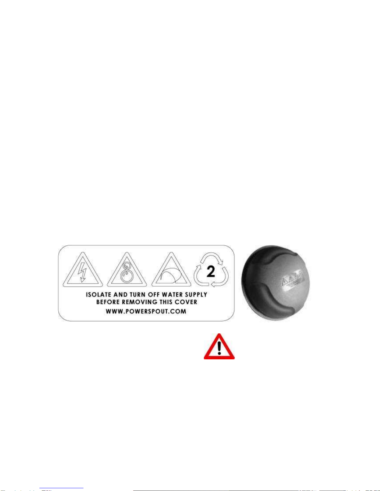
Fairing safety warnings
The fairing on your PowerSpout turbine forms part of an electrical enclosure and carries the
following warning signs. There are both rotational and electrical hazards present. Turbines
must be turned off at the valve and the electrical breaker turned off prior to removing this
cover.
Electrical hazard
Rotating machinery hazard
Made in New Zealand identification
Recycling identification
PowerSpout TRG installation 2018
Last revised July 2018 © 2018 EcoInnovation Ltd (NZ) Page 11
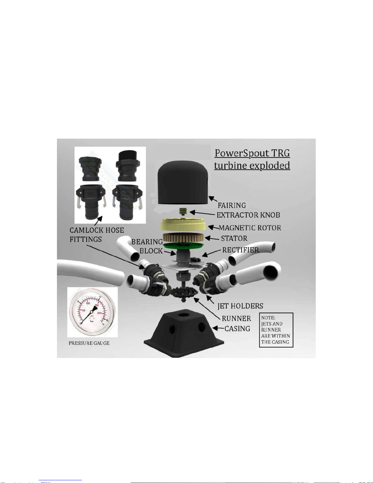
2. Your TRG turbine
2.1. Parts, functions and assembly
Congratulations on your choice of a PowerSpout turbine. This ingenious little device will give
you years of trouble free generation, avoiding the need for expensive generators or power
bills. Not only does the PowerSpout give you renewable energy, it is also made of
predominately recycled materials, making it one of the most eco-friendly micro-hydro
generators available on the global market.
This section is a guide to the parts of the turbine and what is supplied with it. If you
disassemble your turbine, take careful note of the positions of parts including any washers.
Take photographs to remind you of the details.
Your turbine will probably arrive assembled other than jets and valves, but we recommend
that you remove the magnetic rotor whilst greasing for the first time (shaft spinning). You
may need to remove the stator so as to connect wiring to the rectifier or EMC filter. You will
need to assemble the jet holders and learn to change jets. To get the best from the turbine
you should read this manual and get to know its parts.
Note that it is normal to feel some resistance when spinning the magnetic rotor by hand.
You will hear a slight humming sound. The rotor will slow to a halt after 2-3 seconds.

PowerSpout TRG installation 2018
Last revised July 2018 © 2018 EcoInnovation Ltd (NZ) Page 12
Each TRG turbine comes with:
4 Jets and 4 valves (2” BSP standard - NPT optional)
All Camlock fittings and pipe clamps for 50mm (2”) ID flexible hose connection.
(All you need is 4 x 50mm BSP (2”) or NPT male outlets fitted on your penstock,
and 6-10m of flexible smooth bore 50mm (2") suction hose)
A mid-range oil filled pressure gauge with 1/4" BSP male thread
Manual grease fitting as standard
4 metal jet supports to prevent jet sag due to pipe weight
2m of 4mm2 tinned PV wire for +/-/earth (3 wires)
2 x pair sets of MC4 cable connectors (2 plugs and 2 sockets)
4 x Tek screw fixing kit to secure it to the base
Rotor packing set kit included if we consider them likely to be required
4 x spare jet inserts
2-year warranty. See our separate document Warranty and terms in the index.
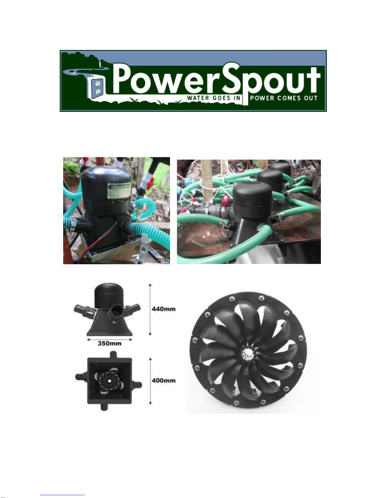
2.1.1. Turbine protective casing
The PowerSpout TRG is encased in a very
durable LDPE casing and fairing, ensuring all
internal parts are protected from rain, rodents,
children and UV etc. The turbine can be
installed outside as it is protected from sun and
rain by its fairing.
The generator temperature should always be
checked as part of the turbine commissioning
by the installer, particularly when high power
turbines are installed in very hot climates.
The fairing on your PowerSpout turbine
forms part of an electrical enclosure. In
many cases there will be lethal voltages
present during operation.
2.1.2. Valves
Four valves are supplied with your TRG turbine.
Thread is female 2" BSP (or NPT can be supplied by order). More
about thread sizes.
Used as on/off control of flow to jets.
Can be mounted directly on TRG jet-holders, but when used with
camlocks and hoses we recommend fitting the valves at the supply
pipe end of the hoses instead.
Grease the threads well.
PowerSpout TRG installation 2018
Last revised July 2018 © 2018 EcoInnovation Ltd (NZ) Page 13
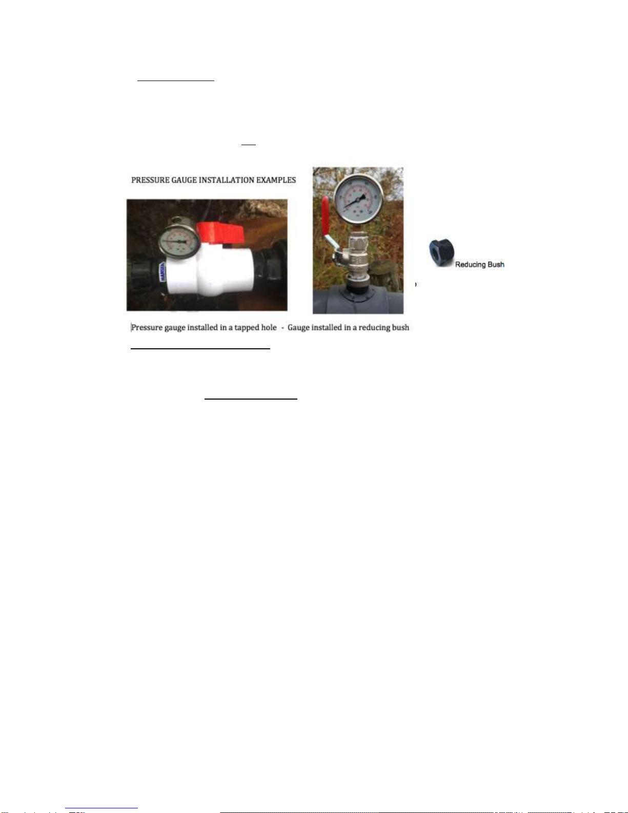
2.1.3. Pressure Gauge
Supplied with turbine.
Thread is 1/4" BSP male.
To be mounted on penstock or the manifold pipework upstream of the valves.
Normally this is done with a saddle, reducing bushes, (and optionally a valve), as shown
below right. (These fittings are not supplied).
Can also be mounted in a hole (drilled and tapped) in pipe or fittings.
Convert the units of pressure:
9.8kPa = 1 metre of head
43 PSI = 100 feet of head
The pressure gauge is absolutely essential for commissioning, troubleshooting and flow
management, so you must install it.
The gauge is slightly affected by temperature changes, so for maximum accuracy you
should vent it by pushing the rubber bung aside with a thumbnail. This allows air to enter or
leave the casing. Or snip off the nipple on the top of the plug, if plug is uppermost.
Measure the static pressure (valves closed) and compare this with the design calculation. If
it is low then check for air trapped in the supply pipeline (called penstock). If it is high then be
ready for more power than expected (for a given size jet). Your circuits and equipment need
to be fit to carry this extra load or you need to use smaller jets.
Measure the dynamic pressure (valves open) and compare this with static pressure to
calculate the pipe efficiency percentage. Does this match the calculation?
If turbine output is low then the pressure gauge helps you find the cause.
Low pressure could mean blocked filter, lack of water flow, or trapped air in the pipe.
Higher than usual running pressure could mean an obstructed jet.
PowerSpout TRG installation 2018
Last revised July 2018 © 2018 EcoInnovation Ltd (NZ) Page 14
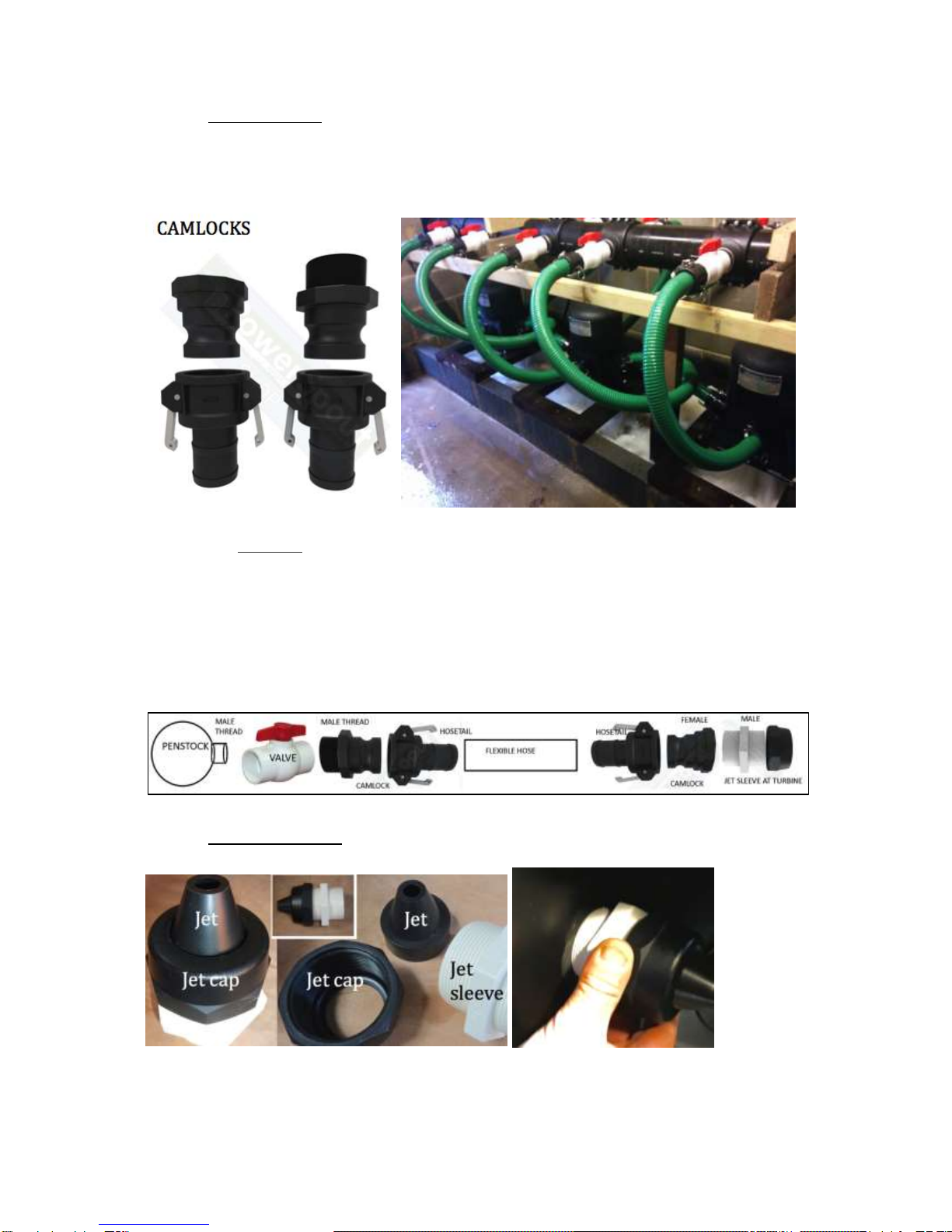
2.1.4. Camlock fittings
These quick-release fittings are ideal for connecting flexible 50mm (2”) ID hoses to your turbine.
Grease the threads liberally. Soften the hose in boiling water, push or hammer the hosetail
in, and secure with clamps. Ensure that there is no stress in the pipe where the camlock fittings
lock together.
Do not forget to fit the pipe supports. There are none in the photo above. The valve is best
placed at the upstream end so that you can detach your turbine from the pipework for servicing.
Our camlock fittings are rated for up to 6 bar (87 PSI or 60m head) and include 1 male and 1
female thread. Be aware that at flows exceeding 3 litres/second per jet you will suffer some loss
of head in these small-bore fittings. This may mean that the turbine output is less than predicted.
The diagram below shows the sequence of connections between the penstock (supply pipe) and
turbine. You can use one of our pipe saddles to provide a male thread on the penstock and
mount the valve on that, followed by the camlock-hose-camlock sequence, leading to the jet
sleeve on the turbine.
2.1.5. Jet sleeve and cap
Supplied with turbine.
Grease threads liberally. Tighten the camlock onto jet sleeve outer end with a wrench.

PowerSpout TRG installation 2018
Last revised July 2018 © 2018 EcoInnovation Ltd (NZ) Page 15
Jet cap should only be hand-tightened, to retain jet insert on the inner end of the jet sleeve.
But take care it does not fall off and get washed away.
2.1.6. Jet inserts
The jets control the flow rate. A larger orifice results in more flow. Use a suitable size and
number of jets to harvest most of the available flow at any given time. If the available flow is
sometimes insufficient to feed your chosen jets, then air will enter the penstock, reducing the
efficiency of the turbine. Then you must use fewer and/or smaller jets to get the most power
from your diminished flow.
You will be supplied with jets that will deliver the correct flow for your site as you have
reported it.
Four spare jet inserts are also supplied with your turbine. The hole inside is tapered.
Enlarge the jet by shortening the plastic insert on site with a sharp knife. The inserts are
inexpensive so a trial and error approach can quickly determine the correct jet size.
It is important to cut your jet to the correct size cleanly so that the water jet can break
smoothly without spray. We recommend using a sharp knife and paring away at the jet,
cutting from the inside edge out. With practice a very accurate and sharp edged jet can be
prepared in the field. The taper gauge and knife supplied in the optional PLT tool kit helps to
make this task easy.
Holding the plastic jet within a spare holder sleeve and end cap will ensure
the jet is held firmly while you cut it to size. Take care, as it is easy to slip,
which could result in a significant flesh wound. If you have Kevlar gloves,
wear them.

PowerSpout TRG installation 2018
Last revised July 2018 © 2018 EcoInnovation Ltd (NZ) Page 16
Jet alignment
You can optimise the angle of the
jet during commissioning by trial
and error movements of the
incoming pipe angle.
Always support this pipe at the
optimum angle as part of the
commissioning process.
During manufacture, a jig is used
to obtain good jet alignment. The
jig is a 1mm wire that is held
centrally in the jet holder but can
be moved in and out. Alignment
is done by heat setting the case
material around each jet holder.
Problems arise when the jets are not supported prior to filling with water, as this pipe weight
can distort the heat set we put in the casing. Armed with a heat gun this can be fixed if the
above has occurred and the force to correct on the jet support feels too high.
PowerSpout TRG installation 2018
Last revised July 2018 © 2018 EcoInnovation Ltd (NZ) Page 17
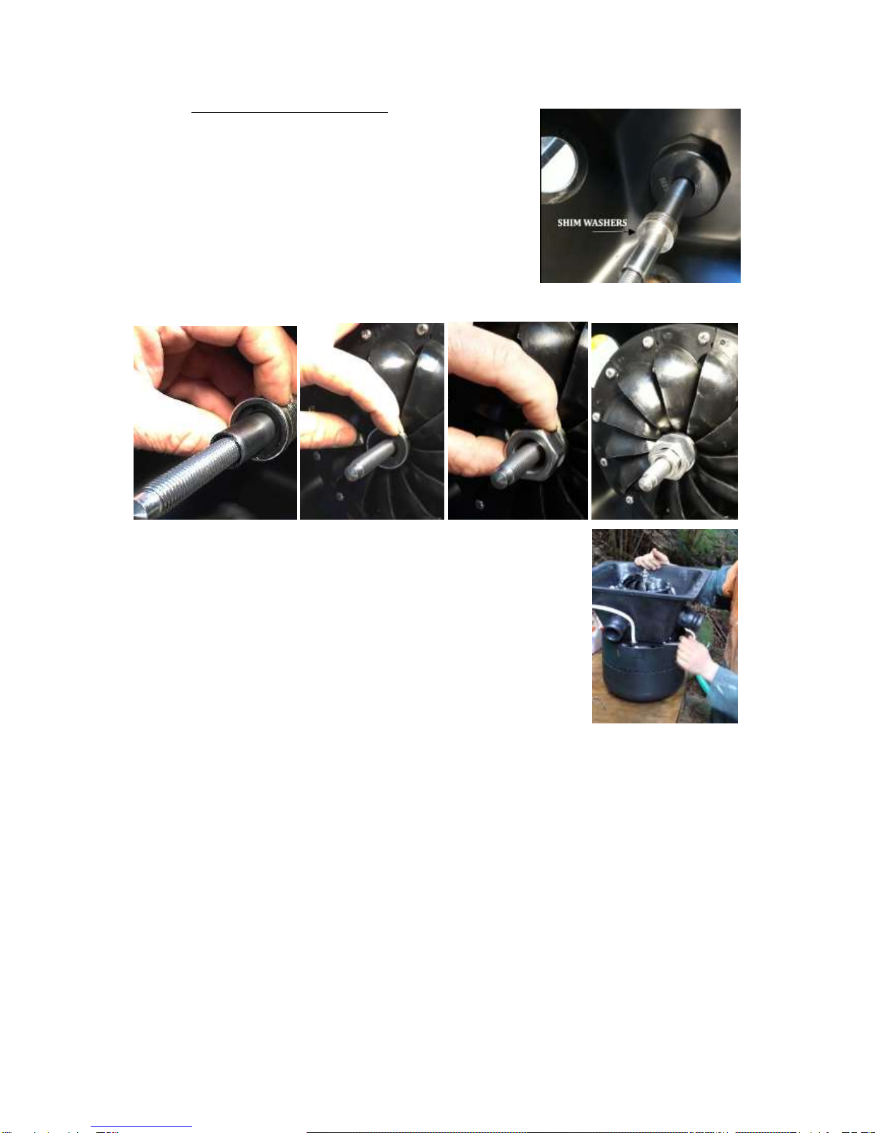
2.1.7. Turbine runner/rotor mounting
The wet side rotor, or "runner" is fitted to the bottom "wet
end" of the shaft. Take care that the runner is the right way
around to spin clockwise as shown below.
Fit the shim washers first. The height of the runner is
factory set using the correct number of shim washers. If you
remove the runner then take care to keep these washers
and refit them exactly as supplied.
The turgo runner itself is clamped to the shaft using two
"taper caps" behind and in front. The large nut slips loosely over the shaft, and the smaller
nut thereby applies pressure to the taper cup clamping arrangement.
Tighten the nut to 50 Nm torque or "very tight". The runner may be
damaged if it slips.
(50Nm/37ftlb is the same as 25kg weight at the end of a 20cm long
spanner or wrench.)
PowerSpout TRG installation 2018
Last revised July 2018 © 2018 EcoInnovation Ltd (NZ) Page 18
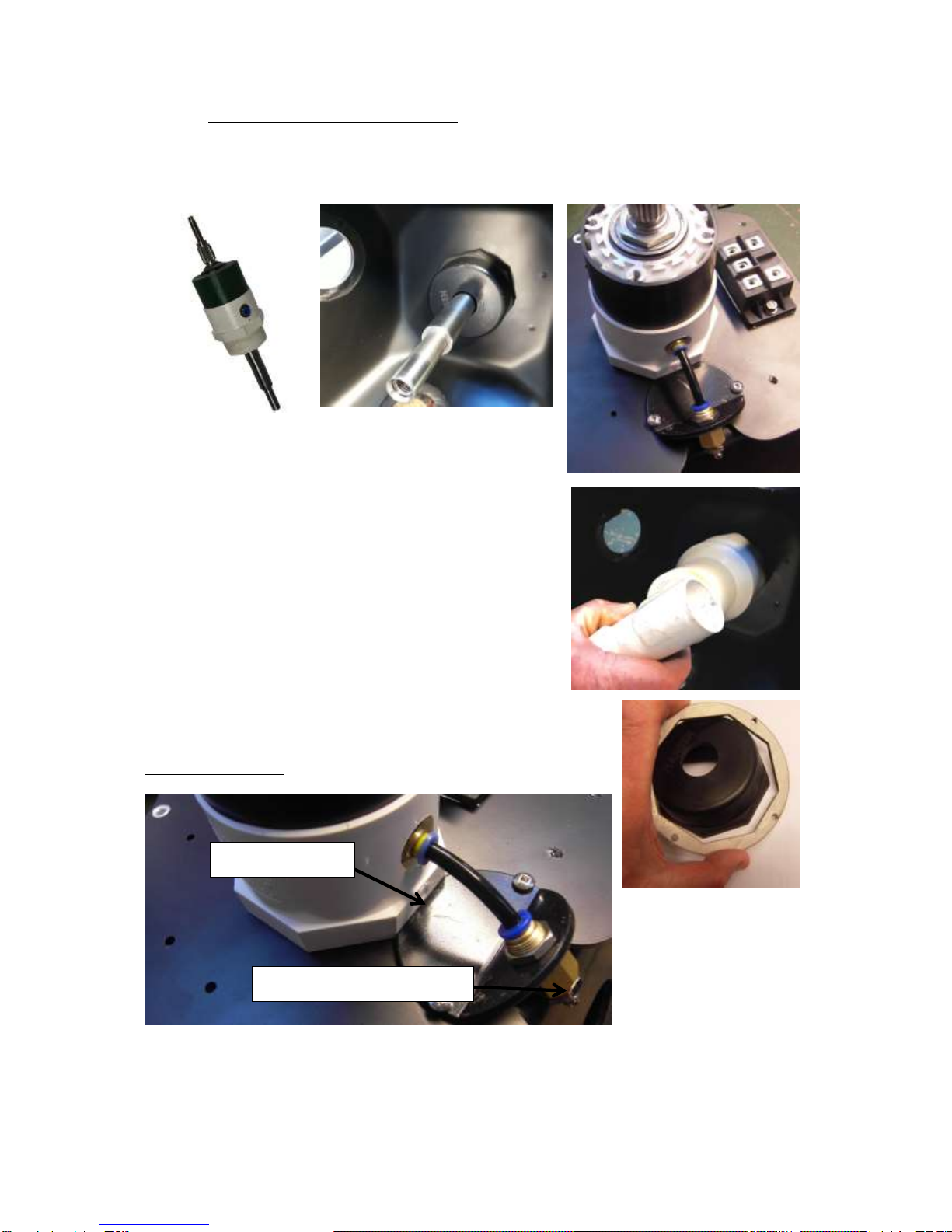
2.1.8. Shaft and bearing block installation
You need to remove and refit the shaft and bearing block assembly in order to change the
bearings. It's a good idea to order a spare shaft and bearing block with your turbine. That
way you can be back in operation at once and change the bearings later.
Fit the bearing block through the baseplate and casing.
Retain it in place with the threaded black plastic cap nut.
This cap has hexagonal part 91mm across the flats. Be
sure to tighten it very securely so the turbine does not
come loose.
You can make a box spanner/wrench using a PVC 90-63
OD pipe connector PVC pipe fitting (as shown right) heat-
formed into shape.
We also sell laser cut socket ends (below right). Clients
screw this to a short length of 100mm PVC pipe. Or we
can supply the tool complete.
You may alternatively be able to simply hold the cap in
place whilst tightening the block itself down onto the plate very
firmly with a large set of channel locks or pump pliers.
Fit the locking plate to prevent rotation and loosening.
Locking plate
Manual grease nipple

PowerSpout TRG installation 2018
Last revised July 2018 © 2018 EcoInnovation Ltd (NZ) Page 19
2.1.9. Changing the bearings
Bearings should be checked at each service and replaced as required when slack or noisy.
If bearings are used for more than one year without purchasing and fitting three of our
automatic grease canisters then there is no warranty cover for any damage resulting from
bearing failure. However bearings can last more than one year with care at your discretion.
Refer to Bearing care guide for more information.
Bearings specifications:
Front and rear 6005-2Z OD 47mm ID 25mm. Select premium quality bearings.
Steel shields (denoted by letter 'Z') are preferable to rubber seals (that have higher friction).
Removing old bearings
Slacken the retaining nut by holding it in a vice whilst turning the shaft's wet end with a pair
of grips. Use the jaws of the vice (not tightened) as a support for the block. Then strike the
end of the shaft to drive it out of the block. Take care not to damage the shaft. Knock the
shaft out of the wet end bearing in the same fashion. Youtube link.
These images show a PLT bearing block but the principle is the same for a TRG.
Use a suitably long bolt as a drift to hammer the remaining bearing out of the block.
Tap the new ones in taking care to strike only the outer race and not damage the shield.
A large socket (if available) can be used as a drift for the recessed bearing.
Clean the housings and the shaft to remove traces of retaining compound and any grease.
Apply fresh retaining compound Loctite 680 sparingly as shown below (also to the thread).
Drive the shaft fully into place with a hide mallet (or put a block of plastic over the wet end to
protect it from your hammer).
Finally tighten the locknut on the dry end, using the same technique as used to remove it.
Do not over-tighten. You want the bearings to spin freely
PowerSpout TRG installation 2018
Last revised July 2018 © 2018 EcoInnovation Ltd (NZ) Page 20
2.1.10. Greasing the bearings
For a longer document on this subject please see our Bearing care guide.
If you are reading this for the first time following a
bearing failure you are too late and some damage
(other than bearings) is likely to have occurred.
The photo (right) shows typical shaft damage due to a
worn-out bearing. When the bearing does not spin
freely, it spins on the shaft instead, which rapidly wears
it down until it is unfit for future use.
Grease type
Any grease is better than no grease. You must
grease the bearings.
Quality is less important where canisters ensure a steady flow.
If possible, use waterproof grease.
Where the turbine power output is low you will benefit greatly from using a low-
viscosity grease.
We recommend SKF LESA 2 grease for all PowerSpout applications or a close
equivalent.
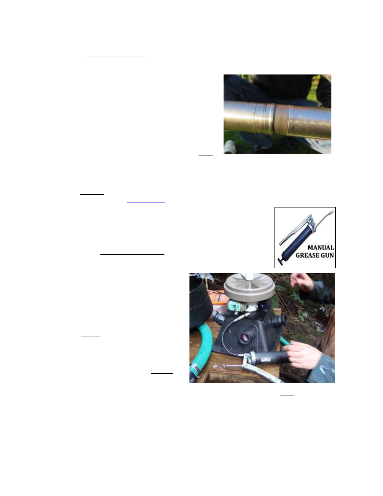
Manually applied lubrication
Sealed bearings do need to be re-greased at times, because hydro
turbines run 24/7 and see very high cycle rates. The PowerSpout is
provided with a re-greasing nipple (Zerk fitting) so this can be easily
done. Do this with the shaft spinning (driven either by water power or
using a cordless drill with a 19mm socket attachment).
Pump into the bearing block about 40 ml of
grease when first commissioning. This is
normally about 40-60 pumps of a domestic
type grease gun. Grease the bearings with
the magnetic rotor removed. Once you see
grease on the dust shield you can stop.
Smear this expelled grease onto the shaft
spline. (Perform any checks of output
voltage before doing this as the fresh
grease will affect the maximum off-load
speed.)
Subsequent re-greasing should be about 5
ml of grease (about 5-8 pumps) with the
shaft spinning.
You should lubricate your PowerSpout bearings when you first use it (directly after any
measurements of open circuit voltage) and then (at least):
Every 12 months for generation up to 300 W.
Every 6 months for generation up to 600 W.
Every 3 months for generation up to 1600 W.
This manual suits for next models
5
Table of contents
Popular Portable Generator manuals by other brands


Mosa
Mosa S Series Use and maintenance manual

Generac Mobile
Generac Mobile MLG15 owner's manual

Airworks Compressors
Airworks Compressors TWISTER T40 Installation & operation manual

Teknoware
Teknoware TKT66 Installation and maintenance instructions

Velleman
Velleman VM120 manual

Kohler
Kohler 48RCLB Operation