ECOLINE TV7094 User manual

Day/Night Speed dome camera /
LCD-keyboard
INSTALLATION INSTRUCTIONS
TV7094
TV7091
1

Preface
Dear customer,
thank you for purchasing this ECOLINE digital surveillance camera. You made the right
decision in choosing this state-of-the-art technology.
This product complies with the current standards of domestic and European regulations. The
CE has been proven and all related certifications are available from the manufacturer upon
request.
To maintain this status and to guarantee safe operation, it is your obligation to observe these
operating instructions!
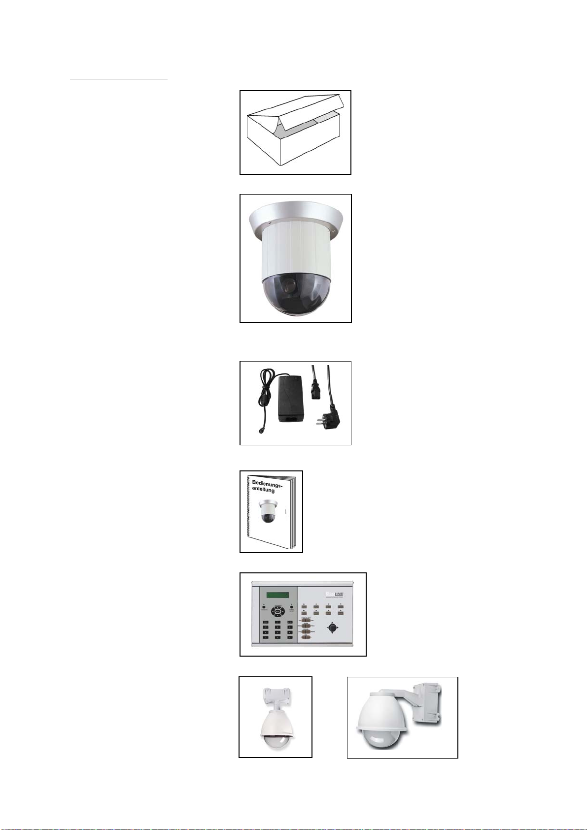
This ECOLINE speed dome camera is used in combination with video sources (cameras) and
recording devices (VHS or digital recorders) for the purpose of property surveillance. It
enables the user to build up a flexible and wide ranging surveillance. Enclosed in a
weatherproofed housing it is the ideal outdoor protection. Furthermore the ECOLINE speed
dome camera offers 6 alarm inputs which interact with the camera position. Through its
adjustable rotation speed, 360° endless rotation, 180° tilt angle and 128 preset position, the
camera offers an easy setup and a comfortable usage.
Precautions
It must be ensured that the ECOLINE speed dome camera and connected components are
kept free of moisture (cellars and similar surroundings are to be strictly avoided). Use of this
product for other than the described purpose may lead to damage of the product. Non-
compliant use may also be hazardous (e.g. short circuit, fire, electrical shock). The power unit
is suitable for operation on the public power network with 230 Volt / 50 Hz (1.5A) alternating
current.
No part of the product may be changed or modified in any way. Connection to the public
power network is subject to country-specific regulations. Please be aware of applicable
regulations in advance.
To avoid fire and injury,
please observe the following:
•Securely fasten the device
at a dry location in the
building.
•Ensure sufficient air
circulation.
•Do not expose the device
to temperatures less than -
10°C or more than 50°C.
•The device is designed for
indoor use only or for
outdoor use with the
suiteable outdoor housing.
•Humidity must not exceed
90% (non-condensed).
•Ensure that the voltage is
disconnected when
performing work on the
device. Please observe the following
regulations to ensure
trouble-free operation of
your device:
•The ECOLINE speed dome
camera is supplied with
12VDC power by an
external transformer.
•The transformer should be
connected to the 230VAC
building mains by means of
a separate, electrically
protected line.
•Connection work to the
building mains is subject to
country-specific regulations.
2

Improper or careless
installation work may lead to
faults and poor image
quality. Therefore please read
the instructions very carefully
and follow the installation
instructions for lines and
components precisely.
General:
3

Content
SCOPE OF DELIVERY..................................................................................................................................5
IN CASE OF OUTDOOR INSTALLATION OF THE SPEED DOME, USE AN OUTDOOR HOUSING. ........5
OVERVIEW ..................................................................................................................................................7
SYMBOL DESCRIPTION ..............................................................................................................................7
COMPONENT AND STRUCTURE DESCRIPTION .......................................................................................8
CAMERA SETTING ......................................................................................................................................9
TERMINAL FOOT CONNECTION, DATA LINE AND SIGNAL LINE REGULATION ................................ 11
INSTALLATION OF THE SPEED DOME CAMERA.................................................................................... 12
BACK PANEL TERMINALS........................................................................................................................ 14
OPERATION.............................................................................................................................................. 15
KEYBOARD BUTTONS .............................................................................................................................. 17
SET PRESET...................................................................................................................................... 17
GO PRESET..................................................................................................................................... 18
AUTO PAN...................................................................................................................................... 18
AUTO FOCUS................................................................................................................................. 19
FOCUS CONTROL ......................................................................................................................... 19
IRIS CONTROL................................................................................................................................ 19
ALARM MANAGEMENT.......................................................................................................................... 21
ALARM INPUT................................................................................................................................. 21
ALARM OUTPUT ............................................................................................................................. 21
STOP ALARM CONDITION............................................................................................................ 21
OSD OPERATIONAL DESCRIPTION........................................................................................................ 22
SIMPLE OPERATIONAL REFERENCE TABLE............................................................................................ 25
CONNECTING PELCO-KEYBOARD (KBD200A/KBD300A) .................................................................. 26
TROUBLE SHOOTING............................................................................................................................... 29
TECHNICAL DATA ................................................................................................................................... 30
4

Scope of delivery
Packaging
ECOLINE speed dome camera
Power unit with connection cable
Installation guides
In order to control the speed dome
camera, use the keyboard (TV7091)
In case of outdoor installation
of the speed dome, use an
outdoor housing.
5

(TV7092) (TV7093)
6

Overview
•Speedy response with 26 times continuous auto-focus zoom lens and 10 times
Electronic Zoom
•Auto Iris and Manual Iris Control
•Advanced DSP Camera, including Auto White Balance, Backlight Compensation and
Auto Iris Control.
•360° Continuous Pan Rotation.
•128 Preset Points Setup.
•Continuous Auto Focus
•Variable Speed 1°~300°/Sec
•Horizontal Rotation of 180°.
•Built in 6 Alarm Inputs and one Relay Output
•Two types of Alarm out signal are provided: NO and NC.
•Remote Control via RS-485
•Connects up to 127 Speed Dome Cameras.
•Supports PELCO protocol (D and P protocol)
•PC Control is applicable after transformation using the Communication Interface has
been completed.
•12VDC Power Input (AC100~
240V, 50Hz or 60Hz)
•Suitable for installation on different occasions; can be installed outside (with outdoor
dome housing), flush mount on a ceiling or in the ceiling with only the dome showing.
•UVV certified
Symbol description
Function keys are shown by, framed capital boldface print letters.
Example: ENTER ,AUTO FOCUS , etc.
Function key “+” indicates the order sequence.
Example: 2 8 + ENTER meaning, press the function key “ 2 “, ” 8 ”, and then ENTER .
; indicate messages from the device and is shown on the control
keyboard
⎥
⎦
⎤
⎢
⎣
⎡_:001DEVICE
LCD display.
“n” indicates the ID number of the nth device (ID numbers ranges from 001~127).
7

Component and structure description
(5)
(4)
(3)
(
2
)
(1)
(1) Elektronic Alarm input or output / Video input / Power input terminal
(2) Elektronic ID position setup
(3) Elektronic Embellish Cover
(4) Mechanic Machine housing
(5) Camera
module
Transparent cover / Black housing
8

Camera setting
DIP-Schalter
SW1
Connection of up to 127 Speed Dome
Cameras, each camera has its own ID
number.
Please setup each camera with its own
ID number. Else the system is not able to
differentiate between the different
camera modules. Start with ID number
001.
SW1: ID number setting
Setting an ID to 000 will lead the display
to print
DEVICE N/A .
DIP switch setting according to ID number:
9

SW2: Protocol setup
Setup
DIP switch number
#4 #3 #2 #1
Applied protocol
Off Off Off Off YOKO
Off Off Off On PELCO
Off Off On Off Reserviert
Off Off On On Reserviert
* Speed dome automatically detects the type of PELCO Protocol. No switch settings are
required to set D and P Protocols.
SW3: Baud rate settings
Setup
DIP switch number
#4 #3 #2 #1
Baud-Rate
Off Off Off Off 9600 BPS
Off Off Off On 4800 BPS (P)
Off Off On Off 2400 BPS (D)
Off Off On On 19200 BPS
* Setup for YOKO-protocol: SW2: Off Off Off Off, SW3: Off Off Off Off
10

Terminal foot connection, data line and signal line regulation
RJ-11
Input/Output
6
~
1 6
~
1
RS-485
Input/Output
5
~
1
12VDC
power
Alarm input/output
10 ~1
Video output
(1) Power 12VDC Connect the plug of a 12VDC,1.5A power source.
(2) Video output Video signal output of VCBS 1.0Vp-p 75Ohms BNC.
The speed dome camera is equipped with 6 external alarm
triggering inputs and 2 sets of alarm outputs (1 set NO and 1 set
NC). Refer to the pinouts:
PIN 1 Alarm input 1 PIN 2 Alarm input 2
PIN 3 Alarm input 3 PIN 4 Alarm input 4
PIN 5 Alarm input 5 PIN 6 Alarm input 6
PIN 7 Ground PIN 8 Common
(3)
Alarm input/
output
PIN 9 Alarm output NC PIN 10 Alarm output NO
Connect the communication control input and output terminal as
follows:
PIN 1 Input data + PIN 2 Input data -
PIN 3 Ground PIN 4 Output data +
(4)
RS-485 input /
output
PIN 5 Output data -
Alternatively connect the RJ-11 communication control input and
output as follows:
PIN 1 Not used PIN 2 Not used
PIN 3 Ground PIN 4 Data +
(5) RJ-11 input/
output
PIN 5 Data - PIN 6 Not used
11

Installation of the speed dome camera
In ceiling mount Flush mount
12

Description of the keyboard
(9)
(8) (10) (11) (12)
(6) (7)
(1) System reset Press this button to reset and restart the system.
(2) Key buttons These buttons are used to select certain speed dome cameras and
preset positions.
(3) Lens buttons These buttons are used to manually adjust the lens.
(4) ID-select This button is used to select a certain speed dome camera.
(5) Joystick To control the selected camera manually.
(6) LCD display To display important messages.
(7) OSD menu Push this button to open up the OSD of the speed dome camera.
(8) OSD / LCD keys Use these buttons to navigate through the OSD of the keyboard
and the camera.
(9) Preset buttons These buttons are used to setup and select preset positions.
(10) Auto button These buttons activate the auto mode for panning and focus.
(11) Speed control Push this button to adjust the speed dome cameras pan and tilt
speed according to the zoom factor.
(12) Relais buttos These buttons are used to maually activate up to three relais.
(5)
(4)
(3)
(2)
(1)
13

Back panel terminals
(1
)
(3
)
(2
)
(1) Power 12VDC Connect a 12VDC, 1,5A power source.
(2) RS-485 terminal To connect the 2 wires communication control cable to the speed
dome
D+D- D+D-
(3) RJ-485 / RJ-11 Alternatively you can connect the dome via the RJ-11 connector.
System installation
14
Keyboard Monitor
The system supports connections of
numerous Speed Dome Cameras or
P/T/Z Receivers, assigning a set ID
(Note! ID numbers ranges from
1~127 and may not be repeated)
for setup and control, through
control keyboard
Connecting RS-485
Connect RS-485 terminal D+ from
the control keyboard to terminal D+
of RS-485 DATA IN connector from
the device; then connect RS-485
terminal D- (the same set of
terminal) to the terminal D- of RS-485
DATA IN connector from the device.

Operation
System reset and first usage
After connecting all necessary cables startup the system linking by following this proceedure.
The same proceedure is nedded to reset the system:
1.Step: Press the button SYS RESET .
The LCD displays the following message:
⎥
⎦
⎤
⎢
⎣
⎡LINKING?SYSTEM
The LED starts flashing.
2. Step: Press the button SYS RESET again.
The system linking will start, search the system connection device and make sure that
all the
connected devices are probably linked.
When the display shows the following message it means
that an
error has been occurred. In this case refer to step 3, else the camera is ready for the
setup.
⎥
⎦
⎤
⎢
⎣
⎡
RESETSYSPRESS
LOSTXXX:DEVICE
3. Step: Check the cabeling of the communication cable from the keyboard to the
connected speed dome
cameras. After the power up proceedure of the speed dome, it check the pan and
tilt functionality.
Having checked and sorted the circuit and the speed domes power condition, press
the
button
SYS RESET again.
Manual control of the speed dome
1. Step: First choose the camera that you want to control. Therefore key in the ID of the
speed dome as a
three digit number, e.g. 001for the speed dome with the ID 1.
2. Step: Confirm your ID number by pressing the ENTER button.
The keyboard’s LCD displays:
⎥
⎦
⎤
⎢
⎣
⎡_:001DEVICE
3. Step: Use the joystick to manually control the spees dome (up, down, left, right, speed)
NOTE: To be able to set up the speed dome’s postition precisely also at a high zoom ratio,
press the SPEED BY ZOOM button. The function is activated if the button’s LED is lid. The
function slows down the speed dome’s speed according to the zoom ratio. The higher the
ratio, the slower the dome will move. The function only works for manual control, not when
changing preset positions.
4. Step: Use the buttons ZOOM TELE and ZOOM WIDE, to set the zoom ratio
accordingly.
15

The button
ZOOM TELE is used to zoom in. Objects are displayed bigger. The
angle of viewing becomes more and more narrow.
The button
ZOOM WIDE is used to zoom out. Objects are displayed smaller. The
angle of viewing becomes wider.
16

Keyboard buttons
SET PRESET
The SET PRESET is used to setup individual selected pregrogrammed positions, so called
preset positions. To store a current position as preset position follow steps given below:
1. Step: Choose a speed dome camera in which you want to programm a preset position,
e.g. camera 1:
Key in: 001ENTER
The keyboards LCD displays: ⎢
⎥
⎦
⎤
⎣
⎡_:001DEVICE
2. Step: Use the joystick to move the camera to the desired position. Use the zoom and focus
buttons to individually setup the picture.
NOTE: It is not recommended to use the auto focus function in combination with preset
positions as the camera needs time to focus on the object. It is recommended to set the
focus with the preset position. Simply select and store the focus manually.
3. Step: Key in the number. This number will be stored with the selected preset position. To
store the number, e.g. number 1 and the selected position for this dome press the button
SET PRESET .
Please enter: 001SET PRESET
The keyboard’s LCD displays:
⎥
⎦
⎤
⎢
⎣
⎡
?XXX
PRESETTOSAVE
4. Step: Press SET PRESET again.
The keyboard’s LCD displays:
⎥
⎦
⎤
⎢
⎣
⎡OK!SAVE
NOTE: Each speed dome camera can store up to 128 preset positions. Repeat steps 1 to 4 to
store other positions. Preset positions cannot be individually erased. You have to select and
store a different position for the number to change the selection.
17

GO PRESET
The GO PRESET button is used to direct the speed dome camera to a prior stored preset
position. To call a preset position follow the steps given below:
1. Step: Choose a speed dome camera in which you want to programm a preset position,
e.g. camera 1:
Key in: 001ENTER
The keyboards LCD displays: ⎢
⎥
⎦
⎤
⎣
⎡_:001DEVICE
2. Step: Key in the desired preset position number, e.g. number 1
Key in: 001GO PRESET
The keyboards LCD displays: ⎢
⎥
⎦
⎤
⎣
⎡_:001DEVICE
The speed dome camera will automatically be directed to the selected position
NOTE: To change the current position you can either:
a) select a different preset position as explained above
b) select a different position using the joystick
AUTO PAN
The auto pan mode enables the user to group 32 prior programmed preset positions in up to
4 groups. Once activated the auto pan function, the dome recalls automatically the
preprogrammed preset positions. Use the OSD of the keyboard to arrange preset position into
auto pan groups.
NOTE: By factory default the speed dome offers 2 additional groups which settings cannot be
changed
group 5 – continuous panning within preset positions 1,2 and 3.
group 6 – continuous panning within preset positions 4,5 and 6.
To activate an auto pan group please proceed as follows:
1. Step: Choose a speed dome camera in which you want to programm an auto pan group,
e.g. camera 1:
Key in: 001ENTER
The keyboard’s LCD displays:
⎥
⎦
⎤
⎢
⎣
⎡_:001DEVICE
2. Step: Key in the desired auto pan group, e.g. number 1
18

Key in:
001AUTO PAN
The keyboard’s LCD displays:
⎥
⎦
⎤
⎢
⎣
⎡
1:GROUPAUTOPAN
:001DEVICE
The AUTO PAN LED is lid.
Stop the auto pan function
To stop the auto pan function simply press the button AUTO PAN again.
The LED is not lid.
NOTE: As long as the auto pan function is activated (LED is lid) it is not possible to control
the speed dome manually or choose a different function. Stop the auto pan funtion first.
AUTO FOCUS
The AUTO FOCUS button activated the auto focus function of the lens. Objects will be
automatically focusd when in range. The speed dome camera always focusses on the center
of the picture. Objects which are not in the center may not be focussed and displayed sharp
(especially at a high zoom ratio and a narrow viewing angle). If you want to adjust the focus
manually or to programm a preset position the auto focus function needs to be deactivated
by pressing the AUTO FOCUS button. (LED is not lid).
FOCUS CONTROL
The FOCUS CONTROL is a button that enables the user to manually set the focus and
sharpness of the picture.
NOTE: In cases where also the manual focus does not increase the sharpness of the picture
zoom out and widen the viewing angle. Try to focus again. If you have chosen a very narrow
viewing angle and a high zoom ratio the focus area is only about 0,5m to 1,5m.
IRIS CONTROL
The IRIS CONTROL is a button that enables the user to manually set the iris control.
NOTE: The function IRIS CONTROL is only available for the following modes: „auto exposure“,
„auto iris“ and „manual“.
NOTE: The smaller the iris opening, the bigger the focus area. It may happen that under day
light conditions (bright light, small iris opening) the whole picture is displayed sharp. During
night time use or under low light conditions (big iris opening) parts of the choosen picture
(especially in front of and behind the focus point) may not be displayed sharp.
CHANNEL SELECTION
19

The CH+/CH- button enables the user to select the next higher (+) or lower (-) speed dome
ID number.
20
This manual suits for next models
1
Table of contents
Other ECOLINE Security Camera manuals
Popular Security Camera manuals by other brands

Honeywell
Honeywell ACUIX Installation and configuration guide

Tyco
Tyco Illustra Standard E Series quick start guide

Watec
Watec WAT-902H2 Ultimate Operation manual

Samsung
Samsung SNV-6013 user manual

Atlantis
Atlantis A14-PC7000-HD1 quick start guide

Panasonic
Panasonic WVNM100 - NETWORK COLOR CAMERA operating instructions

American Dynamics
American Dynamics SpeedDome Optima LT Installation and service manual

ANPVIZ SECURITY
ANPVIZ SECURITY U-Easy Series user manual

ENFORCER
ENFORCER ENFORCER EV Series manual

ISSI
ISSI PSP-CCD-C user guide

ALIBI
ALIBI ALI-TS4002R Quick installation guide

Teledyne
Teledyne P4-CM-04K07D user manual